DATASHEET
ISL35411
FN6971
Rev 2.00
June 23, 2016
Quad Driver
The ISL35411 is a quad de-emphasis driver with extended
functionality for advanced protocols operating with line rates
up to 11.1Gbps. It integrates a high-speed driver/limiting
amplifier with built-in de-emphasis to compensate for the
frequency dependent attenuation of PCB traces and twin-axial
copper cables. Supported protocols include 4k/8k video
capable DisplayPort v1.3 (HBR1/2/3), InfiniBand (QDR), 40G
Ethernet (40GBASECR4/SR4) and 10G SFP+ specification
(SFF-8431).
Features
Used in conjunction with Intersil's ISL36411 receive-side
equalizer, the ISL35411 enables active copper cable
assemblies that support 10G serial data transmission over
>15m of twin-axial copper cables.
• Supports 64b/66b encoded data - long run lengths
Operating on a single 1.2V power supply, the ISL35411
enables per channel throughputs of 10Gbps to 11.1Gbps. High
data rates are achieved by using Current Mode Logic (CML)
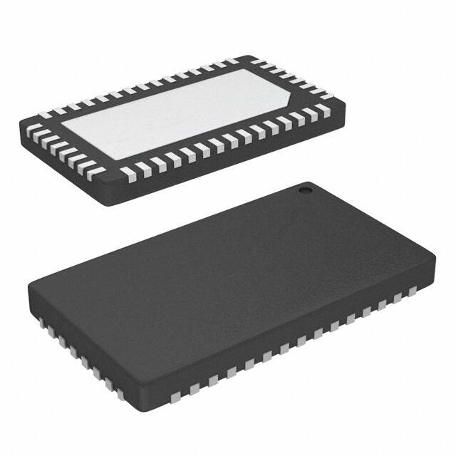
inputs and outputs and is packaged in a 4mmx7mm 46 Ld
QFN.
• TX_Disable
Related Literature
• InfiniBand (QDR)
• AN1572, “ISL36411 Evaluation Board User Guide”
• 40G Ethernet (40GBase-CR4/SR4)
• Supports four channels with data rates up to 11.1Gbps
• Low power (90mW per channel)
• Low latency
• Adjustable output de-emphasis
• Four drivers in a 4mmx7mm QFN package for straight route
through architecture and simplified routing
• Line silence preservation
• 1.2V supply voltage
Applications
• DisplayPort v1.3 active copper cable modules
• QSFP active copper cable modules
• 100G Ethernet (100GBase-CR10/SR10)
• High-speed printed circuit board (PCB) traces
Benefits
• Thinner gauge cable
• Extends cable reach greater than 3x
• Improved BER
ACTIVE COPPER CABLE ASSEMBLY
1.2V
Host Channel
Adapter
10nF
1.2V
100pF
VDD
10nF
IN1[P,N]
100pF
TDSBL
DE
8-PAIR DIFFERENTIAL 100˖
7:,1�$;,$/�&$%/(
VDD
0.1˩)
IN1[P,N]
OUT1[P,N]
IN2[P,N]
OUT2[P,N]
OUT1[P,N]
0.1˩)
IN2[P,N]
OUT2[P,N]
0.1˩)
0.1˩)
Rx1[P,N]
Rx2[P,N]
0.1˩)
Tx2[P,N]
ISL36411
0.1˩)
ISL35411
0.1˩)
IN3[P,N]
OUT3[P,N]
0.1˩)
IN4[P,N]
IN3[P,N]
OUT3[P,N]
IN4[P,N]
OUT4[P,N]
1.2V
100pF
Rx4[P,N]
DT
10nF
1.2V
DT
FABRIC SWITCH
ื��P���$:*
10nF
0.1˩)
Tx4[P,N]
OUT4[P,N]
100pF
0.1˩)
Tx3[P,N]
Rx3[P,N]
0.1˩)
CONNECTOR PADDLE CARD
CONNECTOR PADDLE CARD
FIGURE 1. TYPICAL APPLICATION CIRCUIT
FN6971 Rev 2.00
June 23, 2016
Page 1 of 12
HOST ASIC
HOST ASIC
Tx1[P,N]
CP LOSB
0.1˩)
�ISL35411
Ordering Information
PART NUMBER
(Notes 1, 2, 3)
PART MARKING
TEMP. RANGE
(°C)
TAPE AND REEL
(UNITS)
PACKAGE
(RoHS Compliant)
PKG.
DWG. #
ISL35411DRZ-TS
ISL35411DRZ
0 to +85
100 (Sample Reel)
46 Ld QFN
L46.4x7
ISL35411DRZ-T7
ISL35411DRZ
0 to +85
1k
46 Ld QFN
L46.4x7
ISL35411DRZ-EVALZ
Evaluation Board
NOTES:
1. Please refer to TB347 for details on reel specifications.
2. These Intersil Pb-free plastic packaged products employ special Pb-free material sets, molding compounds/die attach materials, and 100% matte
tin plate plus anneal (e3 termination finish, which is RoHS compliant and compatible with both SnPb and Pb-free soldering operations). Intersil Pbfree products are MSL classified at Pb-free peak reflow temperatures that meet or exceed the Pb-free requirements of IPC/JEDEC J STD-020.
3. For Moisture Sensitivity Level (MSL), please see device information page for ISL35411. For more information on MSL please see techbrief TB363.
TABLE 1. KEY DIFFERENCES BETWEEN FAMILY OF PARTS
PART
NUMBER
DATA
RATE
(Gb/s)
MAXIMUM
CABLE
LENGTH DIFFERENTIAL
POWER
DEO/P SWING
NUMBER OF CONSUMPTION (24AWG)
EMPHASIS EQUALIZATION
(mVP-P)
(m)
(mW)
Tx OR Rx
(dB)
(dB)
DIFFERENCES
BETWEEN QLX
PARTS
TARGET
MARKET
ISL36411
11
4x Rx
440
20
650
N/A
30
N/A
DP1.3, 40GbE,
QSFP+
ISL35411
11
4x Tx
340
20
600
4
N/A
N/A
DP1.3, 40GbE,
QSFP+
QLX4600-SL30
6.25
4x Rx
312
30
600
N/A
30
4 pins for Loss of DP1.2, SAS-6Gb,
Signal (LOS) PCIe 2.0
QLX4600-S30
6.25
4x Rx
312
30
600
N/A
30
DP1.2, SAS-6Gb,
4 pins for
PCIe 2.0
Impedance
Selection
(= Power Down)
FN6971 Rev 2.00
June 23, 2016
Page 2 of 12
�ISL35411
Pin Configuration
VDD
GND
NC
DE1A
DE1B
DT1
NC
GND
ISL35411
(46 LD QFN)
TOP VIEW
46 45 44 43 42 41 40 39
VDD 1
38 OUT1[P]
IN1[P] 2
37 OUT1[N]
IN1[N] 3
36 VDD
TDSBL1 4
35 VDD
VDD 5
34 OUT2[P]
IN2[P] 6
33 OUT2[N]
IN2[N] 7
32 VDD
EXPOSED PAD
(GND)
TDSBL2 8
VDD 9
31 VDD
30 OUT3[P]
IN3[P] 10
29 OUT3[N]
IN3[N] 11
28 VDD
TDSBL3 12
27 VDD
VDD 13
26 OUT4[P]
IN4[P] 14
25 OUT4[N]
IN4[N] 15
24 VDD
GND
NC
NC
DE2B
DE2A
DT2
GND
TDSBL4
16 17 18 19 20 21 22 23
Pin Descriptions
PIN NAME
PIN NUMBER
VDD
1, 5, 9, 13, 24, 27,
28, 31, 32, 35, 36,
39
IN1[P, N]
2, 3
TDSBL1
4
IN2[P, N]
6, 7
TDSBL2
8
IN3[P, N]
10, 11
TDSBL3
12
IN4[P, N]
14, 15
TDSBL4
16
GND
17, 23, 40, 46
FN6971 Rev 2.00
June 23, 2016
DESCRIPTION
Power supply. 1.2V supply voltage. The use of parallel 100pF and 10nF decoupling capacitors to ground is
recommended for each of these pins for broad high frequency noise suppression.
Driver 1 differential input, CML. The use of 100nF low ESL/ESR MLCC capacitor with at least 6GHz frequency
response is recommended.
Transmit disable pin for Driver 1. Disables the driver when pulled to VDD. Connected to ground for normal
operation.
Driver 2 differential input, CML. The use of 100nF low ESL/ESR MLCC capacitor with at least 6GHz frequency
response is recommended.
Transmit disable pin for Driver 2. Disables the driver when pulled to VDD. Connected to ground for normal
operation.
Driver 3 differential input, CML. The use of 100nF low ESL/ESR MLCC capacitor with at least 6GHz frequency
response is recommended.
Transmit disable pin for Driver 3. Disables the driver when pulled to VDD. Connected to ground for normal
operation.
Driver 4 differential input, CML. The use of 100nF low ESL/ESR MLCC capacitor with at least 6GHz frequency
response is recommended.
Transmit disable pin for Driver 4. Disables the driver when pulled to VDD. Connected to ground for normal
operation.
These pins should be grounded.
Page 3 of 12
�ISL35411
Pin Descriptions (Continued)
PIN NAME
PIN NUMBER
DESCRIPTION
DT2
18
Detection Threshold for drivers 3 and 4. Reference DC voltage threshold for input signal power detection. Data
outputs OUT3 and OUT4 are muted when the power of IN3 and IN4, respectively, fall below the threshold. Tie
to ground to disable electrical idle preservation and always enable the limiting amplifier.
DE2[A, B]
19, 20
Control pins for setting de-emphasis on drivers 3 and 4. CMOS logic inputs. Pins are read as a 2-digit number
to set the de-emphasis level. A is the MSB and B is the LSB. Pins are internally pulled up and pulled down with
25kΩ resistors.
NC
21, 22, 41, 45
OUT4[N, P]
25, 26
Driver 4 differential output, CML. The use of 100nF low ESL/ESR MLCC capacitor with at least 6GHz frequency
response is recommended.
OUT3[N, P]
29, 30
Driver 3 differential output, CML. The use of 100nF low ESL/ESR MLCC capacitor with at least 6GHz frequency
response is recommended.
OUT2[N, P]
33, 34
Driver 2 differential output, CML. The use of 100nF low ESL/ESR MLCC capacitor with at least 6GHz frequency
response is recommended.
OUT1[N, P]
37, 38
Driver 1 differential output, CML. The use of 100nF low ESL/ESR MLCC capacitor with at least 6GHz frequency
response is recommended.
DE1[B, A]
42, 43
Control pins for setting de-emphasis on drivers 1 and 2. CMOS logic inputs. Pins are read as a 2-digit number
to set the de-emphasis level. A is the MSB and B is the LSB. Pins are internally pulled up and pulled down with
25kΩ resistors.
DT1
44
Detection Threshold for drivers 1 and 2. Reference DC voltage threshold for input signal power detection. Data
outputs OUT1 and OUT2 are muted when the power of IN1 and IN2, respectively, fall below the threshold. Tie
to ground to disable electrical idle preservation and always enable the limiting amplifier.
Exposed Pad
-
Exposed ground pad. For proper electrical and thermal performance, this pad should be connected to the PCB
ground plane.
FN6971 Rev 2.00
June 23, 2016
Not connected: Do not make any connections to these pins.
Page 4 of 12
�ISL35411
Absolute Maximum Ratings
Thermal Information
Supply Voltage (VDD to GND). . . . . . . . . . . . . . . . . . . . . . . . . . . -0.3V to 1.5V
Voltage at All Input Pins. . . . . . . . . . . . . . . . . . . . . . . . . . . . . . . -0.3V to 1.5V
ESD Ratings
Human Body Model
High-Speed Pins . . . . . . . . . . . . . . . . . . . . . . . . . . . . . . . . . . . . . . . .1.5kV
All Other Pins . . . . . . . . . . . . . . . . . . . . . . . . . . . . . . . . . . . . . . . . . . . 2kV
Thermal Resistance (Typical)
JA (°C/W) JC (°C/W)
46 Ld QFN Package (Notes 4, 5) . . . . . . . .
33
2.8
Operating Ambient Temperature Range . . . . . . . . . . . . . . . . 0°C to +85°C
Storage Ambient Temperature Range . . . . . . . . . . . . . . . .-55°C to +150°C
Maximum Junction Temperature . . . . . . . . . . . . . . . . . . . . . . . . . . . .+125°C
Pb-Free Reflow Profile . . . . . . . . . . . . . . . . . . . . . . . . . . . . . . . . . . see TB493
CAUTION: Do not operate at or near the maximum ratings listed for extended periods of time. Exposure to such conditions may adversely impact product
reliability and result in failures not covered by warranty.
NOTES:
4. JA measured in free air with the component mounted on a high effective thermal conductivity test board with “direct attach” features. See Tech Brief
TB379.
5. For JC, the “case temp” location is the center of the exposed metal pad on the package underside.
Operating Conditions
PARAMETER
Supply Voltage
Operating Ambient Temperature
MIN
(Note 6)
TYP
MAX
(Note 6)
UNIT
VDD
1.1
1.2
1.3
V
TA
0
25
85
°C
10
11.1
Gbps
SYMBOL
Bit Rate
TEST CONDITIONS
NRZ data applied to any channel
Control Pin Characteristics
PARAMETER
VDD = 1.2V, TA = +25°C and VIN = 600mVP-P, unless otherwise noted.
SYMBOL
MIN
(Note 6)
TEST CONDITIONS
TYP
MAX
(Note 6)
UNIT
Input LOW Logic Level
VIL
0
350
mV
Input HIGH Logic Level
VIH
750
VDD
mV
200
µA
Input Current
Current draw on digital pin, i.e., DE[k][A, B]
100
Electrical Specifications VDD = 1.2V, TA = +25°C and VIN = 600mVP-P, unless otherwise noted.
PARAMETER
Supply Current
Input Amplitude Range
SYMBOL
IDD
VIN
TEST CONDITIONS
MIN
(Note 6)
TYP
MAX
(Note 6)
UNIT
NOTES
De-emphasis disabled (Note 7)
260
mA
7
De-emphasis enabled (Note 7)
300
mA
7
Transmit Disable mode (Note 7)
5.6
mA
7
Measured differentially at data source
120
1600
mVP-P
DC Differential Input Resistance
Measured on input channel IN[k]
80
100
120
Ω
DC Single-Ended Input Resistance
Measured on input channel IN[k]P or IN[k]N, with
respect to VDD
40
50
60
Ω
Input Return Loss Limit
(Differential)
SDD11
Input Return Loss Limit
(Common-Mode)
SCC11
Input Return Loss Limit (Com. to
Diff. Conversion)
SDC11
Output Amplitude Range
Differential Output Impedance
FN6971 Rev 2.00
June 23, 2016
VOUT
100MHz to 4.1GHz
Note 8
dB
8
4.1GHz to 11.1GHz
Note 9
dB
9
100MHz to 2.5GHz
Note 10
dB
10
2.5GHz to 11.1GHz
-3
dB
13
100MHz to 11.1GHz
-10
dB
13
Measured differentially at OUT[k]P and OUT[k]N
with 50Ω load on both output pins de-emphasis
disabled
Measured on OUT[k]
450
700
820
mVP-P
80
105
120
Ω
Page 5 of 12
�ISL35411
Electrical Specifications VDD = 1.2V, TA = +25°C and VIN = 600mVP-P, unless otherwise noted. (Continued)
PARAMETER
SYMBOL
Output Return Loss Limit
(Differential)
SDD22
Output Return Loss Limit
(Common-Mode)
SCC22
Output Return Loss Limit
(Com. to Diff. Conversion)
SDC22
TEST CONDITIONS
MIN
(Note 6)
TYP
MAX
(Note 6)
UNIT
NOTES
100MHz to 4.1GHz
Note 8
dB
8
4.1GHz to 11.1GHz
Note 9
dB
9
100MHz to 2.5GHz
Note 10
dB
10
2.5GHz to 11.1GHz
-3
dB
13
100MHz to 11.1GHz
-10
dB
13
11.1Gbps; no channel attenuation; de-emphasis
disabled
0.1
UI
11
0.7
psRMS
35
ps
Minimum De-Emphasis Level
0
dB
Maximum De-Emphasis Level
4
dB
0.5
dB
Residual Deterministic Jitter
Random Jitter
Output Transition Time
tr, tf
20% to 80%
De-Emphasis Resolution
12
NOTES:
6. Compliance to datasheet limits is assured by one or more methods: production test, characterization and/or design.
7. Temperature = +25°C, VDD = 1.2V.
8. Maximum Reflection Coefficient given by equation SDDXX(dB)= -12 + 2*(f ), with f in GHz. Established by characterization and not production tested.
9. Maximum Reflection Coefficient given by equation SDDXX(dB)= -6.3 + 13Log10(f/5.5), with f in GHz. Established by characterization and not
production tested.
10. Reflection Coefficient given by equation SCCXX(dB) < -7 + 1.6*f, with f in GHz. Established by characterization and not production tested.
11. Measured using a PRBS 27-1 pattern.
12. Rise and fall times measured with a 1-1-1-1-1-1-1-1-0-0-0-0-0-0-0-0 test pattern at 11.1Gbps with no channel loss and disabled de-emphasis.
13. Limits established by characterization and are not production tested.
FN6971 Rev 2.00
June 23, 2016
Page 6 of 12
�ISL35411
Typical Performance Characteristics
Performance is measured using the test setup illustrated in Figure 2. The signal from the pattern generator is launched into the chip
evaluation board. The ISL35411 output signal is then visualized on a scope to determine signal integrity parameters such as jitter.
PATTERN
G ENER ATO R
IS L 3 5 4 1 1 E V A L B O A R D
O S C IL L O S C O P E
FIGURE 2. DEVICE CHARACTERIZATION TEST SETUP
FIGURE 3A. DE-EMPHASIS 0
FIGURE 3B. DE-EMPHASIS 6
FIGURE 3. 10.3125Gbps OUTPUT; NO CHANNEL; PRBS-31
FIGURE 4. 10.3125 GBPS OUTPUT AFTER A 22-INCH FR-408 TRACE, PRBS-31; DE-EMPHASIS 6
FN6971 Rev 2.00
June 23, 2016
Page 7 of 12
�ISL35411
DEA DEB
TDSBL
ADJUSTABLE
DE-EMPHASIS
LIMITING
AMPLIFIER
OUTPUT DRIVER
IN[P]
IN[N]
DT
OUT[P]
PREDRIVER
OUT[N]
SIGNAL
DETECTOR
FIGURE 5. FUNCTIONAL DIAGRAM OF A SINGLE CHANNEL WITHIN THE ISL35411
Operation
The ISL35411 is an advanced driver for high-speed
interconnects. A functional diagram of ISL35411 is shown in
Figure 5. In addition to a de-emphasis circuit to compensate for
channel loss and improve signal fidelity, the ISL35411 contains
unique integrated features to preserve special signaling
protocols typically broken by other drivers. The signal detect
function is used to mute the channel output when the equalized
signal falls below the level determined by the Detection
Threshold (DT) pin voltage. This function is intended to preserve
periods of line silence.
As illustrated in Figure 5, the core of the high-speed signal path
in the ISL35411 is a sophisticated driver followed by a
de-emphasis circuit. The device applies predistortion to
compensate for skin effect loss, dielectric loss and impedance
discontinuities in the transmission channel.
Adjustable De-Emphasis
ISL35411 features a settable de-emphasis driver for custom
signal restoration.
The voltages at the DE pins are used to determine the
de-emphasis levels of each 2-channel group – from 0dB to 4dB in
0.5dB increments. For each two of the four channels the [A] and
[B] control pins DE[k] are associated with a non binary word. [A]
and [B] can take one of three different values: ‘LOW’, ‘MIDDLE’,
or ‘HIGH’. This is achieved by leaving the DE pins floating or
connecting them either to VDD or GND through 0Ω resistors.
Table 2 defines the mapping from the 2-bit DE word to the 7
possible de-emphasis levels.
FN6971 Rev 2.00
June 23, 2016
TABLE 2. MAPPING BETWEEN DE-EMPHASIS LEVEL AND DE-PIN
CONNECTIVITY
DE PIN CONNECTION
DE[A]
DE[B]
NOMINAL DE-EMPHASIS
LEVEL; 10.3125Gbps TO
11.1Gbps (dB)
Open
Open
0
0
Open
GND
0.6
1
Open
VDD
1.1
2
GND
Open
1.6
3
GND
GND
2.3
4
GND
VDD
3
5
VDD
Open
4
6
DE-EMPHASIS
SETTING
Line Silence/Quiescent Mode
The ISL35411 is capable of maintaining periods of line silence by
monitoring its input pins for Loss Of Signal (LOS) conditions and
subsequently muting the output drivers when such a condition is
detected. A reference voltage applied to the Detection Threshold
DT[k] pins is used to set the LOS threshold of the internal signal
detection circuitry. For most applications, it is recommended to
leave the DT pin floating at its default internal bias. If the
sensitivity of the detection threshold needs to be adjusted, the DT
voltage can be adjusted with an external pull-up resistor. The
resistor values should be validated on an application-specific
basis. Connect the DT pin to ground in order to disable this
feature and prevent the outputs from muting during line silence.
Page 8 of 12
�ISL35411
PCB Layout Considerations
About Q:Active
Because of the high speed of the ISL35411 signals, careful PCB
layout is critical to maximize performance. The following
guidelines should be adhered to as closely as possible:
Intersil has long realized that to enable the complex server
clusters of next generation data centers, it is critical to manage
the signal integrity issues of electrical interconnects. To address
this, Intersil has developed its groundbreaking Q:ACTIVE™
product line. By integrating its analog ICs inside cabling
interconnects, Intersil is able to achieve unsurpassed
improvements in reach, power consumption, latency and cable
gauge size as well as increased airflow in tomorrow's data
centers. This new technology transforms passive cabling into
intelligent “roadways” that yield lower operating expenses and
capital expenditures for the expanding data center.
• All high speed differential pair traces should have a
characteristic impedance of 50Ω with respect to ground plane
and 100Ω with respect to each other.
• Avoid using vias for high speed traces as this will create
discontinuity in the traces’ characteristic impedance.
• Input and output traces need to have DC blocking capacitors
(100nF). Capacitors should be placed as close to the chip as
possible.
• For each differential pair, the positive trace and the negative
trace need to be of the same length in order to avoid intra-pair
skew. A Serpentine technique may be used to match trace
lengths.
Intersil Lane Extenders allow greater reach over existing cabling,
while reducing the need for thicker cables. This significantly
reduces cable weight and clutter, increases airflow and improves
power consumption.
• Maintain a constant solid ground plane underneath the
high-speed differential traces.
• Each VDD pin should be connected to 1.2V and also bypassed
to ground through a 10nF and a 100pF capacitor in parallel.
Minimize the trace length and avoid vias between the VDD pin
and the bypass capacitors in order to maximize the power
supply noise rejection.
• If 4 channels of the device are set to the same boost, then the
quantity of CP resistors can be reduced by tying both CP pins
together.
FN6971 Rev 2.00
June 23, 2016
Page 9 of 12
�ISL35411
Application Information
1.2V
GND
NC
DT1
NC
GND
DE-EMPHASIS CONTROL
FOR CHANNELS 1 AND 2
A
1.2V
OUT1[P]
1
38
2
37
3
36
4
35
5
34
IN1[P]
IN1[N]
TDS BL1
1.2V
IN2[P]
6
33
ISL35411
IN2[N]
TDS BL2
1.2V
7
32
8
31
9
30
10
29
11
28
12
27
13
26
14
25
15
24
OUT1[N]
1.2V
1.2V
OUT2[P]
OUT2[N]
1.2V
1.2V
OUT3[P]
OUT3[N]
IN3[P]
IN3[N]
TDS BL3
1.2V
1.2V
1.2V
IN4[P]
100pF*
10nF
1.2V
NC
NC
19
DT2
18
17
OUT4[N]
GND
1.2V
GND
TDS BL4
16
IN4[N]
OUT4[P]
DE-EMPHASIS
CONTROL
FOR CHANNELS 3 AND 4
BYPASS CIRCUIT FOR EACH VDD PIN
(*100pF CAP ACITO R SHOULD BE POSITIONED CLOS EST TO THE PIN)
A) DC BLO CKING CAPACITORS = X7R or COG 0.1˩)�
�!�*+]�%$1':,'7+�
NOTES:
14. See “Adjustable De-Emphasis” on page 8 for information on how to connect the DE pins.
15. See “Line Silence/Quiescent Mode” on page 8 for details on DT pin operation.
FIGURE 6. TYPICAL APPLICATION REFERENCE SCHEMATIC
FN6971 Rev 2.00
June 23, 2016
Page 10 of 12
�ISL35411
Revision History
The revision history provided is for informational purposes only and is believed to be accurate, but not warranted.
Please go to web to make sure you have the latest Rev.
DATE
REVISION
CHANGE
June 23, 2016
FN6971.2
Updated page 1 description of part.
Added applications bullet “DisplayPort v1.3 active copper cable modules”.
Removed “High-speed active cable assemblies” application bullet.
Added Related Literature section on page 1.
Added Table 1 on page 2.
Added Note 6 on page 6.
Replaced Products section with the About Intersil section.
Updated POD L46.4x7 to the latest revision changes are as follows:
-3/15/13 Side view, changed pkg thickness from 0.70+/-0.05 to 0.75+/-0.05 Detail x, changed from 0.152
REF to 0.203 REF.
March 16, 2010
FN6971.1
Page 5:
Control pin characteristics: change ‘output low/high’ to ‘input’, change symbols to VIL/VIH; condition – blank
VIL: min 0, max 350, delete typical “0”
VIH: min 750 mV
Input current: typ 100; max 200
Added High-Speed pins to ESD Ratings as follows to Abs Max Ratings:
ESD Ratings
Human Body Model
High-Speed Pins 1.5kV
All Other Pins 2kV
Removed the land pattern on page 9 due to information already in outline drawing.
February 8, 2010
FN6971.0
Initial release
About Intersil
Intersil Corporation is a leading provider of innovative power management and precision analog solutions. The company's products
address some of the largest markets within the industrial and infrastructure, mobile computing and high-end consumer markets.
For the most updated datasheet, application notes, related documentation and related parts, please see the respective product
information page found at www.intersil.com.
You may report errors or suggestions for improving this datasheet by visiting www.intersil.com/ask.
Reliability reports are also available from our website at www.intersil.com/support.
© Copyright Intersil Americas LLC 2010-2016. All Rights Reserved.
All trademarks and registered trademarks are the property of their respective owners.
For additional products, see www.intersil.com/en/products.html
Intersil products are manufactured, assembled and tested utilizing ISO9001 quality systems as noted
in the quality certifications found at www.intersil.com/en/support/qualandreliability.html
Intersil products are sold by description only. Intersil may modify the circuit design and/or specifications of products at any time without notice, provided that such
modification does not, in Intersil's sole judgment, affect the form, fit or function of the product. Accordingly, the reader is cautioned to verify that datasheets are
current before placing orders. Information furnished by Intersil is believed to be accurate and reliable. However, no responsibility is assumed by Intersil or its
subsidiaries for its use; nor for any infringements of patents or other rights of third parties which may result from its use. No license is granted by implication or
otherwise under any patent or patent rights of Intersil or its subsidiaries.
For information regarding Intersil Corporation and its products, see www.intersil.com
FN6971 Rev 2.00
June 23, 2016
Page 11 of 12
�ISL35411
Package Outline Drawing
L46.4x7
46 LEAD THIN QUAD FLAT NO-LEAD PLASTIC PACKAGE (TQFN)
Rev 1, 3/13
2.80
4.00
42X 0.40
A
B
6
PIN 1
INDEX AREA
38
7.00
(4X)
46
39
6
PIN 1
INDEX AREA
1
5.50 ±0.1
Exp. DAP
5.60
15
24
0.05
46X 0.20 4
0.10 M C A B
SIDE VIEW
TOP VIEW
16
23
2.50 ±0.1
Exp. DAP
46X 0.40
BOTTOM VIEW
SEE DETAIL "X"
0.10 C
0.75 ±0.05
C
SEATING PLANE
0.05 C
SIDE VIEW
C
0.203 REF
5
0 . 00 MIN.
0 . 05 MAX.
DETAIL "X"
( 3.80 )
( 2.50)
NOTES:
( 6.80 )
( 5.50 )
( 42X 0.40)
1.
Dimensions are in millimeters.
Dimensions in ( ) for Reference Only.
2.
Dimensioning and tolerancing conform to AMSE Y14.5m-1994.
3.
Unless otherwise specified, tolerance : Decimal ± 0.05
4.
Dimension applies to the metallized terminal and is measured
between 0.15mm and 0.30mm from the terminal tip.
(46X 0.20)
5.
Tiebar shown (if present) is a non-functional feature.
6.
The configuration of the pin #1 identifier is optional, but must be
located within the zone indicated. The pin #1 indentifier may be
either a mold or mark feature.
( 46 X 0.60)
TYPICAL RECOMMENDED LAND PATTERN
FN6971 Rev 2.00
June 23, 2016
Page 12 of 12
�


 工商网监
湘ICP备2023018690号
工商网监
湘ICP备2023018690号
