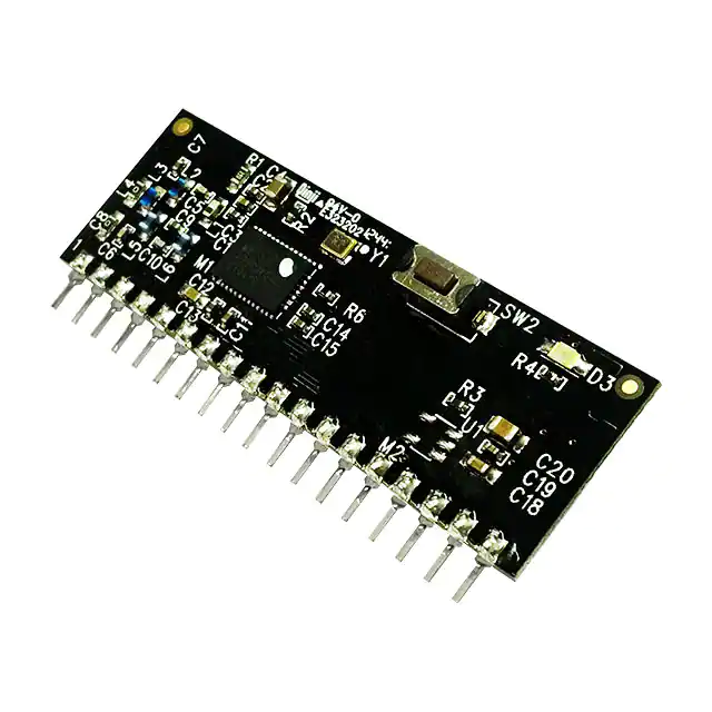
BRAVO
SmartRadio Telemetry Module
Features
•
8 Channel transceiver module
•
Range up to 1,000 metres
•
8 Digital input/outputs
•
Receiver outputs mirror
transmitter inputs
•
Minimal external components
•
Secure data protocol
•
Ultra low power 1.8—3.6V
•
Easy pairing process
•
One to one and one to many operation
•
869.5 / 915MHz* operating versions
•
+13dBm transmit power
Applications
•
Remote Control
•
Single in line module
•
Remote Networking
•
Incorporates Self Test Mode
•
Remote Switching
•
CE compliant for licence free use
•
Remote Traffic Lights
•
FCC Approved for use in USA (TBC)*
Description
The BRAVO-T telemetry module provides a reliable transceiver based industrial
remote switch with up to 1,000 metres range. Two or more modules may be
combined to provide a simple or complex network of radio switches.
Ordering Information
Part No
BRAVO-T868
BRAVO-T915 (TBC)*
Description
Radio telemetry module SIL package 868MHz
Radio telemetry module SIL package 915MHz (TBC)*
DS-BRAVO-9
�BRAVO Telemetry Module
Pin-out
Bravo
LED
ANT
I/O 1
I/O 2
LRN SW
LRN LED
I/O 3
I/O 4
I/O 5
NC
9 10 11 12 13 14 15 16 17 18
NC
8
Vcc
7
GND
6
I/O 8
5
I/O 7
4
W-DOG
3
I/O 6
2
Tx / NRX
1
GND
Learn
Switch
Pin Description
Pin No
Name
Direction
Description
1
ANT
In
Antenna input/output 50ohm impedance
2, 15
GND
In
Connect to ground
In / Out
When configured as transmitter:Active low
Digital inputs: high impedance inputs
When configured as receiver: Active High
Digital outputs: LVCMOS output drive
3, 4, 7, 8,
9, 11, 12
14
I/O1-8
5
LRN SW
In
Learn switch input: Normally ‘high’ momentary
connect to Ground to enter Learn Mode.
If on board switch or to be used this input can
be left unconnected
6
LRN LED
Out
Optional LED drive output Mirrors on-board LED
10
TX/RX
In
Connect to Vcc : Module is a transmitter
Connect to GND : Module is a receiver
13
W-DOG
In / Out
Transmitter= Input
Connect to Vcc : Watchdog is disabled
Connect to GND : Watchdog is enabled
Receiver= Output
High : Watchdog is healthy
Low : Watchdog Fault!
16
Vcc
In
Supply voltage
17
N/C
N/A
Leave unconnected
NC
In
TX MODE ONLY
MOM/
LTCH
In
In RX MODE ONLY
Momentary mode pull pin low - Connect to GND
LATCH mode pull pin high - Connect to VCC
18
General description of operation
Each module can be set to act as a ‘transmitter’ or ‘receiver’ A telemetry system is achieved when
two modules are paired together, as transmitter (BRAVO-Tx) and receiver (BRAVO-Rx).
Each time any input changes on the BRAVO-Tx, it will transmit the input status to the paired BRAVO
-Rx(s). The BRAVO-Rx(s) which will set their outputs to match the BRAVO-Tx input. After each state
change the modules will return to sleep mode.
Note: All of the 8 channels are common to all modules in a system
Example: If you are using a system with two or many Bravo modules each channel be will common to
all modules ie. if you change state on transmitter input 8, then all receiver output 8’s will also
change state.
DS-BRAVO-9
�BRAVO Telemetry Module
BRAVO Configured as a TRANSMITTER
1.
Operation
When configured as a transmitter the BRAVO module will automatically default to low power
sleep mode until any input state change takes place.
On receipt of an input state change the BRAVO-Tx will transmit a packet showing the state of
changed input/s (multiple input changes may take place simultaneously).
1.1 Watchdog
If watchdog is enabled the Bravo-Tx will transmit a background packet containing the current
status of the inputs every 5 minutes.
1.2 Digital Inputs
High impedance inputs, LVCMOS / LVTTL compatible, 5V tolerant.
Can be connected directly to CMOS/TTL logic or switch inputs connected to 0V or VCC
A change on the input will cause the BRAVO-Tx to wake, read all inputs and initiate RF
transmission.
Transmitter Application circuit example
BRAVO
LED
LEARN Sw
ANT
1
2
3
4
5
6
7
8
9
10 11 12 13 14 15 16 17 18
Vcc
GND
Input 1
Input 2
Input 3
Input 4
Input 5
Input 6
Input 7
Input 8
Description:
This example shows a BRAVO module configured as a transmitter with all 8 inputs connected
and watchdog disabled.
Notes:
All input switches would need to be connected to GND to activate.
DS-BRAVO-9
�BRAVO Telemetry Module
BRAVO Configured as a RECEIVER
Watchdog
BRAVO-Rx will await a Watchdog signal from a paired BRAVO-Tx module. When the Watchdog signal is received, the watchdog output will be maintained active high. If no watchdog
signal is received in any 30minute period then the BRAVO-Rx will drop the Watchdog output.
Other outputs are unaffected.
Digital outputs
Active high LVCMOS / LVTTL compatible outputs. Can be connected directly to CMOS/TTL
logic or drive.
Receiver example application circuit
BRAVO
LED
LEARN Sw
ANT
1
2
3
4
5
6
7
8
9 10 11 12 13 14 15 16 17 18
Vcc
GND
Output
Output
Output
Output
Output
Output
Output
Output
8
7
6
5
4
3
2
1
Description:
This example shows a BRAVO module configured as a receiver with all 8 outputs connected
and watchdog disabled.
Note: The external learn switch and LED are also not fitted in this example.
Optional external learn switch and LED example circuit
5
Learn
Switch
6
560R
Learn
LED
Vcc
DS-BRAVO-9
�BRAVO Telemetry Module
Pairing Process Bravo-Tx to Bravo-RX
Each BRAVO module has a unique serial number identity. They may be paired together using the
LEARN button/input so that they operate in systems in: one:one, one:many and many:one formats.
Each BRAVO-Rx can store 70 BRAVO-Tx identities.
Note: “Watchdog” should not be enabled for many to one systems.
3.1
Pairing process :
1. Briefly press the “LEARN” switch (or activate LEARN input) on the BRAVO
2. After you release the learn button, the LEARN LED will flash once
3. This shows that output 1 is selected.
4. Press the LEARN button again, after it is released the Learn LED will flash twice,
Continue in the same way to select outputs up to 8.
5. With your chosen output selected, briefly activate the input that you wish
to pair.
6. The LEARN LED will flash quickly to show that pairing is complete.
7. Repeat the process to all required pairings
Pairing Process Bravo-RX to Handheld Transmitter
When pairing the BRAVO as a receiver to a handheld transmitter, such as our FOBBER or ELITE.
The pairing process is completed manually (meaning you can pair any transmitter button, to any
desired I/O).
3.1 Pairing process:
1. Briefly press the “LEARN” switch (or activate LEARN input) on the BRAVO
2. After you release the learn button, the LEARN LED will flash once
3. This shows that output 1 is selected.
4. Press the LEARN button again, after it is released the Learn LED will flash twice,
Continue in the same way to select outputs up to 8.
5. With your chosen output selected, briefly press the button on the handset that you
wish to pair.
6. The LEARN LED will flash quickly to show that pairing is complete.
7. Repeat the process to all required pairings.
3.2 Paring process: ERASE:
1. Press and Hold ‘LEARN’ switch (or input) on the BRAVO for more than 10 seconds.
2. The LEARN LED will start flashing to show that erase is complete
3. Release the LEARN switch.
Notes: The maximum number of pairings is 15. One pairing is counted as a single button
output association Pairings can be on one or many handsets.
3.3
LED indication of the pairing process is given by:
Mode
Normal operation
Learn mode
(BRAVO-Rx only)
LED
Description
Flickering ON
Module is transmitting or receiving data
OFF
No RF data is being transmitted/received
Flashing at low
speed
BRAVO-RX Learn button pressed: module is
searching for another to pair with.
Learn mode times out after 10 seconds
Flashing at high
speed for 3secs
BRAVO-Rx pairing successful
DS-BRAVO-9
�BRAVO Telemetry Module
Operational application examples
Application example one:one operation
Input 1 - 8
Bravo
Transmitter
Transmit Signal
Bravo
Receiver
Output 1 - 8
In this application the outputs at the receiver will match the inputs at the transmitter.
Application example: one:many operation
Input 1 - 8
Bravo
Transmitter
Transmit Signal
Bravo
Receiver
Input 1 - 8
Bravo
Receiver
Input 1 - 8
Bravo
Receiver
Input 1 - 8
In this application the outputs at each of the receivers will track the inputs at the transmitter.
DS-BRAVO-9
�BRAVO Telemetry Module
Mechanical Dimensions
40.5mm
34.5mm
17mm
10.5mm
48mm
1
2
3
4mm
2.33mm
4
5
6
7
8
9 10 11 12 13 14 15 16 17 18
2.54mm
Notes
1. Pins 2.54mm pitch
2. Pin Dims 0.4mm sq
3. All dims in mm
Range Considerations
The antenna choice and position directly affects the system range, keep it clear of any large
metal parts. The best position is protruding vertically from the top of the product. This is often
not desirable for practical reasons and thus a compromise may be needed. Note that the space
around the antenna is as important as the antenna itself. All radio systems are dependent on a
radio signal being received through airspace.
The range quoted is the optimal in direct line of sight without obstacles and in good atmospheric
conditions.
Range is affected by many things, for example local environmental conditions, atmospheric
conditions, interference from other radio transmitters. For evaluating the local environment
please see our RF Meter (DS006).
In very worse case applications the range quoted may be reduced dramatically below
the optimal range stated.
Self Test Mode
The Bravo Module incorporates a self test which is initiated by applying power with the learn
Button being held down.
The Bravo Module then performs the following functions;
1.
All I/O are set to outputs and are operated
2.
in a traffic light sequence 0 to 8 to 0 again.
3.
4 on 4 off sequence
4.
Transmits a full power RF signal for 10 seconds and operates the Learn LED
5.
Enters RSSI (Received signal Strength) mode where outputs 1-8 are activated as a bar
graph type output according to the strength of a valid RF signal received (from any
carrier operating at the appropriate frequency (869.50MHz or 915MHz)
6.
A Reset will be required to Exit
DS-BRAVO-9
�BRAVO Telemetry Module
Technical Specifications
Absolute Maximums:
Temperature Range: Storage –50 to +125oC.
DC Characteristics
Parameter
Min
Max
Units
Supply Voltage
-0.3
3.6
V
5.8
V
Vcc+3.6
V
Max Input power (through RX antenna)
+5
dBm
Max Current Sourced / Sunk (Per I/O)
10
mA
Max Current Sourced / Sunk (Total)
20
mA
Voltage on any Input
Vcc > 2.2V
Vcc < 2.2V
DC Characteristics
Parameter
Min
Supply Voltage
Operating Temperature
Typical
Max
Units
1.8
3.6
V
-40
+85
C
o
BRAVO- Tx Supply Current:
When Transmitting
When sleeping
30
mA
6
uA
24
mA
BRAVO- Rx Supply Current:
When Receiving
AC Characteristics
Parameter
Min
Operating Frequency
Typical
Max
869.5
Operating Freq for 915Mhz version
Operating Temperature
Units
MHz
915.00
915.27
-40
+85
MHz
C
o
BRAVO- Tx Output Power
+13
dBm
BRAVO- Tx—Rx FSK Raw RF Data Rate
9.6
Kbps
BRAVO- Rx Sensitivity
-121
DS-BRAVO-9
dBm
�BRAVO Telemetry Module
Simplified Declaration of Conformity (RED)
BG - С настоящото RF Solutions Limited декларира, че този тип радиосъоръжение дефинирани в този документ е в съответствие с Директива 2014/53/ЕС.
Цялостният текст на ЕС декларацията за съответствие може да се намери на следния интернет адрес: www.rfsolutions.co.uk
CS -Tímto RF Solutions Limited prohlašuje, že typ rádiového zařízení definované v tomto dokumentu je v souladu se směrnicí 2014/53/EU.
Úplné znění EU prohlášení o shodě je k dispozici na této internetové adrese: www.rfsolutions.co.uk
DA - Hermed erklærer RF Solutions Limited , at radioudstyrstypen defineret i dette dokument er i overensstemmelse med direktiv 2014/53/
EU. EU-overensstemmelseserklæringens fulde tekst kan findes på følgende internetadresse: www.rfsolutions.co.uk
DE - Hiermit erklärt RF Solutions Limited , dass der Funkanlagentyp in diesem Dokument definiert der Richtlinie 2014/53/EU entspricht. Der
vollständige Text der EU-Konformitätserklärung ist unter der folgenden Internetadresse verfügbar: www.rfsolutions.co.uk
EL - Με την παρούσα ο/η RF Solutions Limited , δηλώνει ότι ο ραδιοεξοπλισμός ορίζεται σε αυτό το έγγραφο πληροί την οδηγία 2014/53/ΕΕ. Το πλήρες
κείμενο της δήλωσης συμμόρφωσης ΕΕ διατίθεται στην ακόλουθη ιστοσελίδα στο διαδίκτυο: www.rfsolutions.co.uk
EN - Hereby, RF Solutions Limited declares that the radio equipment type defined within this document is in compliance with Direct ive
2014/53/EU. The full text of the EU declaration of conformity is available at the following internet address: www.rfsolutions.co.uk
ES - Por la presente, RF Solutions Limited declara que el tipo de equipo radioeléctrico definido dentro de este documento es confo rme con la
Directiva 2014/53/UE. El texto completo de la declaración UE de conformidad está disponible en la dirección Internet siguient e:
www.rfsolutions.co.uk
ET -Käesolevaga deklareerib RF Solutions Limited , et käesolev raadioseadme tüüp määratletud selles dokumendis vastab direktiivi 2014/53/
EL nõuetele. ELi vastavusdeklaratsiooni täielik tekst on kättesaadav järgmisel internetiaadressil: www.rfsolutions.co.uk
FI -RF Solutions Limited vakuuttaa, että radiolaitetyyppi määratletud selles dokumendis on direktiivin 2014/53/EU mukainen. EUvaatimustenmukaisuusvakuutuksen täysimittainen teksti on saatavilla seuraavassa internetosoitteessa: www.rfsolutions.co.uk
FR - Le soussigné, RF Solutions Limited , déclare que l'équipement radioélectrique du type défini dans ce document est conforme à la di-
rective 2014/53/UE. Le texte complet de la déclaration UE de conformité est disponible à l'adresse internet suivante: www.rfsolutions.co.uk
HR - RF Solutions Limited ovime izjavljuje da je radijska oprema tipa definirani u ovom dokumentu u skladu s Direktivom 2014/53/EU. Cjeloviti
tekst EU izjave o sukladnosti dostupan je na sljedećoj internetskoj adresi: www.rfsolutions.co.uk
HU - RF Solutions Limited igazolja, hogy a dokumentumban meghatározottak szerint típusú rádióberendezés megfelel a 2014/53/EU
irányelvnek. Az EU-megfelelőségi nyilatkozat teljes szövege elérhető a következő internetes címen: www.rfsolutions.co.uk
IT - Il fabbricante, RF Solutions Limited , dichiara che il tipo di apparecchiatura radio definito all'interno di questo documento è conforme alla
direttiva 2014/53/UE. Il testo completo della dichiarazione di conformità UE è disponibile al seguente indirizzo Internet: ww w.rfsolutions.co.uk
LT - Aš, RF Solutions Limited , patvirtinu, kad radijo įrenginių tipas apibrėžta šiame dokumente atitinka Direktyvą 2014/53/ES. Visas ES atitikties deklaracijos tekstas prieinamas šiuo interneto adresu: www.rfsolutions.co.uk
LV - Ar šo RF Solutions Limited deklarē, ka radioiekārta kas definēts šajā dokumentā atbilst Direktīvai 2014/53/ES. Pilns ES atbilstības
deklarācijas teksts ir pieejams šādā interneta vietnē: www.rfsolutions.co.uk
MT - B'dan, RF Solutions Limited , niddikjara li dan it-tip ta' tagħmir tar-radju definit f'dan id-dokument huwa konformi mad-Direttiva 2014/53/
UE. It-test kollu tad-dikjarazzjoni ta' konformità tal-UE huwa disponibbli f'dan l-indirizz tal-Internet li ġej: www.rfsolutions.co.uk
NL - Hierbij verklaar ik, RF Solutions Limited , dat het type radioapparatuur gedefinieerd in dit document conform is met Richtlijn 2014/53/
EU. De volledige tekst van de EU-conformiteitsverklaring kan worden geraadpleegd op het volgende internetadres: www.rfsolutions.co.uk
PL - RF Solutions Limited niniejszym oświadcza, że typ urządzenia radiowego zdefiniowane w tym dokumencie jest zgodny z dyrektywą
2014/53/UE. Pełny tekst deklaracji zgodności UE jest dostępny pod następującym adresem internetowym: www.rfsolutions.co.uk
PT - O(a) abaixo assinado(a) RF Solutions Limited declara que o presente tipo de equipamento de rádio definido neste documento est á em
conformidade com a Diretiva 2014/53/UE. O texto integral da declaração de conformidade está disponível no seguinte endereço de Internet:
www.rfsolutions.co.uk
RO - Prin prezenta, RF Solutions Limited declară că tipul de echipamente radio definit în acest document este în conformitate cu Directiva
2014/53/UE. Textul integral al declarației UE de conformitate este disponibil la următoarea adresă internet: www.rfsolutions.co.uk
SK - RF Solutions Limited týmto vyhlasuje, že rádiové zariadenie typu definované v tomto dokumente je v súlade so smernicou 2014/53/EÚ.
Úplné EÚ vyhlásenie o zhode je k dispozícii na tejto internetovej adrese: www.rfsolutions.co.uk
SL - RF Solutions Limited potrjuje, da je tip radijske opreme opredeljeno v tem dokumentu skladen z Direktivo 2014/53/EU. Celotno besedilo
izjave EU o skladnosti je na voljo na naslednjem spletnem naslovu: www.rfsolutions.co.uk
SV - Härmed försäkrar RF Solutions Limited att denna typ av radioutrustning definieras i detta dokument överensstämmer med direktiv
2014/53/EU. Den fullständiga texten till EU-försäkran om överensstämmelse finns på följande webbadress: www.rfsolutions.co.uk
RF Solutions Ltd. Recycling Notice
Meets the following EC Directives:
DO NOT Discard with normal waste, please recycle.
ROHS Directive 2011/65/EU and amendment 2015/863/EU
Specifies certain limits for hazardous substances.
WEEE Directive 2012/19/EU
Waste electrical & electronic equipment. This product must be disposed of through a licensed WEEE collection point.
RF Solutions Ltd., fulfills its WEEE obligations by membership of an approved compliance scheme, environment agency
registration number WEE/JB0104WV.
Disclaimer:
Whilst the information in this document is believed to be correct at the time of issue, RF Solutions Ltd does not accept any liability whatsoever for its accuracy, adequacy or completeness. No express or implied warranty or representation is given relating to the information contained in this document. RF Solutions Ltd reserves the right to make changes and improvements to the product(s) described herein without
notice. Buyers and other users should determine for themselves the suitability of any such information or products for their own particular
requirements or specification(s). RF Solutions Ltd shall not be liable for any loss or damage caused as a result of user’s o wn determination
of how to deploy or use RF Solutions Ltd’s products. Use of RF Solutions Ltd products or components in life support and/or safety applications is not authorised except with express written approval. No licences are created, implicitly or otherwise, under any of RF Solutions
Ltd’s intellectual property rights. Liability for loss or damage resulting or caused by reliance on the information contained herein or from the
use of the product (including liability resulting from negligence or where RF Solutions Ltd was aware of the possibility of such loss or damage
arising) is excluded. This will not operate to limit or restrict RF Solutions Ltd’s liability for death or personal injury re sulting from its negligence.
�


 工商网监
湘ICP备2023018690号
工商网监
湘ICP备2023018690号
