January 2023
er
put
Com
e
il
b
o
M
TV
MULTILAYER CERAMIC
CAPACITORS
�MULTILAYER CERAMIC
CAPACITORS
Interactive User Guide
Samsung Electro-Mechanics’ MLCC Catalog was produced as an INTERACTIVE PDF that allows transferring
to related webpages for better understanding of the content. Click ‘HOME,’ ‘CONTENTS,’ OR ‘GO BACK TO
PAGE’ as needed, and it is also possible to ‘PRINT’ the pages. If you click the icon at the top of the page, it is
possible to view a specific page of choice.
By clicking this icon, you can
By clicking this icon, you can
jump directly to the cover page of
jump directly to the Table of
this catalog.
Contents.
By clicking this icon, you can
By clicking this icon, you can set
jump directly to the previous page.
and print pages of your choice.
�C O N
T
E
N
T S
04 Explanation of Ceramic Capacitors
06 Part Numbering
09 Reliability Level Description
10 Normal Capacitors_Standard
77 Normal Capacitors_High Level Ⅰ
96 Normal Capacitors_High Level Ⅱ
100 Land Side Capacitors (LSC)
102 High Bending Strength Capacitors
104 Low Acoustic Noise Capacitors
108 Low ESL Capacitors
112 Array Type Capacitors
113 Application Guide
117 Reliability Test Conditions
123 Packaging Specifications
129 Caution/Notice
150 Disclaimer & Limitation of Use and Applications
151 Component Sales Offices/Manufacturing Sites
� Explanation of Ceramic Capacitors
Part Numbering
Reliability Level Description
Normal Capacitors_Standard
Land Side Capacitors (LSC)
Reliability Test Conditions
Low Acoustic Noise Capacitors
Caution/Notice
High Bending Strength Capacitors
Packaging Specifications
Low ESL Capacitors
Normal Capacitors_High Level Ⅰ
Disclaimer & Limitation of Use and Applications
Array Type Capacitors
Normal Capacitors_High Level Ⅱ
Component Sales Offices/
Application Guide
Manufacturing Sites
Explanation of Ceramic Capacitors
Normal Capacitors
Normal Capacitors
Standard
High Level Ⅰ
High Level Ⅱ
Improved Reliability
Reinforced Reliability
(65℃, 90%RH, 1Vr, 500H)
(85℃, 85%RH, 1Vr, 1000H)
LSC Capacitors
Lower thickness and space saving
LSC
High Bending Strength Capacitors
More Resistant to stress caused by board bending
High-bending
Strength
MULTILAYER CERAMIC CAPACITORS
04
� Explanation of Ceramic Capacitors
Part Numbering
Reliability Level Description
Normal Capacitors_Standard
Land Side Capacitors (LSC)
Reliability Test Conditions
Low Acoustic Noise Capacitors
Caution/Notice
High Bending Strength Capacitors
Low ESL Capacitors
Normal Capacitors_High Level Ⅰ
Array Type Capacitors
Normal Capacitors_High Level Ⅱ
Application Guide
Packaging Specifications
Disclaimer & Limitation of Use and Applications
Component Sales Offices/
Manufacturing Sites
Explanation of Ceramic Capacitors
Low Acoustic Noise Capacitors
A solution that effectively reduces audible noise
Low Acoustic
Noise
Low ESL Capacitors
Space Saving & High Speed Energy Transfer
Low ESL
Array Type Capacitors
High Performance & Space Saving
Array Type
MULTILAYER CERAMIC CAPACITORS
05
�Explanation of Ceramic Capacitors
Land Side Capacitors (LSC)
Reliability Test Conditions
Reliability Level Description
Low Acoustic Noise Capacitors
Caution/Notice
High Bending Strength Capacitors
Part Numbering
Normal Capacitors_Standard
Low ESL Capacitors
Normal Capacitors_High Level Ⅰ
CL 10
1
1
A 106 M
2
3
4
5
Disclaimer & Limitation of Use and Applications
Array Type Capacitors
Normal Capacitors_High Level Ⅱ
Part Numbering
Packaging Specifications
Component Sales Offices/
Application Guide
Q
8
6
7
Manufacturing Sites
N
N
8
N
9
C
10
11
SERIES CODE
CL = Multilayer Ceramic Capacitors
2
3
SIZE CODE
Code
mm (inch)
Code
mm (inch)
Code
mm (inch)
Code
mm (inch)
R1
0201(008004)
02
0402 (01005)
03
05
0603 (0201)
1005 (0402)
10
21
31
32
1608 (0603)
2012 (0805)
3216 (1206)
3225 (1210)
42
43
55
L5
4520 (1808)
4532 (1812)
5750 (2220)
0510(0204)
L6
01
19
0610(0304)
0816(0306)
1209(0503)
DIELECTRIC CODE
Class Ⅰ (Temperature Compensation)
Symbol
EIA Code
Operation Temperature Range (℃)
Temperature Coefficient Range (ppm/℃)
C
G
C0G
X8G
-55 ~ +125
-55 ~ +150
0 ± 30
0 ± 30
Class Ⅱ (High Dielectric Constant)
4
Symbol
EIA Code
Operation Temperature Range (℃)
Capacitance Change (ΔC %)
A
X
W
B
K
Y
Z
F
M
E
J
X5R
X6S
X6T
X7R
X7R(S)
X7S
X7T
Y5V
X8M
X8L
JIS-B
-55 ~ +85
-55 ~ +105
-55 ~ +105
-55 ~ +125
-55 ~ +125
-55 ~ +125
-55 ~ +125
-30 ~ +85
-55 ~ +150
-55 ~ +150
-25 ~ +85
±15
±22
-33 ~ +22
±15
±15
±22
-33 ~ +22
-82 ~ +22
-50 ~ +50
-40 ~ +15
±10
CAPACITANCE CODE
For Values <10㎊, Letter R denotes decimal point
Capacitance expressed in ㎊. 2 significant digits plus number of zeros.
6
example) 1R5 =1.5㎊
example) 106=10×10 =10,000,000㎊
5
CAPACITANCE TOLERANCE CODE
Code
Tolerance
Code
Tolerance
Code
Tolerance
Code
Tolerance
N
A
B
C
±0.03㎊
±0.05㎊
±0.1㎊
±0.25㎊
H
L
D
F*
+0.25㎊
-0.25㎊
±0.5㎊
±1㎊
F
G
J
U
±1%
±2%
±5%
+5%
V
K
M
Z
-5%
±10%
±20%
-20, +80%
* For Values<10pF, F=±1pF / Values≥10pF, F=±1%
MULTILAYER CERAMIC CAPACITORS
06
�Explanation of Ceramic Capacitors
Land Side Capacitors (LSC)
Reliability Test Conditions
Reliability Level Description
Low Acoustic Noise Capacitors
Caution/Notice
High Bending Strength Capacitors
Part Numbering
Normal Capacitors_Standard
Packaging Specifications
Low ESL Capacitors
Normal Capacitors_High Level Ⅰ
Disclaimer & Limitation of Use and Applications
Array Type Capacitors
Normal Capacitors_High Level Ⅱ
Component Sales Offices/
Application Guide
Manufacturing Sites
Part Numbering
Series
Nominal Capcitance
E-3
1.0
E-6
E-12
E-24
6
7
2.2
1.0
1.5
4.7
2.2
3.3
4.7
6.8
1.0
1.2
1.5
1.8
2.2
2.7
3.3
3.9
4.7
5.6
6.8
8.2
1.0
1.2
1.5
1.8
2.2
2.7
3.3
3.9
4.7
5.6
6.8
8.2
1.1
1.3
1.6
2.0
2.4
3.0
3.6
4.3
5.1
6.2
7.5
9.1
RATED VOLTAGE CODE
Code
Voltage
Code
Voltage
Code
Voltage
Code
Voltage
S
2.5Vdc
O
16Vdc
C
100Vdc
G
500Vdc
R
4.0Vdc
A
25Vdc
D
200Vdc
H
630Vdc
Q
6.3Vdc
L
35Vdc
E
250Vdc
I
1kVdc
P
10Vdc
B
50Vdc
F
350Vdc
J
2kVdc
K
3kVdc
THICKNESS CODE
Size mm (inch)
Code
Thickness
Tolerance
Code
Thickness
Tolerance
0402 (01005)
2
0.20
±0.02
C
0.85
±0.10*
0603 (0201)
3
0.30
±0.03
9
0.90
±0.10*
3
0.30
±0.03*
F
1.25
±0.20
5
0.50
±0.05
S
1.35
±0.15*
5
0.50
+0.0/-0.1*
H
1.60
±0.20
8
0.80
±0.10
U
1.80
±0.20*
A
0.65
±0.10
I
2.00
±0.20
C
0.85
±0.10*
J
2.50
±0.20
C
0.85
±0.10
V
2.50
±0.30
M
1.15
±0.10
F
1.25
±0.10
Q
1.25
Y
1005 (0402)
1608 (0603)
2012 (0805)
3216 (1206)
Size mm (inch)
3225 (1210)
F
1.25
±0.20
G
1.40
±0.20
±0.15
I
2.00
±0.20
1.25
±0.20
F
1.25
±0.20
C
0.85
±0.15
H
1.60
±0.20
C
0.85
±0.10*
I
2.00
±0.20
E
1.10
±0.15
J
2.50
±0.20
E
1.10
±0.10*
L
3.20
±0.30
4520 (1808)
4532 (1812)
P
1.15
±0.10*
H
1.60
±0.20
M
1.15
±0.15
I
2.00
±0.20
F
1.25
±0.15
J
2.50
±0.20
H
1.6
±0.20
L
3.20
±0.30
5750 (2220)
* Mark is only applicable to “L”,”Y”,”F”, 12th code in part number.
MULTILAYER CERAMIC CAPACITORS
07
�Explanation of Ceramic Capacitors
Land Side Capacitors (LSC)
Reliability Test Conditions
Reliability Level Description
Low Acoustic Noise Capacitors
Caution/Notice
High Bending Strength Capacitors
Part Numbering
Normal Capacitors_Standard
Packaging Specifications
Low ESL Capacitors
Normal Capacitors_High Level Ⅰ
Disclaimer & Limitation of Use and Applications
Array Type Capacitors
Normal Capacitors_High Level Ⅱ
Component Sales Offices/
Application Guide
Manufacturing Sites
Part Numbering
8
9
INNER ELECTRODE/TERMINATION/PLATING CODE
Code
Thickness division
Inner electrode
Termination
Plating material
N
Normal
Ni
Cu
Ni / Sn _100%
G
Normal
Cu
Cu
Ni / Sn _100%
S
Normal
Ni
Metal Epoxy
Ni / Sn _100%
C
Normal
Ni
Control Code
Ni / Sn _100%
L
Low profile
Ni
Cu
Ni / Sn _100%
Y
Low profile
Ni
Metal Epoxy
Ni / Sn _100%
Z
Normal
Ni
Metal Epoxy
Ni / Sn _100%
F
Low profile
Ni
Metal Epoxy
Ni / Sn _100%
PRODUCT CODE OR SIZE CONTROL CODE
N=Normal
A=Array (2-element)
B=Array (4-element)
L=LICC (Low Inductance Ceramic Capacitor)
J=SLIC (Super Low Inductance Capacitor)
(Unit : mm (inch))
Size
0402 (01005)
0603 (0201)
1005 (0402)
1608 (0603)
S
±0.03
±0.05
±0.07
±0.07
Q
±0.05
±0.07
±0.10
±0.15
±0.15
R
±0.07
±0.09
±0.15
±0.20
±0.20
U
±0.09
±0.20
±0.25
±0.25
Z
±0.40
±0.30
±0.30
9
±0.30
Code
10
2012 (0805)
3216 (1206)
±0.30
CONTROL CODE
N= Reserved for future use
11
PACKAGING CODE
Cardboard Tape (paper)
Embossed Tape (plastic)
Code
Taping Type
Code
Taping Type
8/C/H
Normal, 7"reel (Quantity option)
E/G
Normal, 7"reel (Quantity option)
J
1mm Pitch, 7"reel
R
Chip aligned for horizontal, 7"reel
Z
Chip aligned for horizontal, 7"reel
W
Chip aligned for vertical, 7"reel
Y
Chip aligned for vertical, 7"reel
S
Normal, 10"reel
O
Normal, 10"reel
F
Normal, 13"reel (Quantity option)
3/D/L
Normal, 13"reel (Quantity option)
2
1mm Pitch, 13"reel
7
Chip aligned for vertical, 13"reel
MULTILAYER CERAMIC CAPACITORS
08
�Explanation of Ceramic Capacitors
Part Numbering
Reliability Level Description
Normal Capacitors_Standard
Normal Capacitors_High Level Ⅰ
Normal Capacitors_High Level Ⅱ
Land Side Capacitors (LSC)
Reliability Test Conditions
Low Acoustic Noise Capacitors
Caution/Notice
High Bending Strength Capacitors
Packaging Specifications
Low ESL Capacitors
Disclaimer & Limitation of Use and Applications
Array Type Capacitors
Component Sales Offices/
Application Guide
Manufacturing Sites
Reliability Level Description
Reliability Level
Standard
High Level Ⅰ
High Level Ⅱ
AEC-Q200
AEC-Q200
-
-
-
-
Humidity Test
40%, 95%RH, 1Vr,
500H
65%, 90%RH, 1Vr,
500H
85%, 85%RH, 1Vr,
1000H
85%, 85%RH,
1.3~1.5Vr, 1000H
High Temp Load
Test
Max. Temp, 1.5Vr,
1000h
Max. Temp, 1.5Vr,
1000h
Max. Temp, 1.5Vr,
1000h
Max. Temp,
2Vr, 1000h
Board Flex
1mm
1mm
2mm
2mm
Temp. Cycling
5cycle
5cycle
1000cycle
1000cycle
1. The part marked ‘derating’ is less than 150% of rated voltage in the durability and operational life test.
2. Some of the parts are applicable in rated voltage × 150% or × 120%. Please refer to individual specifications.
3. Some of parts are 3mm bending guaranteed. Please refer to individual specifications.
MULTILAYER CERAMIC CAPACITORS
09
�Explanation of Ceramic Capacitors
Land Side Capacitors (LSC)
Reliability Test Conditions
Reliability Level Description
Low Acoustic Noise Capacitors
Caution/Notice
Part Numbering
Normal Capacitors_Standard
Normal Capacitors_High Level Ⅰ
Normal Capacitors_High Level Ⅱ
High Bending Strength Capacitors
Packaging Specifications
Low ESL Capacitors
Disclaimer & Limitation of Use and Applications
Array Type Capacitors
Component Sales Offices/
Application Guide
Normal Capacitors_Standard
Manufacturing Sites
Normal
Standard
Features
�A Normal MLCC temporarily charges and reduces noise in electronic circuits, and is the most broadly available chip-type capacitor.
�The product line allows realization of various sizes and a wide range of capacitance.
�It also has the structural capacity to mount chips on a PCB at a high speed.
❶ Ceramic Body
❷ Electrode (Ni/Cu*)
Wide Selection of Size & Wide Capacitance Range
❸ Plating (Ni)
❹ �Termination
Products offered with various sizes and a wide range of capacities
(Cu or Cu+Metal Epoxy)
⑤ Plating (Sn)
Excellent DC Bias Characteristics
Capacitor with Excellent DC Bias Characteristics
High Speed Automatic Chip Placement on PCBs
* Internal Cu electrode is only applied to limited products.
Chip Mountable on PCB at High Speed
Application
�Smart Phone, PC, HDD/SSD Board, Tablet, Display, Game Machine, DC-DC Converter
Structure and Dimensions
BW
T
W
L
Size Code
Dimension (mm)
EIA (inch)
L
W
T
BW
R1
0.25±0.013
0.125±0.013
0.125±0.013
0.075±0.025
02
0.40±0.02
0.20±0.02
0.20±0.02
0.1±0.03
01005
05025
0.50±0.025
0.25±0.025
0.25±0.025
0.13±0.04
015008
0.60±0.03
0.30±0.03
0.30±0.03
0.60±0.05
0.30±0.05
0.30±0.05
0.60±0.09
0.30±0.09
0.50±0.05
0.15±0.05
0201
0.60±0.09
0.30±0.09
0.30±0.09
1.00±0.05
0.50±0.05
0.50±0.05
1.00±0.05
0.50±0.05
0.30±0.03
1.00±0.05
0.50±0.05
0.20±0.02
1.00±0.07
0.50±0.07
0.50±0.07
1.00±0.10
0.50±0.10
0.50±0.10
1.00±0.10
0.50±0.10
0.30±0.03
1.00±0.15
0.50±0.15
0.50±0.15
0.25±0.10
0402
1.00±0.15
0.50±0.15
0.30±0.03
1.00±0.20
0.50±0.20
0.50±0.20
1.00±0.20
0.50±0.25
0.70±0.10
1.00±0.20
0.50±0.20
0.60±0.20
1.00±0.20
0.50±0.20
0.50±0.05
1.15±0.05
0.70±0.05
0.70±0.05
03
05
MULTILAYER CERAMIC CAPACITORS
008004
10
�Explanation of Ceramic Capacitors
Land Side Capacitors (LSC)
Reliability Test Conditions
Reliability Level Description
Low Acoustic Noise Capacitors
Caution/Notice
Part Numbering
Normal Capacitors_Standard
Normal Capacitors_High Level Ⅰ
Normal Capacitors_High Level Ⅱ
High Bending Strength Capacitors
Low ESL Capacitors
Array Type Capacitors
Application Guide
Packaging Specifications
Disclaimer & Limitation of Use and Applications
Component Sales Offices/
Manufacturing Sites
Normal Capacitors_Standard
Size Code
10
21
31
32
43
Dimension (mm)
L
W
1.60±0.10
0.80±0.10
0.80±0.10
1.60±0.10
0.80±0.10
0.50+0.00/-0.10
1.60±0.15
0.80±0.15
0.80±0.15
1.60±0.20
0.80±0.20
0.80±0.20
1.60±0.20
0.80±0.20
0.80±0.20
1.60±0.20
0.80±0.20
0.70±0.20
1.60±0.25
0.80±0.25
0.70±0.10
1.60±0.25
0.80±0.25
0.80±0.25
1.60±0.30
0.80±0.30
0.70±0.10
1.60±0.30
0.80±0.30
0.80±0.30
1.60±0.30
0.80±0.30
0.50±0.30
1.80±0.10
1.00±0.10
0.70±0.10
2.00±0.10
1.25±0.10
0.65±0.10
2.00±0.10
1.25±0.10
0.85±0.10
2.00±0.10
1.25±0.10
0.90±0.10
2.00±0.10
1.25±0.10
1.25±0.10
2.00±0.15
1.25±0.15
0.85±0.10
2.00±0.15
1.25±0.15
1.25±0.15
2.00±0.20
1.25±0.20
0.70±0.10
2.00±0.20
1.25±0.20
0.80±0.10
2.00±0.20
1.25±0.20
0.85±0.10
2.00±0.20
1.25±0.20
0.90±0.10
2.00±0.20
1.25±0.20
1.10±0.10
2.00±0.20
1.25±0.20
1.25±0.20
3.20±0.15
1.60±0.15
0.85±0.15
3.20±0.15
1.60±0.15
1.25±0.15
3.20±0.20
1.60±0.20
0.85±0.10
3.20±0.20
1.60±0.20
0.90±0.10
3.20±0.20
1.60±0.20
1.15±0.10
3.20±0.20
1.60±0.20
1.15±0.15
3.20±0.20
1.60±0.20
1.60±0.20
3.20±0.30
2.50±0.20
0.85±0.10
3.20±0.30
2.50±0.20
1.25±0.20
3.20±0.30
2.50±0.20
1.35±0.15
3.20±0.30
2.50±0.20
1.40±0.20
3.20±0.30
2.50±0.20
1.60±0.10
3.20±0.30
2.50±0.20
1.60±0.20
3.20±0.30
2.50±0.20
1.80±0.20
3.20±0.30
2.50±0.20
2.50±0.20
3.20±0.30
2.50±0.20
2.00±0.20
3.20±0.40
2.50±0.30
2.50±0.20
3.20±0.40
2.50±0.30
2.50±0.30
4.50±0.40
3.20±0.30
1.60±0.20
MULTILAYER CERAMIC CAPACITORS
T
BW
EIA (inch)
0.30±0.20
0603
0.5+0.2/-0.3
0805
0.50±0.30
1206
0.60±0.30
1210
0.80±0.30
1812
11
�Explanation of Ceramic Capacitors
Land Side Capacitors (LSC)
Reliability Test Conditions
Reliability Level Description
Low Acoustic Noise Capacitors
Caution/Notice
Part Numbering
High Bending Strength Capacitors
Packaging Specifications
Low ESL Capacitors
Normal Capacitors_Standard
Normal Capacitors_High Level Ⅰ
Disclaimer & Limitation of Use and Applications
Array Type Capacitors
Normal Capacitors_High Level Ⅱ
Component Sales Offices/
Application Guide
Manufacturing Sites
Normal Capacitors_Standard
Capacitance Table (C0G)
Category
TC
Size mm
(inch)
0201 (008004)
0402 (01005)
0603 (0201)
1005 (0402)
1608 (0603)
Normal
C0G
(125℃)
2012 (0805)
3216 (1206)
3225 (1210)
MULTILAYER CERAMIC CAPACITORS
Rated
Voltage
(Vdc)
Capacitance
pF
0.1
1
10
nF
100
1
10
uF
100
1
10
100
Capacitance
Range
25
0.2pF - 0.8pF
6.3
100pF - 100pF
16
0.5pF - 100pF
25
12pF - 100pF
25
0.2pF - 100pF
50
10pF - 100pF
100
100pF - 100pF
16
100pF - 1nF
25
20pF - 1nF
50
3.3pF - 1nF
100
12pF - 1nF
16
1nF - 2.2nF
25
560pF - 4.7nF
50
4.7pF - 5.6nF
100
10pF - 3.9nF
200
220pF - 220pF
250
470pF - 470pF
25
3.3nF - 10nF
50
10pF - 15nF
100
12pF - 3.9nF
200
18pF - 1nF
250
1nF - 2.2nF
16
15nF - 120nF
25
10nF - 100nF
50
10pF - 47nF
100
20pF - 10nF
200
220pF - 1nF
250
2.2nF - 8.2nF
500
10pF - 2.2nF
630
10pF - 3.3nF
1000
10pF - 470pF
2000
15pF - 100pF
50
1.8nF - 22nF
100
33nF - 47nF
500
680pF - 1.8nF
630
1.8nF - 8.2nF
2000
100pF - 100pF
12
�Explanation of Ceramic Capacitors
Land Side Capacitors (LSC)
Reliability Test Conditions
Reliability Level Description
Low Acoustic Noise Capacitors
Caution/Notice
Part Numbering
High Bending Strength Capacitors
Packaging Specifications
Low ESL Capacitors
Normal Capacitors_Standard
Normal Capacitors_High Level Ⅰ
Disclaimer & Limitation of Use and Applications
Array Type Capacitors
Normal Capacitors_High Level Ⅱ
Component Sales Offices/
Application Guide
Manufacturing Sites
Normal Capacitors_Standard
Capacitance Table (X5R)
Category
TC
Size mm
(inch)
0201 (008004)
Rated
Voltage
(Vdc)
6.3
4
0402 (01005)
0502 (015008)
1005 (0402)
1608 (0603)
Normal
X5R
(85℃)
2012 (0805)
3216 (1206)
3225 (1210)
MULTILAYER CERAMIC CAPACITORS
0.1
1
10
nF
100
1
10
uF
100
1
10
100
Capacitance
Range
1nF - 10nF
100nF - 220nF
6.3
1nF - 1uF
10
1nF - 10nF
6.3
1uF - 1uF
4
0603 (0201)
Capacitance
pF
1uF - 4uF
6.3
15nF - 4.7uF
10
2.2nF - 2.2uF
16
100nF - 1uF
25
4.7nF - 330nF
35
220pF - 1.5nF
4
2.2uF - 22uF
6.3
100nF - 22uF
10
100nF - 10uF
16
100nF - 4.7uF
25
100nF - 4.7uF
35
1uF - 1uF
4
22uF - 47uF
6.3
1uF - 47uF
10
220nF - 22uF
16
470nF - 22uF
25
100nF - 10uF
35
1uF - 10uF
50
220nF - 2.2uF
4
47uF - 100uF
6.3
4.7uF - 47uF
10
1uF - 22uF
16
1uF - 22uF
25
1uF - 22uF
35
4.7uF - 4.7uF
50
1uF - 10uF
6.3
10uF - 100uF
10
10uF - 47uF
16
2.2uF - 22uF
25
3.3uF - 22uF
35
4.7uF - 4.7uF
50
1uF - 10uF
100
2.2uF - 2.2uF
6.3
22uF - 220uF
10
10uF - 100uF
16
10uF - 47uF
25
10uF - 22uF
35
4.7uF - 10uF
50
10uF - 10uF
13
�Explanation of Ceramic Capacitors
Land Side Capacitors (LSC)
Reliability Test Conditions
Reliability Level Description
Low Acoustic Noise Capacitors
Caution/Notice
Part Numbering
High Bending Strength Capacitors
Packaging Specifications
Low ESL Capacitors
Normal Capacitors_Standard
Normal Capacitors_High Level Ⅰ
Disclaimer & Limitation of Use and Applications
Array Type Capacitors
Normal Capacitors_High Level Ⅱ
Component Sales Offices/
Application Guide
Manufacturing Sites
Normal Capacitors_Standard
Capacitance Table (X6S)
Category
TC
Size mm
(inch)
0402 (01005)
0603 (0201)
1005 (0402)
1608 (0603)
Normal
X6S
(105℃)
2012 (0805)
3216 (1206)
3225 (1210)
Rated
Voltage
(Vdc)
Capacitance
pF
0.1
1
10
nF
100
1
10
uF
100
1
10
100
4
Capacitance
Range
100nF - 100nF
6.3
10nF - 10nF
4
1uF - 1uF
6.3
100nF - 220nF
2.5
2.2uF - 2.2uF
4
4.7uF - 10uF
6.3
1uF - 10uF
10
1uF - 1uF
25
1uF - 2.2uF
4
10uF - 22uF
6.3
4.7uF - 22uF
10
2.2uF - 10uF
16
1uF - 10uF
25
4.7uF - 4.7uF
50
1uF - 1uF
2.5
22uF - 22uF
4
10uF - 47uF
6.3
10uF - 22uF
10
10uF - 10uF
16
2.2uF - 10uF
25
4.7uF - 10uF
4
47uF - 47uF
6.3
22uF - 47uF
10
22uF - 22uF
16
22uF - 22uF
25
10uF - 22uF
6.3
100uF - 100uF
10
47uF - 47uF
Capacitance Table (X6T)
Category
TC
Normal
X6T
(105℃)
Size mm
(inch)
1005 (0402)
MULTILAYER CERAMIC CAPACITORS
Rated
Voltage
(Vdc)
2.5
Capacitance
pF
0.1
1
10
nF
100
1
10
uF
100
1
10
100
Capacitance
Range
2.2uF - 15uF
14
�Explanation of Ceramic Capacitors
Land Side Capacitors (LSC)
Reliability Test Conditions
Reliability Level Description
Low Acoustic Noise Capacitors
Caution/Notice
Part Numbering
High Bending Strength Capacitors
Packaging Specifications
Low ESL Capacitors
Normal Capacitors_Standard
Normal Capacitors_High Level Ⅰ
Disclaimer & Limitation of Use and Applications
Array Type Capacitors
Normal Capacitors_High Level Ⅱ
Component Sales Offices/
Application Guide
Manufacturing Sites
Normal Capacitors_Standard
Capacitance Table (X7R)
Category
TC
Size mm
(inch)
0402 (01005)
0603 (0201)
1005 (0402)
1608 (0603)
2012 (0805)
Normal
X7R
(125℃)
3216 (1206)
3225 (1210)
MULTILAYER CERAMIC CAPACITORS
Rated
Voltage
(Vdc)
10
16
6.3
10
16
25
6.3
10
16
25
50
6.3
10
16
25
50
100
6.3
10
16
25
50
100
200
250
6.3
10
16
25
35
50
100
200
250
350
500
630
1000
2000
6.3
10
16
25
35
50
100
250
500
Capacitance
pF
0.1
1
10
nF
100
1
10
uF
100
1
10
100
Capacitance
Range
100pF - 1nF
330pF - 330pF
4.7nF - 10nF
1.5nF - 10nF
150pF - 10nF
150pF - 1nF
100nF - 1uF
22nF - 470nF
820pF - 220nF
560pF - 100nF
150pF - 100nF
470nF - 10uF
220nF - 2.2uF
10nF - 1uF
4.7nF - 1uF
100pF - 1uF
1nF - 100nF
10uF - 10uF
680nF - 10uF
100nF - 10uF
1nF - 10uF
100pF - 1uF
220pF - 220nF
220pF - 10nF
1nF - 10nF
10uF - 22uF
1.2uF - 22uF
330nF - 10uF
220nF - 10uF
10uF - 10uF
220pF - 10uF
2.2nF - 2.2uF
470pF - 100nF
33nF - 100nF
33nF - 33nF
220pF - 33nF
330pF - 33nF
680pF - 2.2nF
1nF - 1nF
47uF - 47uF
10uF - 47uF
10uF - 22uF
1uF - 22uF
10uF - 10uF
150nF - 10uF
1uF - 2.2uF
100nF - 100nF
10nF - 10nF
15
�Explanation of Ceramic Capacitors
Land Side Capacitors (LSC)
Reliability Test Conditions
Reliability Level Description
Low Acoustic Noise Capacitors
Caution/Notice
Part Numbering
High Bending Strength Capacitors
Packaging Specifications
Low ESL Capacitors
Normal Capacitors_Standard
Normal Capacitors_High Level Ⅰ
Disclaimer & Limitation of Use and Applications
Array Type Capacitors
Normal Capacitors_High Level Ⅱ
Component Sales Offices/
Application Guide
Manufacturing Sites
Normal Capacitors_Standard
Capacitance Table (X7S)
Category
TC
Size mm
(inch)
0603 (0201)
1005 (0402)
Normal
X7S
(125℃)
1608 (0603)
2012 (0805)
Rated
Voltage
(Vdc)
Capacitance
pF
0.1
1
10
nF
100
1
10
uF
100
1
10
100
Capacitance
Range
6.3
100nF - 100nF
10
100nF - 100nF
16
100nF - 100nF
6.3
470nF - 1uF
10
220nF - 1uF
16
220nF - 220nF
50
100nF - 100nF
4
100nF - 2.2uF
6.3
2.2uF - 10uF
10
2.2uF - 2.2uF
6.3
10uF - 10uF
10
10uF - 10uF
16
10uF - 10uF
25
4.7uF - 10uF
50
2.2uF - 4.7uF
100
1uF - 1uF
Capacitance Table (X7T)
Category
TC
Normal
X7T
(125℃)
Size mm
(inch)
2012 (0805)
MULTILAYER CERAMIC CAPACITORS
Rated
Voltage
(Vdc)
Capacitance
pF
0.1
1
10
nF
100
1
10
uF
100
1
10
100
Capacitance
Range
6.3
22uF - 22uF
25
10uF - 10uF
16
�Explanation of Ceramic Capacitors
Land Side Capacitors (LSC)
Reliability Test Conditions
Reliability Level Description
Low Acoustic Noise Capacitors
Caution/Notice
Part Numbering
High Bending Strength Capacitors
Packaging Specifications
Low ESL Capacitors
Normal Capacitors_Standard
Normal Capacitors_High Level Ⅰ
Disclaimer & Limitation of Use and Applications
Array Type Capacitors
Normal Capacitors_High Level Ⅱ
Component Sales Offices/
Application Guide
Manufacturing Sites
Normal Capacitors_Standard
Capacitance Table (Y5V)
Category
TC
Size mm
(inch)
1005 (0402)
1608 (0603)
Normal
Y5V
(85℃)
2012 (0805)
3216 (1206)
3225 (1210)
MULTILAYER CERAMIC CAPACITORS
Rated
Voltage
(Vdc)
Capacitance
pF
0.1
1
10
nF
100
1
10
uF
100
1
10
100
Capacitance
Range
6.3
1uF - 1uF
10
330nF - 470nF
16
22nF - 100nF
25
22nF - 33nF
50
15nF - 15nF
6.3
2.2uF - 2.2uF
10
2.2uF - 2.2uF
16
100nF - 330nF
25
100nF - 470nF
50
10nF - 100nF
6.3
10uF - 10uF
10
2.2uF - 4.7uF
16
680nF - 2.2uF
25
100nF - 470nF
50
10nF - 1uF
10
10uF - 10uF
16
1uF - 4.7uF
25
1uF - 2.2uF
50
100nF - 1uF
16
10uF - 10uF
25
10uF - 10uF
35
10uF - 10uF
50
1uF - 1uF
17
�Explanation of Ceramic Capacitors
Land Side Capacitors (LSC)
Reliability Test Conditions
Reliability Level Description
Low Acoustic Noise Capacitors
Caution/Notice
Part Numbering
High Bending Strength Capacitors
Low ESL Capacitors
Normal Capacitors_Standard
Normal Capacitors_High Level Ⅰ
Array Type Capacitors
Normal Capacitors_High Level Ⅱ
Application Guide
Packaging Specifications
Disclaimer & Limitation of Use and Applications
Component Sales Offices/
Manufacturing Sites
Normal Capacitors_Standard
Product Line Up (C0G)
Size : 0.25 × 0.125mm (inch : 008004)
No.
Thickness Max.
(mm)
Rated Voltage
(Vdc)
TC code
Capacitance
Capacitance
Tolerance
Part Number
1
0.138
25
C0G
0.2pF
±0.10pF
CLR1C0R2BA1NNN#
2
0.138
25
C0G
0.3pF
±0.10pF
CLR1C0R3BA1NNN#
3
0.138
25
C0G
0.4pF
±0.10pF
CLR1C0R4BA1NNN#
4
0.138
25
C0G
0.5pF
±0.10pF
CLR1C0R5BA1NNN#
5
0.138
25
C0G
0.6pF
±0.10pF
CLR1C0R6BA1NNN#
6
0.138
25
C0G
0.7pF
±0.10pF
CLR1C0R7BA1NNN#
7
0.138
25
C0G
0.8pF
±0.10pF
CLR1C0R8BA1NNN#
Capacitance
Tolerance
Part Number
Size : 0.40 × 0.20mm (inch : 01005)
No.
Thickness Max.
(mm)
Rated Voltage
(Vdc)
TC code
Capacitance
1
0.22
6.3
C0G
100pF
±5%
CL02C101JQ2NNN#
2
0.22
16
C0G
0.5pF
±0.1pF
CL02C0R5BO2GNN#
3
0.22
16
C0G
10pF
±5%
CL02C100JO2ANN#
4
0.22
16
C0G
10pF
±5%
CL02C100JO2NNN#
5
0.22
16
C0G
11pF
±5%
CL02C110JO2NNN#
6
0.22
16
C0G
13pF
±5%
CL02C130JO2NNN#
7
0.22
16
C0G
16pF
±5%
CL02C160JO2NNN#
8
0.22
16
C0G
18pF
±5%
CL02C180JO2NNN#
9
0.22
16
C0G
20pF
±5%
CL02C200JO2NNN#
10
0.22
16
C0G
22pF
±5%
CL02C220JO2NNN#
11
0.22
16
C0G
24pF
±5%
CL02C240JO2NNN#
12
0.22
16
C0G
27pF
±5%
CL02C270JO2NNN#
13
0.22
16
C0G
30pF
±5%
CL02C300JO2NNN#
14
0.22
16
C0G
33pF
±5%
CL02C330JO2ANN#
15
0.22
16
C0G
33pF
±5%
CL02C330JO2NNN#
16
0.22
16
C0G
36pF
±5%
CL02C360JO2NNN#
17
0.22
16
C0G
39pF
±5%
CL02C390JO2NNN#
18
0.22
16
C0G
43pF
±5%
CL02C430JO2NNN#
19
0.22
16
C0G
47pF
±5%
CL02C470JO2ANN#
20
0.22
16
C0G
51pF
±5%
CL02C510JO2NNN#
21
0.22
16
C0G
56pF
±5%
CL02C560JO2NNN#
22
0.22
16
C0G
62pF
±5%
CL02C620JO2NNN#
23
0.22
16
C0G
68pF
±5%
CL02C680JO2NNN#
24
0.22
16
C0G
75pF
±5%
CL02C750JO2NNN#
25
0.22
16
C0G
82pF
±5%
CL02C820JO2NNN#
26
0.22
16
C0G
91pF
±5%
CL02C910JO2NNN#
27
0.22
16
C0G
100pF
±5%
CL02C101JO2NNN#
28
0.22
25
C0G
12pF
±5%
CL02C120JA2NNN#
29
0.22
25
C0G
27pF
±5%
CL02C270JA2GNN#
30
0.22
25
C0G
33pF
±5%
CL02C330JA2NNN#
31
0.22
25
C0G
100pF
±5%
CL02C101JA2NNN#
MULTILAYER CERAMIC CAPACITORS
18
�Explanation of Ceramic Capacitors
Land Side Capacitors (LSC)
Reliability Test Conditions
Reliability Level Description
Low Acoustic Noise Capacitors
Caution/Notice
Part Numbering
High Bending Strength Capacitors
Low ESL Capacitors
Normal Capacitors_Standard
Normal Capacitors_High Level Ⅰ
Array Type Capacitors
Normal Capacitors_High Level Ⅱ
Application Guide
Packaging Specifications
Disclaimer & Limitation of Use and Applications
Component Sales Offices/
Manufacturing Sites
Normal Capacitors_Standard
Size : 0.60 × 0.30mm (inch : 0201)
No.
Thickness Max.
(mm)
Rated Voltage
(Vdc)
TC code
Capacitance
Capacitance
Tolerance
Part Number
1
0.33
25
C0G
0.2pF
±0.1pF
CL03C0R2BA3GNN#
2
0.33
25
C0G
0.5pF
±0.1pF
CL03C0R5BA3GNN#
3
0.33
25
C0G
1pF
±0.1pF
CL03C010BA3GNN#
4
0.33
25
C0G
1.2pF
±0.1pF
CL03C1R2BA3GNN#
5
0.33
25
C0G
2.2pF
±0.1pF
CL03C2R2BA3GNN#
6
0.33
25
C0G
6pF
±0.5pF
CL03C060DA3GNN#
7
0.33
25
C0G
10pF
±5%
CL03C100JA3GNN#
8
0.33
25
C0G
10pF
±5%
CL03C100JA3NNN#
9
0.33
25
C0G
11pF
±5%
CL03C110JA3GNN#
10
0.33
25
C0G
11pF
±5%
CL03C110JA3NNN#
11
0.33
25
C0G
12pF
±5%
CL03C120JA3GNN#
12
0.33
25
C0G
12pF
±5%
CL03C120JA3NNN#
13
0.33
25
C0G
13pF
±5%
CL03C130JA3GNN#
14
0.33
25
C0G
15pF
±5%
CL03C150JA3NNN#
15
0.33
25
C0G
16pF
±5%
CL03C160JA3GNN#
16
0.33
25
C0G
18pF
±5%
CL03C180JA3GNN#
17
0.33
25
C0G
18pF
±5%
CL03C180JA3NNN#
18
0.33
25
C0G
20pF
±5%
CL03C200JA3GNN#
19
0.33
25
C0G
20pF
±5%
CL03C200JA3NNN#
20
0.33
25
C0G
22pF
±5%
CL03C220JA3GNN#
21
0.33
25
C0G
22pF
±5%
CL03C220JA3NNN#
22
0.33
25
C0G
24pF
±5%
CL03C240JA3GNN#
23
0.33
25
C0G
27pF
±5%
CL03C270JA3GNN#
24
0.33
25
C0G
27pF
±5%
CL03C270JA3NNN#
25
0.33
25
C0G
30pF
±5%
CL03C300JA3GNN#
26
0.33
25
C0G
30pF
±5%
CL03C300JA3NNN#
27
0.33
25
C0G
33pF
±5%
CL03C330JA3NNN#
28
0.33
25
C0G
39pF
±5%
CL03C390JA3NNN#
29
0.33
25
C0G
47pF
±5%
CL03C470JA3NNN#
30
0.33
25
C0G
56pF
±5%
CL03C560JA3NNN#
31
0.33
25
C0G
68pF
±5%
CL03C680JA3NNN#
32
0.33
25
C0G
82pF
±5%
CL03C820JA3NNN#
33
0.33
25
C0G
100pF
±5%
CL03C101JA3NNN#
34
0.33
50
C0G
10pF
±5%
CL03C100JB3GNN#
35
0.33
50
C0G
10pF
±5%
CL03C100JB3NNN#
36
0.33
50
C0G
12pF
±5%
CL03C120JB3NNN#
37
0.33
50
C0G
15pF
±5%
CL03C150JB3NNN#
38
0.33
50
C0G
18pF
±5%
CL03C180JB3GNN#
39
0.33
50
C0G
22pF
±5%
CL03C220JB3NNN#
40
0.33
50
C0G
27pF
±5%
CL03C270JB3GNN#
41
0.33
50
C0G
27pF
±5%
CL03C270JB3NNN#
42
0.33
50
C0G
33pF
±5%
CL03C330JB3NNN#
43
0.33
50
C0G
39pF
±5%
CL03C390JB3NNN#
44
0.33
50
C0G
47pF
±5%
CL03C470JB3NNN#
45
0.33
50
C0G
100pF
±5%
CL03C101JB3NNN#
46
0.33
100
C0G
100pF
±5%
CL03C101JC3NNN#
MULTILAYER CERAMIC CAPACITORS
19
�Explanation of Ceramic Capacitors
Land Side Capacitors (LSC)
Reliability Test Conditions
Reliability Level Description
Low Acoustic Noise Capacitors
Caution/Notice
Part Numbering
High Bending Strength Capacitors
Low ESL Capacitors
Normal Capacitors_Standard
Normal Capacitors_High Level Ⅰ
Array Type Capacitors
Normal Capacitors_High Level Ⅱ
Application Guide
Packaging Specifications
Disclaimer & Limitation of Use and Applications
Component Sales Offices/
Manufacturing Sites
Normal Capacitors_Standard
Size : 1.00 × 0.50mm (inch : 0402)
No.
Thickness Max.
(mm)
Rated Voltage
(Vdc)
TC code
Capacitance
Capacitance
Tolerance
Part Number
1
0.55
16
C0G
100pF
±5%
CL05C101JO5NNN#
2
0.55
16
C0G
220pF
±5%
CL05C221JO5NNN#
3
0.55
16
C0G
1nF
±5%
CL05C102JO5NNN#
4
0.55
25
C0G
20pF
±5%
CL05C200JA5NNN#
5
0.55
25
C0G
22pF
±5%
CL05C220JA5NNN#
6
0.55
25
C0G
27pF
±5%
CL05C270JA5NNN#
7
0.55
25
C0G
56pF
±5%
CL05C560JA5NNN#
8
0.55
25
C0G
82pF
±5%
CL05C820JA5NNN#
9
0.55
25
C0G
180pF
±5%
CL05C181JA5NNN#
10
0.55
25
C0G
560pF
±5%
CL05C561JA5NNN#
11
0.55
25
C0G
1nF
±5%
CL05C102JA5NFN#
12
0.55
50
C0G
3.3pF
±0.25pF
CL05C3R3CB5NNN#
13
0.55
50
C0G
6.8pF
±0.25pF
CL05C6R8CB5NNN#
14
0.55
50
C0G
10pF
±5%
CL05C100JB5NCN#
15
0.55
50
C0G
10pF
±5%
CL05C100JB5NFN#
16
0.55
50
C0G
10pF
±5%
CL05C100JB5NNN#
17
0.55
50
C0G
11pF
±5%
CL05C110JB5NNN#
18
0.55
50
C0G
12pF
±5%
CL05C120JB5NCN#
19
0.55
50
C0G
12pF
±5%
CL05C120JB5NNN#
20
0.55
50
C0G
12pF
±5%
CL05C120JC5NNN#
21
0.55
50
C0G
13pF
±5%
CL05C130JB5NCN#
22
0.55
50
C0G
15pF
±5%
CL05C150JB5NCN#
23
0.55
50
C0G
15pF
±5%
CL05C150JB5NNN#
24
0.55
50
C0G
15pF
±5%
CL05C150JC5NNN#
25
0.55
50
C0G
16pF
±5%
CL05C160JB5NCN#
26
0.55
50
C0G
17pF
±5%
CL05C170JB5NNN#
27
0.55
50
C0G
18pF
±2%
CL05C180GB5NNN#
28
0.55
50
C0G
18pF
±5%
CL05C180JB5NCN#
29
0.55
50
C0G
18pF
±5%
CL05C180JB5NFN#
30
0.55
50
C0G
18pF
±5%
CL05C180JB5NNN#
31
0.55
50
C0G
18pF
±5%
CL05C180JC5NNN#
32
0.55
50
C0G
19pF
±5%
CL05C190JB5NNN#
33
0.55
50
C0G
22pF
±5%
CL05C220JB5NCN#
34
0.55
50
C0G
22pF
±5%
CL05C220JB5NFN#
35
0.55
50
C0G
22pF
±5%
CL05C220JB5NNN#
36
0.55
50
C0G
24pF
±5%
CL05C240JB5NCN#
37
0.55
50
C0G
24pF
±5%
CL05C240JB5NNN#
38
0.55
50
C0G
27pF
±5%
CL05C270JB5NCN#
39
0.55
50
C0G
27pF
±5%
CL05C270JB5NNN#
40
0.55
50
C0G
27pF
±5%
CL05C270JC5NNN#
41
0.55
50
C0G
30pF
±5%
CL05C300JB5NCN#
42
0.55
50
C0G
30pF
±5%
CL05C300JC5NNN#
43
0.55
50
C0G
33pF
±5%
CL05C330JB5NCN#
44
0.55
50
C0G
33pF
±5%
CL05C330JB5NFN#
45
0.55
50
C0G
33pF
±5%
CL05C330JB5NNN#
46
0.55
50
C0G
33pF
±5%
CL05C330JC5NNN#
47
0.55
50
C0G
36pF
±5%
CL05C360JB5NNN#
MULTILAYER CERAMIC CAPACITORS
20
�Explanation of Ceramic Capacitors
Land Side Capacitors (LSC)
Reliability Test Conditions
Reliability Level Description
Low Acoustic Noise Capacitors
Caution/Notice
Part Numbering
High Bending Strength Capacitors
Low ESL Capacitors
Normal Capacitors_Standard
Normal Capacitors_High Level Ⅰ
Array Type Capacitors
Normal Capacitors_High Level Ⅱ
Application Guide
Packaging Specifications
Disclaimer & Limitation of Use and Applications
Component Sales Offices/
Manufacturing Sites
Normal Capacitors_Standard
Size : 1.00 × 0.50mm (inch : 0402)
No.
Thickness Max.
(mm)
Rated Voltage
(Vdc)
TC code
Capacitance
Capacitance
Tolerance
48
0.55
50
C0G
39pF
±5%
CL05C390JB5NCN#
49
0.55
50
C0G
39pF
±5%
CL05C390JB5NNN#
50
0.55
50
C0G
39pF
±5%
CL05C390JC5NNN#
51
0.55
50
C0G
43pF
±5%
CL05C430JB5NNN#
52
0.55
50
C0G
47pF
±5%
CL05C470JB5NCN#
53
0.55
50
C0G
47pF
±5%
CL05C470JB5NFN#
54
0.55
50
C0G
47pF
±5%
CL05C470JB5NNN#
55
0.55
50
C0G
47pF
±5%
CL05C470JC5NNN#
56
0.55
50
C0G
56pF
±5%
CL05C560JB5NNN#
57
0.55
50
C0G
62pF
±5%
CL05C620JB5NCN#
58
0.55
50
C0G
62pF
±5%
CL05C620JB5NNN#
59
0.55
50
C0G
68pF
±5%
CL05C680JB5NCN#
60
0.55
50
C0G
68pF
±5%
CL05C680JB5NFN#
61
0.55
50
C0G
68pF
±5%
CL05C680JB5NNN#
62
0.55
50
C0G
68pF
±5%
CL05C680JC5NNN#
63
0.55
50
C0G
75pF
±5%
CL05C750JB5NNN#
64
0.55
50
C0G
82pF
±5%
CL05C820JB5NCN#
65
0.55
50
C0G
82pF
±5%
CL05C820JB5NNN#
66
0.55
50
C0G
82pF
±5%
CL05C820JC5NNN#
67
0.55
50
C0G
91pF
±5%
CL05C910JB5NNN#
68
0.55
50
C0G
100pF
±5%
CL05C101JB5NCN#
69
0.55
50
C0G
100pF
±5%
CL05C101JB5NFN#
70
0.55
50
C0G
100pF
±5%
CL05C101JB5NNN#
71
0.55
50
C0G
100pF
±5%
CL05C101JC5NNN#
72
0.55
50
C0G
120pF
±5%
CL05C121JB5NNN#
73
0.55
50
C0G
130pF
±5%
CL05C131JB5NNN#
74
0.55
50
C0G
150pF
±5%
CL05C151JB5NFN#
75
0.55
50
C0G
150pF
±5%
CL05C151JB5NNN#
76
0.55
50
C0G
160pF
±5%
CL05C161JB5NNN#
77
0.55
50
C0G
180pF
±5%
CL05C181JB5NNN#
78
0.55
50
C0G
200pF
±5%
CL05C201JB5NNN#
79
0.55
50
C0G
220pF
±5%
CL05C221JB5NFN#
80
0.55
50
C0G
220pF
±5%
CL05C221JB5NNN#
81
0.55
50
C0G
220pF
±5%
CL05C221JC5NNN#
82
0.55
50
C0G
270pF
±5%
CL05C271JB5NNN#
83
0.55
50
C0G
330pF
±5%
CL05C331JB5NFN#
84
0.55
50
C0G
330pF
±5%
CL05C331JB5NNN#
85
0.55
50
C0G
390pF
±5%
CL05C391JB5NCN#
86
0.55
50
C0G
390pF
±5%
CL05C391JB5NNN#
87
0.55
50
C0G
470pF
±5%
CL05C471JB5NNN#
88
0.55
50
C0G
680pF
±5%
CL05C681JB5NFN#
89
0.55
50
C0G
680pF
±5%
CL05C681JB5NNN#
90
0.55
50
C0G
820pF
±5%
CL05C821JB5NNN#
91
0.55
50
C0G
1nF
±5%
CL05C102JB5NNN#
92
0.55
50
C0G
1nF
±5%
CL05C102JC5NNN#
MULTILAYER CERAMIC CAPACITORS
Part Number
21
�Explanation of Ceramic Capacitors
Land Side Capacitors (LSC)
Reliability Test Conditions
Reliability Level Description
Low Acoustic Noise Capacitors
Caution/Notice
Part Numbering
High Bending Strength Capacitors
Low ESL Capacitors
Normal Capacitors_Standard
Normal Capacitors_High Level Ⅰ
Array Type Capacitors
Normal Capacitors_High Level Ⅱ
Application Guide
Packaging Specifications
Disclaimer & Limitation of Use and Applications
Component Sales Offices/
Manufacturing Sites
Normal Capacitors_Standard
Size : 1.60 × 0.80mm (inch : 0603)
No.
Thickness Max.
(mm)
Rated Voltage
(Vdc)
TC code
Capacitance
Capacitance
Tolerance
Part Number
1
0.90
16
2
0.90
16
C0G
1nF
±5%
CL10C102JO8NNN#
C0G
1.8nF
±5%
3
0.90
CL10C182JO8NNN#
16
C0G
2.2nF
±5%
4
CL10C222JO8NNN#
0.90
25
C0G
560pF
±5%
CL10C561JA8NNN#
5
0.90
25
C0G
680pF
±5%
CL10C681JA8NNN#
6
0.90
25
C0G
820pF
±5%
CL10C821JA8NNN#
7
0.90
25
C0G
1nF
±5%
CL10C102JA8NFN#
8
0.90
25
C0G
1nF
±5%
CL10C102JA8NNN#
9
0.90
25
C0G
2.2nF
±5%
CL10C222JA8NNN#
10
0.90
25
C0G
3.3nF
±5%
CL10C332JA8NNN#
11
0.90
25
C0G
3.9nF
±5%
CL10C392JA8NNN#
12
0.90
25
C0G
4.7nF
±5%
CL10C472JA8NNN#
13
0.90
50
C0G
4.7pF
±0.1pF
CL10C4R7BB8NNN#
14
0.90
50
C0G
5.6pF
±0.1pF
CL10C5R6BB8ANN#
15
0.90
50
C0G
10pF
±1%
CL10C100FB8NNN#
16
0.90
50
C0G
10pF
±5%
CL10C100JB8NCN#
17
0.90
50
C0G
10pF
±5%
CL10C100JB8NFN#
18
0.90
50
C0G
10pF
±5%
CL10C100JB8NNN#
19
0.90
50
C0G
11pF
±5%
CL10C110JB8NNN#
20
0.90
50
C0G
12pF
±5%
CL10C120JB8NFN#
21
0.90
50
C0G
12pF
±5%
CL10C120JB8NNN#
22
0.90
50
C0G
13pF
±5%
CL10C130JB8NNN#
23
0.90
50
C0G
14pF
±5%
CL10C140JB8NNN#
24
0.90
50
C0G
15pF
±5%
CL10C150JB8NCN#
25
0.90
50
C0G
15pF
±5%
CL10C150JB8NFN#
26
0.90
50
C0G
15pF
±5%
CL10C150JB8NNN#
27
0.90
50
C0G
18pF
±5%
CL10C180JB8NFN#
28
0.90
50
C0G
18pF
±5%
CL10C180JB8NNN#
29
0.90
50
C0G
20pF
±5%
CL10C200JB8NCN#
30
0.90
50
C0G
20pF
±5%
CL10C200JB8NFN#
31
0.90
50
C0G
20pF
±5%
CL10C200JB8NNN#
32
0.90
50
C0G
22pF
±5%
CL10C220JB8NCN#
33
0.90
50
C0G
22pF
±5%
CL10C220JB8NFN#
34
0.90
50
C0G
22pF
±5%
CL10C220JB8NNN#
35
0.90
50
C0G
24pF
±5%
CL10C240JB8NCN#
36
0.90
50
C0G
25pF
±5%
CL10C250JB8NNN#
37
0.90
50
C0G
27pF
±5%
CL10C270JB8NCN#
38
0.90
50
C0G
27pF
±5%
CL10C270JB8NFN#
39
0.90
50
C0G
27pF
±5%
CL10C270JB8NNN#
40
0.90
50
C0G
30pF
±5%
CL10C300JB8NCN#
41
0.90
50
C0G
33pF
±5%
CL10C330JB8NFN#
42
0.90
50
C0G
33pF
±5%
CL10C330JB8NNN#
43
0.90
50
C0G
39pF
±5%
CL10C390JB8NCN#
44
0.90
50
C0G
43pF
±5%
CL10C430JB8NNN#
45
0.90
50
C0G
47pF
±5%
CL10C470JB8NCN#
46
0.90
50
C0G
47pF
±5%
CL10C470JB8NFN#
47
0.90
50
C0G
47pF
±5%
CL10C470JB8NNN#
MULTILAYER CERAMIC CAPACITORS
22
�Explanation of Ceramic Capacitors
Land Side Capacitors (LSC)
Reliability Test Conditions
Reliability Level Description
Low Acoustic Noise Capacitors
Caution/Notice
Part Numbering
High Bending Strength Capacitors
Low ESL Capacitors
Normal Capacitors_Standard
Normal Capacitors_High Level Ⅰ
Array Type Capacitors
Normal Capacitors_High Level Ⅱ
Application Guide
Packaging Specifications
Disclaimer & Limitation of Use and Applications
Component Sales Offices/
Manufacturing Sites
Normal Capacitors_Standard
Size : 1.60 × 0.80mm (inch : 0603)
No.
Thickness Max.
(mm)
Rated Voltage
(Vdc)
TC code
Capacitance
Capacitance
Tolerance
Part Number
48
0.90
50
C0G
51pF
±5%
CL10C510JB8NNN#
49
0.90
50
C0G
56pF
±5%
CL10C560JB8NFN#
50
0.90
50
C0G
56pF
±5%
CL10C560JB8NNN#
51
0.90
50
C0G
62pF
±5%
CL10C620JB8NNN#
52
0.90
50
C0G
68pF
±5%
CL10C680JB8NCN#
53
0.90
50
C0G
68pF
±5%
CL10C680JB8NFN#
54
0.90
50
C0G
68pF
±5%
CL10C680JB8NNN#
55
0.90
50
C0G
82pF
±5%
CL10C820JB8NFN#
56
0.90
50
C0G
91pF
±5%
CL10C910JB8NCN#
57
0.90
50
C0G
91pF
±5%
CL10C910JB8NNN#
58
0.90
50
C0G
100pF
±5%
CL10C101JB8NCN#
59
0.90
50
C0G
100pF
±5%
CL10C101JB8NFN#
60
0.90
50
C0G
100pF
±5%
CL10C101JB8NNN#
61
0.90
50
C0G
110pF
±5%
CL10C111JB8NNN#
62
0.90
50
C0G
120pF
±5%
CL10C121JB8NCN#
63
0.90
50
C0G
120pF
±5%
CL10C121JB8NFN#
64
0.90
50
C0G
120pF
±5%
CL10C121JB8NNN#
65
0.90
50
C0G
150pF
±5%
CL10C151JB8NCN#
66
0.90
50
C0G
150pF
±5%
CL10C151JB8NFN#
67
0.90
50
C0G
150pF
±5%
CL10C151JB8NNN#
68
0.90
50
C0G
160pF
±5%
CL10C161JB8NNN#
69
0.90
50
C0G
180pF
±5%
CL10C181JB8NFN#
70
0.90
50
C0G
180pF
±5%
CL10C181JB8NNN#
71
0.90
50
C0G
200pF
±5%
CL10C201JB8NFN#
72
0.90
50
C0G
200pF
±5%
CL10C201JB8NNN#
73
0.90
50
C0G
220pF
±5%
CL10C221JB8NCN#
74
0.90
50
C0G
220pF
±5%
CL10C221JB8NFN#
75
0.90
50
C0G
220pF
±5%
CL10C221JB8NNN#
76
0.90
50
C0G
240pF
±5%
CL10C241JB8NNN#
77
0.90
50
C0G
270pF
±5%
CL10C271JB8NFN#
78
0.90
50
C0G
270pF
±5%
CL10C271JB8NNN#
79
0.90
50
C0G
330pF
±5%
CL10C331JB8NCN#
80
0.90
50
C0G
330pF
±5%
CL10C331JB8NFN#
81
0.90
50
C0G
330pF
±5%
CL10C331JB8NNN#
82
0.90
50
C0G
360pF
±5%
CL10C361JB8NNN#
83
0.90
50
C0G
390pF
±5%
CL10C391JB8NFN#
84
0.90
50
C0G
430pF
±5%
CL10C431JB8NFN#
85
0.90
50
C0G
430pF
±5%
CL10C431JB8NNN#
86
0.90
50
C0G
470pF
±5%
CL10C471JB8NCN#
87
0.90
50
C0G
470pF
±5%
CL10C471JB8NFN#
88
0.90
50
C0G
470pF
±5%
CL10C471JB8NNN#
89
0.90
50
C0G
470pF
±5%
CL10C471JE8NFN#
90
0.90
50
C0G
470pF
±5%
CL10C471JE8NNN#
91
0.90
50
C0G
510pF
±5%
CL10C511JB8NNN#
92
0.90
50
C0G
560pF
±5%
CL10C561JB8NFN#
93
0.90
50
C0G
560pF
±5%
CL10C561JB8NNN#
94
0.90
50
C0G
620pF
±5%
CL10C621JB8NNN#
MULTILAYER CERAMIC CAPACITORS
23
�Explanation of Ceramic Capacitors
Land Side Capacitors (LSC)
Reliability Test Conditions
Reliability Level Description
Low Acoustic Noise Capacitors
Caution/Notice
Part Numbering
High Bending Strength Capacitors
Low ESL Capacitors
Normal Capacitors_Standard
Normal Capacitors_High Level Ⅰ
Array Type Capacitors
Normal Capacitors_High Level Ⅱ
Application Guide
Packaging Specifications
Disclaimer & Limitation of Use and Applications
Component Sales Offices/
Manufacturing Sites
Normal Capacitors_Standard
Size : 1.60 × 0.80mm (inch : 0603)
No.
Thickness Max.
(mm)
Rated Voltage
(Vdc)
TC code
Capacitance
Capacitance
Tolerance
95
0.90
50
C0G
680pF
±5%
CL10C681JB8NFN#
96
0.90
50
C0G
680pF
±5%
CL10C681JB8NNN#
97
0.90
50
C0G
750pF
±5%
CL10C751JB8NNN#
98
0.90
50
C0G
820pF
±5%
CL10C821JB8NFN#
Part Number
99
0.90
50
C0G
1nF
±5%
CL10C102JB8NFN#
100
0.90
50
C0G
1nF
±5%
CL10C102JB8NNN#
101
0.90
50
C0G
1.2nF
±5%
CL10C122JB8NFN#
102
0.90
50
C0G
1.2nF
±5%
CL10C122JB8NNN#
103
0.90
50
C0G
1.5nF
±5%
CL10C152JB8NFN#
104
0.90
50
C0G
1.5nF
±5%
CL10C152JB8NNN#
105
0.90
50
C0G
1.8nF
±5%
CL10C182JB8NFN#
106
0.90
50
C0G
1.8nF
±5%
CL10C182JB8NNN#
107
0.90
50
C0G
2.2nF
±5%
CL10C222JB8NFN#
108
0.90
50
C0G
2.2nF
±5%
CL10C222JB8NNN#
109
0.90
50
C0G
2.7nF
±5%
CL10C272JB8NFN#
110
0.90
50
C0G
2.7nF
±5%
CL10C272JB8NNN#
111
0.90
50
C0G
3.3nF
±5%
CL10C332JB8NFN#
112
0.90
50
C0G
3.3nF
±5%
CL10C332JB8NNN#
113
0.90
50
C0G
4.7nF
±5%
CL10C472JB8NNN#
114
0.90
50
C0G
5.6nF
±5%
CL10C562JB8NNN#
115
0.90
100
C0G
10pF
±5%
CL10C100JC8NNN#
116
0.90
100
C0G
12pF
±5%
CL10C120JC8NNN#
117
0.90
100
C0G
18pF
±5%
CL10C180JC8NNN#
118
0.90
100
C0G
39pF
±5%
CL10C390JC8NNN#
119
0.90
100
C0G
47pF
±5%
CL10C470JC8NNN#
120
0.90
100
C0G
68pF
±5%
CL10C680JC8NNN#
121
0.90
100
C0G
100pF
±5%
CL10C101JC8NNN#
122
0.90
100
C0G
150pF
±5%
CL10C151JC8NNN#
123
0.90
100
C0G
220pF
±5%
CL10C221JC8NFN#
124
0.90
100
C0G
270pF
±5%
CL10C271JC8NNN#
125
0.90
100
C0G
330pF
±5%
CL10C331JC8NNN#
126
0.90
100
C0G
470pF
±5%
CL10C471JC8NFN#
127
0.90
100
C0G
470pF
±5%
CL10C471JC8NNN#
128
0.90
100
C0G
1nF
±5%
CL10C102JC8NNN#
129
0.90
100
C0G
3.9nF
±5%
CL10C392JC8NNN#
130
0.90
200
C0G
220pF
±5%
CL10C221JD8NNN#
131
0.90
200
C0G
220pF
±10%
CL10C221KD8NNN#
MULTILAYER CERAMIC CAPACITORS
24
�Explanation of Ceramic Capacitors
Land Side Capacitors (LSC)
Reliability Test Conditions
Reliability Level Description
Low Acoustic Noise Capacitors
Caution/Notice
Part Numbering
High Bending Strength Capacitors
Low ESL Capacitors
Normal Capacitors_Standard
Normal Capacitors_High Level Ⅰ
Array Type Capacitors
Normal Capacitors_High Level Ⅱ
Application Guide
Packaging Specifications
Disclaimer & Limitation of Use and Applications
Component Sales Offices/
Manufacturing Sites
Normal Capacitors_Standard
Size : 2.00 × 1.25mm (inch : 0805)
No.
Thickness Max.
(mm)
Rated Voltage
(Vdc)
TC code
Capacitance
Capacitance
Tolerance
1
1.35
25
C0G
3.3nF
±5%
CL21C332JAFNNN#
2
1.35
25
C0G
3.9nF
±5%
CL21C392JAANNN#
3
1.35
25
C0G
4.7nF
±5%
CL21C472JAFNNN#
4
1.35
25
C0G
6.8nF
±5%
CL21C682JACNNN#
5
1.35
25
C0G
8.2nF
±5%
CL21C822JAFNNN#
6
1.35
25
C0G
10nF
±5%
CL21C103JAFNNN#
7
0.75
50
C0G
10pF
±5%
CL21C100JBANFN#
8
0.75
50
C0G
11pF
±5%
CL21C110JBANNN#
Part Number
9
0.95
50
C0G
12pF
±5%
CL21C120JBCNNN#
10
0.75
50
C0G
13pF
±5%
CL21C130JBANNN#
11
0.75
50
C0G
14pF
±5%
CL21C140JBANNN#
12
0.75
50
C0G
15pF
±5%
CL21C150JBANFN#
13
0.75
50
C0G
16pF
±5%
CL21C160JBANNN#
14
0.75
50
C0G
20pF
±5%
CL21C200JBANNN#
15
0.75
50
C0G
22pF
±5%
CL21C220JBANFN#
16
0.75
50
C0G
22pF
±5%
CL21C220JBANNN#
17
0.75
50
C0G
24pF
±5%
CL21C240JBANNN#
18
0.75
50
C0G
25pF
±5%
CL21C250JBANNN#
19
0.75
50
C0G
33pF
±5%
CL21C330JBANFN#
20
0.95
50
C0G
33pF
±5%
CL21C330JBCNNN#
21
0.75
50
C0G
36pF
±5%
CL21C360JBANNN#
22
0.75
50
C0G
39pF
±5%
CL21C390JBANFN#
23
0.75
50
C0G
39pF
±5%
CL21C390JBANNN#
24
0.75
50
C0G
43pF
±5%
CL21C430JBANNN#
25
0.75
50
C0G
47pF
±5%
CL21C470JBANFN#
26
0.75
50
C0G
47pF
±5%
CL21C470JBANNN#
27
0.75
50
C0G
51pF
±5%
CL21C510JBANNN#
28
0.75
50
C0G
62pF
±5%
CL21C620JBANNN#
29
0.75
50
C0G
68pF
±5%
CL21C680JBANFN#
30
0.75
50
C0G
75pF
±5%
CL21C750JBANNN#
31
0.75
50
C0G
91pF
±5%
CL21C910JBANNN#
32
0.75
50
C0G
100pF
±5%
CL21C101JBANFN#
33
0.75
50
C0G
100pF
±5%
CL21C101JBANNN#
34
0.75
50
C0G
100pF
±10%
CL21C101KBANFN#
35
0.75
50
C0G
110pF
±5%
CL21C111JBANNN#
36
0.75
50
C0G
130pF
±5%
CL21C131JBANNN#
37
0.75
50
C0G
150pF
±5%
CL21C151JBANFN#
38
0.75
50
C0G
150pF
±5%
CL21C151JBANNN#
39
0.75
50
C0G
160pF
±5%
CL21C161JBANNN#
40
0.75
50
C0G
180pF
±5%
CL21C181JBANNN#
41
0.75
50
C0G
200pF
±5%
CL21C201JBANNN#
42
0.75
50
C0G
220pF
±5%
CL21C221JBANFN#
43
0.75
50
C0G
220pF
±5%
CL21C221JBANNN#
44
0.75
50
C0G
240pF
±5%
CL21C241JBANNN#
45
0.75
50
C0G
270pF
±5%
CL21C271JBANFN#
MULTILAYER CERAMIC CAPACITORS
25
�Explanation of Ceramic Capacitors
Land Side Capacitors (LSC)
Reliability Test Conditions
Reliability Level Description
Low Acoustic Noise Capacitors
Caution/Notice
Part Numbering
High Bending Strength Capacitors
Low ESL Capacitors
Normal Capacitors_Standard
Normal Capacitors_High Level Ⅰ
Array Type Capacitors
Normal Capacitors_High Level Ⅱ
Application Guide
Packaging Specifications
Disclaimer & Limitation of Use and Applications
Component Sales Offices/
Manufacturing Sites
Normal Capacitors_Standard
Size : 2.00 × 1.25mm (inch : 0805)
No.
Thickness Max.
(mm)
Rated Voltage
(Vdc)
TC code
Capacitance
Capacitance
Tolerance
Part Number
46
0.75
50
C0G
270pF
±5%
CL21C271JBANNN#
47
0.75
50
C0G
300pF
±5%
CL21C301JBANNN#
48
0.75
50
C0G
330pF
±5%
CL21C331JBANFN#
49
0.75
50
C0G
360pF
±5%
CL21C361JBANNN#
50
0.75
50
C0G
390pF
±5%
CL21C391JBANNN#
51
0.75
50
C0G
430pF
±5%
CL21C431JBANNN#
52
0.75
50
C0G
470pF
±5%
CL21C471JBANFN#
53
0.75
50
C0G
510pF
±5%
CL21C511JBANNN#
54
0.75
50
C0G
560pF
±5%
CL21C561JBANFN#
55
0.95
50
C0G
620pF
±5%
CL21C621JBCNNN#
56
0.75
50
C0G
680pF
±5%
CL21C681JBANNN#
57
0.95
50
C0G
680pF
±5%
CL21C681JBCNFN#
58
0.95
50
C0G
750pF
±5%
CL21C751JBCNNN#
59
0.95
50
C0G
910pF
±5%
CL21C911JBCNNN#
60
1.35
50
C0G
10nF
±5%
CL21C103JBFNFN#
61
1.35
50
C0G
10nF
±5%
CL21C103JBFNNN#
62
0.75
50
C0G
1nF
±5%
CL21C102JBANNN#
63
0.95
50
C0G
1nF
±5%
CL21C102JBCNFN#
64
1.35
50
C0G
1.2nF
±5%
CL21C122JBFNNN#
65
1.35
50
C0G
15nF
±5%
CL21C153JBFNNN#
66
1.35
50
C0G
1.5nF
±5%
CL21C152JBFNFN#
67
1.35
50
C0G
1.8nF
±5%
CL21C182JBFNNN#
68
1.35
50
C0G
2nF
±5%
CL21C202JBFNNN#
69
1.35
50
C0G
2.2nF
±5%
CL21C222JBFNFN#
70
1.35
50
C0G
2.2nF
±5%
CL21C222JBFNNN#
71
1.35
50
C0G
2.7nF
±5%
CL21C272JBFNNN#
72
1.35
50
C0G
3.9nF
±5%
CL21C392JBFNNN#
73
1.35
50
C0G
4.7nF
±5%
CL21C472JBFNCN#
74
1.35
50
C0G
4.7nF
±5%
CL21C472JBFNFN#
75
1.35
50
C0G
4.7nF
±5%
CL21C472JBFNNN#
76
1.35
50
C0G
5.6nF
±5%
CL21C562JBFNNN#
77
1.35
50
C0G
6.8nF
±5%
CL21C682JBFNNN#
78
1.35
50
C0G
8.2nF
±5%
CL21C822JBFNNN#
79
0.75
100
C0G
12pF
±5%
CL21C120JCANNN#
80
0.75
100
C0G
18pF
±5%
CL21C180JCANNN#
81
0.75
100
C0G
27pF
±5%
CL21C270JCANNN#
82
0.75
100
C0G
30pF
±5%
CL21C300JCANNN#
83
0.75
100
C0G
33pF
±5%
CL21C330JCANFN#
84
0.75
100
C0G
47pF
±5%
CL21C470JCANNN#
85
0.75
100
C0G
56pF
±5%
CL21C560JCANNN#
86
0.75
100
C0G
68pF
±5%
CL21C680JCANNN#
87
0.75
100
C0G
100pF
±5%
CL21C101JCANFN#
88
0.75
100
C0G
100pF
±5%
CL21C101JCANNN#
89
0.75
100
C0G
270pF
±5%
CL21C271JCANNN#
90
0.75
100
C0G
330pF
±5%
CL21C331JCANNN#
MULTILAYER CERAMIC CAPACITORS
26
�Explanation of Ceramic Capacitors
Land Side Capacitors (LSC)
Reliability Test Conditions
Reliability Level Description
Low Acoustic Noise Capacitors
Caution/Notice
Part Numbering
High Bending Strength Capacitors
Low ESL Capacitors
Normal Capacitors_Standard
Normal Capacitors_High Level Ⅰ
Array Type Capacitors
Normal Capacitors_High Level Ⅱ
Application Guide
Packaging Specifications
Disclaimer & Limitation of Use and Applications
Component Sales Offices/
Manufacturing Sites
Normal Capacitors_Standard
Size : 2.00 × 1.25mm (inch : 0805)
No.
Thickness Max.
(mm)
Rated Voltage
(Vdc)
TC code
Capacitance
Capacitance
Tolerance
91
0.95
100
C0G
470pF
±5%
CL21C471JCCNFN#
92
0.95
100
C0G
560pF
±5%
CL21C561JCCNNN#
93
0.95
100
C0G
680pF
±5%
CL21C681JCCNNN#
94
0.75
100
C0G
1nF
±5%
CL21C102JCANNN#
95
1.35
100
C0G
1nF
±5%
CL21C102JCFNNN#
96
1.35
100
C0G
2.2nF
±5%
CL21C222JCFNNN#
97
1.35
100
C0G
3.3nF
±5%
CL21C332JCFNNN#
98
1.35
100
C0G
3.9nF
±5%
CL21C392JCFNNN#
99
0.95
200
C0G
18pF
±5%
CL21C180JDCNCN#
100
0.95
200
C0G
20pF
±5%
CL21C200JDCNCN#
101
0.95
200
C0G
22pF
±5%
CL21C220JDCNCN#
102
0.95
200
C0G
24pF
±5%
CL21C240JDCNCN#
103
0.95
200
C0G
33pF
±5%
CL21C330JDCNCN#
104
0.95
200
C0G
33pF
±5%
CL21C330JDCNNN#
105
0.95
200
C0G
36pF
±5%
CL21C360JDCNCN#
106
0.95
200
C0G
47pF
±5%
CL21C470JDCNNN#
107
0.95
200
C0G
51pF
±5%
CL21C510JDCNCN#
108
0.95
200
C0G
56pF
±5%
CL21C560JDCNCN#
109
0.95
200
C0G
100pF
±5%
CL21C101JDCNCN#
110
0.95
200
C0G
100pF
±5%
CL21C101JDCNFN#
111
0.95
200
C0G
100pF
±5%
CL21C101JDCNNN#
112
0.95
200
C0G
120pF
±5%
CL21C121JDCNNN#
113
0.95
200
C0G
150pF
±5%
CL21C151JDCNNN#
114
0.95
200
C0G
220pF
±5%
CL21C221JDCNFN#
115
0.95
200
C0G
220pF
±5%
CL21C221JDCNNN#
116
1.35
200
C0G
1nF
±5%
CL21C102JDFNFN#
117
1.35
200
C0G
1nF
±5%
CL21C102JDFNNN#
118
1.35
250
C0G
1nF
±5%
CL21C102JEFNFN#
119
1.35
250
C0G
1nF
±5%
CL21C102JEFNNN#
120
1.35
250
C0G
2.2nF
±5%
CL21C222JEFNNN#
MULTILAYER CERAMIC CAPACITORS
Part Number
27
�Explanation of Ceramic Capacitors
Land Side Capacitors (LSC)
Reliability Test Conditions
Reliability Level Description
Low Acoustic Noise Capacitors
Caution/Notice
Part Numbering
High Bending Strength Capacitors
Low ESL Capacitors
Normal Capacitors_Standard
Normal Capacitors_High Level Ⅰ
Array Type Capacitors
Normal Capacitors_High Level Ⅱ
Application Guide
Packaging Specifications
Disclaimer & Limitation of Use and Applications
Component Sales Offices/
Manufacturing Sites
Normal Capacitors_Standard
Size : 3.20 × 1.60mm (inch : 1206)
No.
Thickness Max.
(mm)
Rated Voltage
(Vdc)
TC code
Capacitance
Capacitance
Tolerance
Part Number
1
1.80
16
2
1.80
16
C0G
15nF
±5%
CL31C153JOHNNN#
C0G
120nF
±5%
3
1.40
CL31C124JOHNNN#
25
C0G
10nF
±5%
4
CL31C103JAFNNN#
1.80
25
C0G
39nF
±5%
CL31C393JAHNNN#
5
1.80
25
C0G
47nF
±5%
CL31C473JAHNNN#
6
1.80
25
C0G
100nF
±5%
CL31C104JAHNNN#
7
1.00
50
C0G
10pF
±5%
CL31C100JBCNNN#
8
1.00
50
C0G
12pF
±5%
CL31C120JBCNNN#
9
1.00
50
C0G
15pF
±5%
CL31C150JBCNNN#
10
1.00
50
C0G
18pF
±5%
CL31C180JBCNNN#
11
1.00
50
C0G
20pF
±5%
CL31C200JBCNNN#
12
1.00
50
C0G
22pF
±5%
CL31C220JBCNNN#
13
1.00
50
C0G
27pF
±5%
CL31C270JBCNNN#
14
1.00
50
C0G
30pF
±5%
CL31C300JBCNNN#
15
1.00
50
C0G
39pF
±5%
CL31C390JBCNNN#
16
1.00
50
C0G
51pF
±5%
CL31C510JBCNNN#
17
1.00
50
C0G
56pF
±5%
CL31C560JBCNNN#
18
1.00
50
C0G
75pF
±5%
CL31C750JBCNNN#
19
1.00
50
C0G
82pF
±5%
CL31C820JBCNNN#
20
1.00
50
C0G
100pF
±5%
CL31C101JBCNFN#
21
1.00
50
C0G
120pF
±5%
CL31C121JBCNNN#
22
1.00
50
C0G
180pF
±5%
CL31C181JBCNNN#
23
1.00
50
C0G
220pF
±5%
CL31C221JBCNNN#
24
1.00
50
C0G
270pF
±5%
CL31C271JBCNNN#
25
1.00
50
C0G
330pF
±5%
CL31C331JBCNNN#
26
1.00
50
C0G
390pF
±5%
CL31C391JBCNNN#
27
1.00
50
C0G
560pF
±5%
CL31C561JBCNNN#
28
1.00
50
C0G
680pF
±5%
CL31C681JBCNNN#
29
1.00
50
C0G
820pF
±5%
CL31C821JBCNNN#
30
1.00
50
C0G
1.2nF
±5%
CL31C122JBCNNN#
31
1.00
50
C0G
1.5nF
±5%
CL31C152JBCNNN#
32
1.00
50
C0G
1.8nF
±5%
CL31C182JBCNNN#
33
1.00
50
C0G
2.2nF
±5%
CL31C222JBCNNN#
34
1.40
50
C0G
3.3nF
±5%
CL31C332JBFNNN#
35
1.40
50
C0G
3.9nF
±5%
CL31C392JBFNNN#
36
1.40
50
C0G
4.7nF
±5%
CL31C472JBFNFN#
37
1.80
50
C0G
6.8nF
±5%
CL31C682JBHNNN#
38
1.80
50
C0G
22nF
±5%
CL31C223JBHNNN#
39
1.80
50
C0G
27nF
±5%
CL31C273JBHNNN#
40
1.80
50
C0G
33nF
±5%
CL31C333JBHNNN#
41
1.80
50
C0G
47nF
±5%
CL31C473JBHNNN#
42
1.00
100
C0G
20pF
±5%
CL31C200JCCNNN#
43
1.00
100
C0G
22pF
±5%
CL31C220JCCNNN#
44
1.00
100
C0G
27pF
±5%
CL31C270JCCNNN#
45
1.00
100
C0G
47pF
±5%
CL31C470JCCNNN#
MULTILAYER CERAMIC CAPACITORS
28
�Explanation of Ceramic Capacitors
Land Side Capacitors (LSC)
Reliability Test Conditions
Reliability Level Description
Low Acoustic Noise Capacitors
Caution/Notice
Part Numbering
High Bending Strength Capacitors
Low ESL Capacitors
Normal Capacitors_Standard
Normal Capacitors_High Level Ⅰ
Array Type Capacitors
Normal Capacitors_High Level Ⅱ
Application Guide
Packaging Specifications
Disclaimer & Limitation of Use and Applications
Component Sales Offices/
Manufacturing Sites
Normal Capacitors_Standard
Size : 3.20 × 1.60mm (inch : 1206)
No.
Thickness Max.
(mm)
Rated Voltage
(Vdc)
TC code
Capacitance
Capacitance
Tolerance
Part Number
46
1.00
100
C0G
150pF
±5%
CL31C151JCCNNN#
47
1.00
100
C0G
220pF
±5%
CL31C221JCCNNN#
48
1.00
100
C0G
270pF
±5%
CL31C271JCCNNN#
49
1.00
100
C0G
330pF
±5%
CL31C331JCCNNN#
50
1.00
100
C0G
470pF
±5%
CL31C471JCCNNN#
51
1.00
100
C0G
560pF
±5%
CL31C561JCCNNN#
52
1.00
100
C0G
680pF
±5%
CL31C681JCCNNN#
53
1.00
100
C0G
1.5nF
±5%
CL31C152JCCNNN#
54
1.00
100
C0G
2.2nF
±5%
CL31C222JCCNNN#
55
1.80
100
C0G
3.9nF
±5%
CL31C392JCHNNN#
56
1.80
100
C0G
10nF
±5%
CL31C103JCHNNN#
57
1.00
200
C0G
220pF
±5%
CL31C221JDCNFN#
58
1.00
200
C0G
220pF
±5%
CL31C221JDCNNN#
59
1.40
200
C0G
1nF
±5%
CL31C102JDFNNN#
60
1.80
250
C0G
2.2nF
±5%
CL31C222JEHNNN#
61
1.80
250
C0G
3.9nF
±5%
CL31C392JEHNNN#
62
1.80
250
C0G
4.7nF
±5%
CL31C472JEHNNN#
63
1.80
250
C0G
5.6nF
±5%
CL31C562JEHNNN#
64
1.80
250
C0G
6.8nF
±5%
CL31C682JEHNNN#
65
1.80
250
C0G
8.2nF
±5%
CL31C822JEHNNN#
66
1.40
500
C0G
10pF
±5%
CL31C100JGFNNN#
67
1.40
500
C0G
22pF
±5%
CL31C220JGFNNN#
68
1.40
500
C0G
33pF
±5%
CL31C330JGFNNN#
69
1.40
500
C0G
39pF
±5%
CL31C390JGFNNN#
70
1.40
500
C0G
47pF
±5%
CL31C470JGFNFN#
71
1.40
500
C0G
47pF
±5%
CL31C470JGFNNN#
72
1.40
500
C0G
68pF
±5%
CL31C680JGFNNN#
73
1.40
500
C0G
100pF
±5%
CL31C101JGFNFN#
74
1.40
500
C0G
100pF
±5%
CL31C101JGFNNN#
75
1.40
500
C0G
120pF
±5%
CL31C121JGFNNN#
76
1.40
500
C0G
150pF
±5%
CL31C151JGFNNN#
77
1.40
500
C0G
180pF
±5%
CL31C181JGFNFN#
78
1.40
500
C0G
180pF
±5%
CL31C181JGFNNN#
79
1.40
500
C0G
220pF
±5%
CL31C221JGFNFN#
80
1.40
500
C0G
220pF
±5%
CL31C221JGFNNN#
81
1.40
500
C0G
270pF
±5%
CL31C271JGFNNN#
82
1.40
500
C0G
390pF
±5%
CL31C391JGFNFN#
83
1.40
500
C0G
390pF
±5%
CL31C391JGFNNN#
84
1.40
500
C0G
470pF
±5%
CL31C471JGFNFN#
85
1.40
500
C0G
470pF
±5%
CL31C471JGFNNN#
86
1.40
500
C0G
560pF
±5%
CL31C561JGFNFN#
87
1.40
500
C0G
560pF
±5%
CL31C561JGFNNN#
88
1.80
500
C0G
680pF
±5%
CL31C681JGHNFN#
89
1.80
500
C0G
680pF
±5%
CL31C681JGHNNN#
90
1.80
500
C0G
820pF
±5%
CL31C821JGHNNN#
MULTILAYER CERAMIC CAPACITORS
29
�Explanation of Ceramic Capacitors
Land Side Capacitors (LSC)
Reliability Test Conditions
Reliability Level Description
Low Acoustic Noise Capacitors
Caution/Notice
Part Numbering
High Bending Strength Capacitors
Low ESL Capacitors
Normal Capacitors_Standard
Normal Capacitors_High Level Ⅰ
Array Type Capacitors
Normal Capacitors_High Level Ⅱ
Application Guide
Packaging Specifications
Disclaimer & Limitation of Use and Applications
Component Sales Offices/
Manufacturing Sites
Normal Capacitors_Standard
Size : 3.20 × 1.60mm (inch : 1206)
No.
Thickness Max.
(mm)
Rated Voltage
(Vdc)
TC code
Capacitance
Capacitance
Tolerance
91
1.80
500
92
1.80
500
C0G
1nF
±5%
CL31C102JGHNFN#
C0G
2.2nF
±5%
CL31C222JGHNNN#
93
1.40
94
1.40
630
C0G
10pF
±5%
CL31C100JHFNFN#
630
C0G
10pF
±5%
CL31C100JHFNNN#
95
96
1.40
630
C0G
15pF
±5%
CL31C150JHFNFN#
1.40
630
C0G
15pF
±5%
CL31C150JHFNNN#
97
1.40
630
C0G
22pF
±5%
CL31C220JHFNFN#
98
1.40
630
C0G
22pF
±5%
CL31C220JHFNNN#
CL31C270JHFNNN#
Part Number
99
1.40
630
C0G
27pF
±5%
100
1.40
630
C0G
33pF
±5%
CL31C330JHFNFN#
101
1.40
630
C0G
33pF
±5%
CL31C330JHFNNN#
102
1.40
630
C0G
47pF
±5%
CL31C470JHFNFN#
103
1.40
630
C0G
47pF
±5%
CL31C470JHFNNN#
104
1.40
630
C0G
68pF
±5%
CL31C680JHFNNN#
105
1.40
630
C0G
100pF
±5%
CL31C101JHFNFN#
106
1.40
630
C0G
100pF
±5%
CL31C101JHFNNN#
107
1.40
630
C0G
120pF
±5%
CL31C121JHFNNN#
108
1.40
630
C0G
150pF
±5%
CL31C151JHFNFN#
109
1.40
630
C0G
150pF
±5%
CL31C151JHFNNN#
110
1.40
630
C0G
180pF
±5%
CL31C181JHFNNN#
111
1.40
630
C0G
220pF
±5%
CL31C221JHFNFN#
112
1.40
630
C0G
220pF
±5%
CL31C221JHFNNN#
113
1.40
630
C0G
270pF
±5%
CL31C271JHFNNN#
114
1.40
630
C0G
330pF
±5%
CL31C331JHFNFN#
115
1.40
630
C0G
330pF
±5%
CL31C331JHFNNN#
116
1.40
630
C0G
390pF
±5%
CL31C391JHFNNN#
117
1.40
630
C0G
470pF
±5%
CL31C471JHFNFN#
118
1.40
630
C0G
470pF
±5%
CL31C471JHFNNN#
119
1.80
630
C0G
680pF
±5%
CL31C681JHHNFN#
120
1.80
630
C0G
680pF
±5%
CL31C681JHHNNN#
121
1.80
630
C0G
820pF
±5%
CL31C821JHHNNN#
122
1.80
630
C0G
1nF
±5%
CL31C102JHHNFN#
123
1.80
630
C0G
1nF
±5%
CL31C102JHHNNN#
124
1.30
630
C0G
1nF
±5%
CL31C102JHMLNN#
125
1.80
630
C0G
1.2nF
±5%
CL31C122JHHNNN#
126
1.80
630
C0G
1.5nF
±5%
CL31C152JHHNFN#
127
1.80
630
C0G
1.5nF
±5%
CL31C152JHHNNN#
128
1.80
630
C0G
1.8nF
±5%
CL31C182JHHNNN#
129
1.80
630
C0G
2.2nF
±5%
CL31C222JHHNFN#
130
1.80
630
C0G
2.2nF
±5%
CL31C222JHHNNN#
131
1.80
630
C0G
2.7nF
±5%
CL31C272JHHNNN#
132
1.80
630
C0G
3.3nF
±5%
CL31C332JHHNFN#
133
1.80
630
C0G
3.3nF
±5%
CL31C332JHHNNN#
134
1.40
1000
C0G
10pF
±5%
CL31C100JIFNNN#
135
1.80
1000
C0G
15pF
±5%
CL31C150JJHNNN#
MULTILAYER CERAMIC CAPACITORS
30
�Explanation of Ceramic Capacitors
Land Side Capacitors (LSC)
Reliability Test Conditions
Reliability Level Description
Low Acoustic Noise Capacitors
Caution/Notice
Part Numbering
High Bending Strength Capacitors
Low ESL Capacitors
Normal Capacitors_Standard
Normal Capacitors_High Level Ⅰ
Array Type Capacitors
Normal Capacitors_High Level Ⅱ
Application Guide
Packaging Specifications
Disclaimer & Limitation of Use and Applications
Component Sales Offices/
Manufacturing Sites
Normal Capacitors_Standard
Size : 3.20 × 1.60mm (inch : 1206)
No.
Thickness Max.
(mm)
Rated Voltage
(Vdc)
TC code
Capacitance
Capacitance
Tolerance
136
1.40
1000
C0G
22pF
±5%
CL31C220JIFNFN#
137
1.40
1000
C0G
22pF
±5%
CL31C220JIFNNN#
138
1.40
1000
C0G
33pF
±5%
CL31C330JIFNFN#
139
1.40
1000
C0G
33pF
±5%
CL31C330JIFNNN#
140
1.40
1000
C0G
47pF
±5%
CL31C470JIFNFN#
141
1.40
1000
C0G
47pF
±5%
CL31C470JIFNNN#
142
1.80
1000
C0G
47pF
±5%
CL31C470JJHNNN#
143
1.40
1000
C0G
68pF
±5%
CL31C680JIFNFN#
144
1.40
1000
C0G
68pF
±5%
CL31C680JIFNNN#
145
1.40
1000
C0G
100pF
±5%
CL31C101JIFNFN#
146
1.40
1000
C0G
100pF
±5%
CL31C101JIFNNN#
147
1.80
1000
C0G
100pF
±5%
CL31C101JJHNNN#
148
1.40
1000
C0G
150pF
±5%
CL31C151JIFNNN#
149
1.80
1000
C0G
180pF
±5%
CL31C181JIHNNN#
150
1.80
1000
C0G
220pF
±5%
CL31C221JIHNFN#
151
1.80
1000
C0G
220pF
±5%
CL31C221JIHNNN#
152
1.80
1000
C0G
270pF
±5%
CL31C271JIHNNN#
153
1.80
1000
C0G
330pF
±5%
CL31C331JIHNNN#
154
1.80
1000
C0G
470pF
±5%
CL31C471JIHNFN#
155
1.80
1000
C0G
470pF
±5%
CL31C471JIHNNN#
Part Number
Size : 3.20 × 2.50mm (inch : 1210)
No.
Thickness Max.
(mm)
Rated Voltage
(Vdc)
TC code
Capacitance
Capacitance
Tolerance
Part Number
1
1.45
50
C0G
1.8nF
±5%
CL32C182JBFNNN#
2
1.45
50
C0G
3.3nF
±5%
CL32C332JBFNNN#
3
1.45
50
C0G
4.7nF
±5%
CL32C472JBFNNN#
4
1.45
50
C0G
6.8nF
±5%
CL32C682JBFNNN#
5
1.80
50
C0G
11nF
±5%
CL32C113JBHNNN#
6
2.70
100
C0G
33nF
±5%
CL32C333JCJNNN#
7
2.70
100
C0G
47nF
±5%
CL32C473JCJNNN#
8
1.45
500
C0G
680pF
±5%
CL32C681JGFNNN#
9
1.80
500
C0G
1.8nF
±5%
CL32C182JGHNNN#
10
1.80
630
C0G
1.8nF
±5%
CL32C182JHHNNN#
11
2.70
630
C0G
8.2nF
±5%
CL32C822JHJNNN#
12
1.45
2000
C0G
100pF
±5%
CL32C101JJFNNN#
MULTILAYER CERAMIC CAPACITORS
31
�Explanation of Ceramic Capacitors
Land Side Capacitors (LSC)
Reliability Test Conditions
Reliability Level Description
Low Acoustic Noise Capacitors
Caution/Notice
Part Numbering
High Bending Strength Capacitors
Low ESL Capacitors
Normal Capacitors_Standard
Normal Capacitors_High Level Ⅰ
Array Type Capacitors
Normal Capacitors_High Level Ⅱ
Application Guide
Packaging Specifications
Disclaimer & Limitation of Use and Applications
Component Sales Offices/
Manufacturing Sites
Normal Capacitors_Standard
Product Line Up (X5R)
Size : 0.25 × 0.125mm (inch : 008004)
No.
Thickness Max.
(mm)
Rated Voltage
(Vdc)
TC code
Capacitance
Capacitance
Tolerance
Part Number
1
0.138
6.3
2
0.138
6.3
X5R
1nF
±20%
CLR1A102MQ1NNN#
X5R
10nF
±20%
CLR1A103MQ1NNN#
Size : 0.40 × 0.20mm (inch : 01005)
No.
Thickness Max.
(mm)
Rated Voltage
(Vdc)
TC code
Capacitance
Capacitance
Tolerance
Part Number
1
0.22
4
X5R
100nF
±20%
CL02A104MR2NNN#
2
0.22
4
X5R
220nF
±20%
CL02A224MR2NNN#
3
0.22
6.3
X5R
1nF
±20%
CL02A102KQ2NNN#
4
0.22
6.3
X5R
2.2nF
±20%
CL02A222KQ2NNN#
5
0.22
6.3
X5R
10nF
±20%
CL02A103KQ2NNN#
6
0.22
6.3
X5R
100nF
±20%
CL02A104MQ2NNN#
7
0.22
6.3
X5R
100nF
±20%
CL02A104KQ2NNN#
8
0.22
6.3
X5R
220nF
±20%
CL02A224MQ2NNN#
9
0.25
6.3
X5R
470nF
±20%
CL02A474MQ2NQN#
10
0.25
6.3
X5R
1uF
±20%
CL02A105MQ2NQN#
11
0.22
10
X5R
1nF
±10%
CL02A102KP2NNN#
12
0.22
10
X5R
10nF
±10%
CL02A103KP2NNN#
Size : 0.50 × 0.25mm (inch : 015008)
No.
Thickness Max.
(mm)
Rated Voltage
(Vdc)
TC code
Capacitance
Capacitance
Tolerance
Part Number
1
0.275
6.3
X5R
1uF
±20%
CLR5A105MQ2CNN#
Rated Voltage
(Vdc)
TC code
Capacitance
Capacitance
Tolerance
Part Number
Size : 0.60 × 0.30mm (inch : 0201)
No.
Thickness Max.
(mm)
1
0.39
4
X5R
4uF
±20%
CL03A405MR3CRN#
2
0.33
6.3
X5R
15nF
±10%
CL03A153KQ3NNN#
3
0.33
6.3
X5R
22nF
±10%
CL03A223KQ3NNN#
4
0.33
6.3
X5R
100nF
±20%
CL03A104MQ3NNN#
5
0.33
6.3
X5R
100nF
±10%
CL03A104KQ3NNN#
6
0.33
6.3
X5R
220nF
±20%
CL03A224MQ3NNN#
7
0.33
6.3
X5R
220nF
±10%
CL03A224KQ3NNN#
8
0.33
6.3
X5R
470nF
±20%
CL03A474MQ3NNN#
9
0.33
6.3
X5R
470nF
±10%
CL03A474KQ3NNN#
10
0.35
6.3
X5R
1uF
±20%
CL03A105MQ3CSN#
11
0.35
6.3
X5R
1uF
±10%
CL03A105KQ3CSN#
12
0.39
6.3
X5R
2.2uF
±20%
CL03A225MQ3CRN#
13
0.55
6.3
X5R
4.7uF
±20%
CL03A475MQ5C65#
14
0.33
10
X5R
10nF
±10%
CL03A103KP3NNN#
15
0.33
10
X5R
100nF
±20%
CL03A104MP3NNN#
MULTILAYER CERAMIC CAPACITORS
32
�Explanation of Ceramic Capacitors
Land Side Capacitors (LSC)
Reliability Test Conditions
Reliability Level Description
Low Acoustic Noise Capacitors
Caution/Notice
Part Numbering
High Bending Strength Capacitors
Low ESL Capacitors
Normal Capacitors_Standard
Normal Capacitors_High Level Ⅰ
Array Type Capacitors
Normal Capacitors_High Level Ⅱ
Application Guide
Packaging Specifications
Disclaimer & Limitation of Use and Applications
Component Sales Offices/
Manufacturing Sites
Normal Capacitors_Standard
Size : 0.60 × 0.30mm (inch : 0201)
No.
Thickness Max.
(mm)
Rated Voltage
(Vdc)
TC code
Capacitance
Capacitance
Tolerance
Part Number
16
0.33
10
X5R
100nF
±10%
CL03A104KP3NNN#
17
0.33
10
X5R
220nF
±10%
CL03A224KP3NNN#
18
0.33
10
X5R
470nF
±10%
CL03A474KP3NNN#
19
0.35
10
X5R
1uF
±20%
CL03A105MP3NSN#
20
0.35
10
X5R
1uF
±10%
CL03A105KP3NSN#
21
0.39
10
X5R
2.2uF
±20%
CL03A225MP3CRN#
22
0.33
16
X5R
100nF
±20%
CL03A104MO3NNN#
23
0.33
16
X5R
100nF
±10%
CL03A104KO3NNN#
24
0.39
16
X5R
1uF
±20%
CL03A105MO3NRN#
25
0.33
25
X5R
10nF
±10%
CL03A103KA3NNN#
26
0.33
25
X5R
22nF
±10%
CL03A223KA3NNN#
27
0.33
25
X5R
100nF
±10%
CL03A104KA3NNN#
28
0.33
25
X5R
100nF
±20%
CL03A104MA3NNN#
29
0.39
25
X5R
220nF
±10%
CL03A224KA3NRN#
30
0.39
25
X5R
330nF
±10%
CL03A334KA3NRN#
31
0.33
35
X5R
100nF
±10%
CL03A104KL3NNN#
Size : 1.00 × 0.50mm (inch : 0402)
No.
Thickness Max.
(mm)
Rated Voltage
(Vdc)
TC code
Capacitance
Capacitance
Tolerance
Part Number
1
0.55
4
X5R
2.2uF
±20%
CL05A225MR5NNN#
2
0.60
4
X5R
4.7uF
±20%
CL05A475MR5NQN#
3
0.70
4
X5R
10uF
±20%
CL05A106MR5NUN#
4
0.65
4
X5R
20uF
±20%
CL05A206MR5CRN#
5
0.70
4
X5R
22uF
±20%
CL05A226MR5QUN#
6
0.55
6.3
X5R
100nF
±10%
CL05A104KQ5NNN#
7
0.55
6.3
X5R
220nF
±10%
CL05A224KQ5NNN#
8
0.55
6.3
X5R
330nF
±20%
CL05A334MQ5NNN#
9
0.55
6.3
X5R
330nF
±10%
CL05A334KQ5NNN#
10
0.55
6.3
X5R
470nF
±10%
CL05A474KQ5NNN#
11
0.55
6.3
X5R
1uF
±5%
CL05A105JQ5NNN#
12
0.55
6.3
X5R
1uF
±20%
CL05A105MQ5NNN#
13
0.55
6.3
X5R
1uF
±10%
CL05A105KQ5NNN#
14
0.33
6.3
X5R
1uF
±10%
CL05A105KQ3LNN#
15
0.57
6.3
X5R
2.2uF
±20%
CL05A225MQ5NSN#
16
0.57
6.3
X5R
2.2uF
±20%
CL05A225MQ5ZSN#
17
0.55
6.3
X5R
2.2uF
±20%
CL05A225MQ5NNN#
18
0.33
6.3
X5R
2.2uF
±20%
CL05A225MQ3LRN#
19
0.57
6.3
X5R
2.2uF
±10%
CL05A225KQ5NSN#
20
0.55
6.3
X5R
2.2uF
±10%
CL05A225KQ5NNN#
21
0.65
6.3
X5R
4.7uF
±20%
CL05A475MQ5NRN#
22
0.35
6.3
X5R
4.7uF
±20%
CL05A475MQ3LUN#
23
0.33
6.3
X5R
4.7uF
±20%
CL05A475MQ3JUD#
24
0.65
6.3
X5R
4.7uF
±10%
CL05A475KQ5NRN#
25
1.00
6.3
X5R
10uF
±20%
CL05A106MQ5N3U#
MULTILAYER CERAMIC CAPACITORS
33
�Explanation of Ceramic Capacitors
Land Side Capacitors (LSC)
Reliability Test Conditions
Reliability Level Description
Low Acoustic Noise Capacitors
Caution/Notice
Part Numbering
High Bending Strength Capacitors
Low ESL Capacitors
Normal Capacitors_Standard
Normal Capacitors_High Level Ⅰ
Array Type Capacitors
Normal Capacitors_High Level Ⅱ
Application Guide
Packaging Specifications
Disclaimer & Limitation of Use and Applications
Component Sales Offices/
Manufacturing Sites
Normal Capacitors_Standard
Size : 1.00 × 0.50mm (inch : 0402)
No.
Thickness Max.
(mm)
Rated Voltage
(Vdc)
TC code
Capacitance
Capacitance
Tolerance
Part Number
26
0.70
6.3
X5R
10uF
±20%
CL05A106MQ5NUN#
27
0.70
6.3
X5R
10uF
±20%
CL05A106MQ5ZUN#
28
0.65
6.3
X5R
10uF
±20%
CL05A106MQ5NRN#
29
0.50
6.3
X5R
10uF
±20%
CL05A106MQ4N68#
30
0.70
6.3
X5R
22uF
±20%
CL05A226MQ5CUN#
31
0.70
6.3
X5R
22uF
±20%
CL05A226MQ5QUN#
32
0.80
10
X5R
10uF
±20%
CL05A106MP68UN#
33
0.80
10
X5R
10uF
±20%
CL05A106MP6NUN#
34
0.70
10
X5R
10uF
±20%
CL05A106MP5NUN#
35
0.65
10
X5R
10uF
±20%
CL05A106MP5NRN#
36
0.65
10
X5R
4.7uF
±20%
CL05A475MP5NRN#
37
0.65
10
X5R
4.7uF
±10%
CL05A475KP5NRN#
38
0.57
10
X5R
2.2uF
±20%
CL05A225MP5NSN#
39
0.55
10
X5R
2.2uF
±20%
CL05A225MP5NNN#
40
0.57
10
X5R
2.2uF
±10%
CL05A225KP5NSN#
41
0.55
10
X5R
2.2uF
±10%
CL05A225KP5NNN#
42
0.55
10
X5R
1uF
±10%
CL05A105KP5NFN#
43
0.55
10
X5R
1uF
±10%
CL05A105KP5NNN#
44
0.55
10
X5R
470nF
±10%
CL05A474KP5NNN#
45
0.55
10
X5R
220nF
±20%
CL05A224MP5NNN#
46
0.55
10
X5R
220nF
±10%
CL05A224KP5NNN#
47
0.55
10
X5R
150nF
±10%
CL05A154KP5NNN#
48
0.55
10
X5R
100nF
±10%
CL05A104KP5NNN#
49
0.70
16
X5R
4.7uF
±20%
CL05A475MO5NUN#
50
0.55
16
X5R
4.7uF
±20%
CL05A475MO5LUN#
51
0.55
16
X5R
4.2uF
±10%
CL05A425KO5LUN#
52
0.60
16
X5R
2.2uF
±20%
CL05A225MO5NQN#
53
0.60
16
X5R
2.2uF
±10%
CL05A225KO5NQN#
54
0.55
16
X5R
1uF
±10%
CL05A105KO5NFN#
55
0.55
16
X5R
1uF
±10%
CL05A105KO5NNN#
56
0.55
16
X5R
470nF
±10%
CL05A474KO5NNN#
57
0.55
16
X5R
220nF
±10%
CL05A224KO5NNN#
58
0.55
16
X5R
100nF
±5%
CL05A104JO5NNN#
59
0.55
16
X5R
100nF
±20%
CL05A104MO5NNN#
60
0.55
16
X5R
100nF
±10%
CL05A104KO5NNN#
61
0.55
25
X5R
100nF
±10%
CL05A104KA5NFN#
62
0.55
25
X5R
100nF
±10%
CL05A104KA5NNN#
63
0.55
25
X5R
220nF
±10%
CL05A224KA5NNN#
64
0.55
25
X5R
330nF
±10%
CL05A334KA5NNN#
65
0.55
25
X5R
470nF
±10%
CL05A474KA5NNN#
66
0.60
25
X5R
1uF
±10%
CL05A105KA5NFQ#
67
0.60
25
X5R
1uF
±10%
CL05A105KA5NQN#
68
0.55
25
X5R
1uF
±10%
CL05A105KA5NNN#
69
0.70
25
X5R
2.2uF
±20%
CL05A225MA5NUN#
70
0.55
25
X5R
2.2uF
±20%
CL05A225MA5JUN#
71
0.70
25
X5R
2.2uF
±10%
CL05A225KA5NUN#
72
0.70
25
X5R
4.7uF
±20%
CL05A475MA5NUN#
73
0.65
35
X5R
1uF
±10%
CL05A105KL5NRN#
MULTILAYER CERAMIC CAPACITORS
34
�Explanation of Ceramic Capacitors
Land Side Capacitors (LSC)
Reliability Test Conditions
Reliability Level Description
Low Acoustic Noise Capacitors
Caution/Notice
Part Numbering
High Bending Strength Capacitors
Low ESL Capacitors
Normal Capacitors_Standard
Normal Capacitors_High Level Ⅰ
Array Type Capacitors
Normal Capacitors_High Level Ⅱ
Application Guide
Packaging Specifications
Disclaimer & Limitation of Use and Applications
Component Sales Offices/
Manufacturing Sites
Normal Capacitors_Standard
Size : 1.60 × 0.80mm (inch : 0603)
No.
Thickness Max.
(mm)
Rated Voltage
(Vdc)
TC code
Capacitance
Capacitance
Tolerance
Part Number
1
0.95
4
X5R
22uF
±20%
CL10A226MR8NQN#
2
1.10
4
X5R
47uF
±20%
CL10A476MR8NZN#
3
1.00
4
X5R
47uF
±20%
CL10A476MR8NRN#
4
0.90
6.3
X5R
1uF
±10%
CL10A105KQ8NNN#
5
0.90
6.3
X5R
2.2uF
±10%
CL10A225KQ8N3N#
6
0.90
6.3
X5R
2.2uF
±10%
CL10A225KQ8NNN#
7
0.50
6.3
X5R
2.2uF
±10%
CL10A225KQ5LNN#
8
0.90
6.3
X5R
4.7uF
±20%
CL10A475MQ8NNN#
9
0.90
6.3
X5R
4.7uF
±10%
CL10A475KQ8NFN#
10
0.90
6.3
X5R
4.7uF
±10%
CL10A475KQ8NNN#
11
0.50
6.3
X5R
4.7uF
±10%
CL10A475KQ5LNN#
12
0.95
6.3
X5R
10uF
±20%
CL10A106MQ8NQN#
13
0.90
6.3
X5R
10uF
±20%
CL10A106MQ8NNN#
14
0.90
6.3
X5R
10uF
±10%
CL10A106KQ8NNN#
15
1.05
6.3
X5R
22uF
±20%
CL10A226MQ8NUN#
16
1.00
6.3
X5R
22uF
±20%
CL10A226MQ8NFR#
17
1.00
6.3
X5R
22uF
±20%
CL10A226MQ8NRN#
18
1.00
6.3
X5R
22uF
±20%
CL10A226MQ8QRN#
19
1.00
6.3
X5R
22uF
±20%
CL10A226MQ8TRN#
20
0.90
6.3
X5R
22uF
±20%
CL10A226MQ7LUN#
21
0.90
6.3
X5R
22uF
±20%
CL10A226MQ7NRN#
22
1.00
6.3
X5R
22uF
±10%
CL10A226KQ8NRN#
23
1.00
6.3
X5R
47uF
±20%
CL10A476MQ8ORN#
24
1.00
6.3
X5R
47uF
±20%
CL10A476MQ8QRN#
25
0.90
10
X5R
220nF
±10%
CL10A224KP8NNN#
26
0.90
10
X5R
1uF
±10%
CL10A105KP8NNN#
27
0.90
10
X5R
2.2uF
±20%
CL10A225MP8NNN#
28
0.90
10
X5R
2.2uF
±10%
CL10A225KP8NNN#
29
0.50
10
X5R
2.2uF
±10%
CL10A225KP5LNN#
30
0.90
10
X5R
3.3uF
±10%
CL10A335KP8NFN#
31
0.90
10
X5R
3.3uF
±10%
CL10A335KP8NNN#
32
0.90
10
X5R
4.7uF
±10%
CL10A475KP8NFN#
33
0.90
10
X5R
4.7uF
±10%
CL10A475KP8NNN#
34
0.50
10
X5R
4.7uF
±10%
CL10A475KP5LNN#
35
0.95
10
X5R
10uF
±20%
CL10A106MP8NFS#
36
0.90
10
X5R
10uF
±20%
CL10A106MP8NFN#
37
0.90
10
X5R
10uF
±20%
CL10A106MP8NNN#
38
0.90
10
X5R
10uF
±10%
CL10A106KP8NFN#
39
0.90
10
X5R
10uF
±10%
CL10A106KP8NNN#
40
1.05
10
X5R
22uF
±20%
CL10A226MP8NUN#
41
1.00
10
X5R
22uF
±20%
CL10A226MP8NRN#
42
0.80
10
X5R
22uF
±20%
CL10A226MP7JZN#
43
0.80
10
X5R
22uF
±20%
CL10A226MP7LUN#
44
0.90
16
X5R
470nF
±10%
CL10A474KO8NNN#
45
0.90
16
X5R
1uF
±20%
CL10A105MO8NNN#
MULTILAYER CERAMIC CAPACITORS
35
�Explanation of Ceramic Capacitors
Land Side Capacitors (LSC)
Reliability Test Conditions
Reliability Level Description
Low Acoustic Noise Capacitors
Caution/Notice
Part Numbering
High Bending Strength Capacitors
Low ESL Capacitors
Normal Capacitors_Standard
Normal Capacitors_High Level Ⅰ
Array Type Capacitors
Normal Capacitors_High Level Ⅱ
Application Guide
Packaging Specifications
Disclaimer & Limitation of Use and Applications
Component Sales Offices/
Manufacturing Sites
Normal Capacitors_Standard
Size : 1.60 × 0.80mm (inch : 0603)
No.
Thickness Max.
(mm)
Rated Voltage
(Vdc)
TC code
Capacitance
Capacitance
Tolerance
Part Number
46
0.90
16
47
0.90
16
X5R
1uF
±10%
CL10A105KO8NNN#
X5R
2.2uF
±10%
48
0.90
CL10A225KO8N3N#
16
X5R
2.2uF
±10%
49
CL10A225KO8NFN#
0.90
16
X5R
2.2uF
±10%
CL10A225KO8NNN#
50
0.50
16
X5R
2.2uF
±10%
CL10A225KO5LNN#
51
0.90
16
X5R
4.7uF
±20%
CL10A475MO8NNN#
52
0.95
16
X5R
4.7uF
±10%
CL10A475KO8NQN#
53
0.90
16
X5R
4.7uF
±10%
CL10A475KO8NFN#
54
0.90
16
X5R
4.7uF
±10%
CL10A475KO8NNN#
55
0.95
16
X5R
10uF
±20%
CL10A106MO8NQN#
56
0.95
16
X5R
10uF
±10%
CL10A106KO8NQN#
57
0.80
16
X5R
22uF
±20%
CL10A226MO79ZN#
58
0.80
16
X5R
22uF
±20%
CL10A226MO7FZN#
59
0.80
16
X5R
22uF
±20%
CL10A226MO7JZN#
60
1.00
25
X5R
10uF
±20%
CL10A106MA8IRN#
61
1.00
25
X5R
10uF
±20%
CL10A106MA8NRN#
62
1.00
25
X5R
10uF
±20%
CL10A106MA8ZRN#
63
0.95
25
X5R
4.7uF
±20%
CL10A475MA8NQN#
64
0.95
25
X5R
4.7uF
±10%
CL10A475KA8NQN#
65
0.90
25
X5R
2.2uF
±10%
CL10A225KA8NNN#
66
0.50
25
X5R
2.2uF
±10%
CL10A225KA5LNN#
67
0.90
25
X5R
1uF
±10%
CL10A105KA8NFN#
68
0.90
25
X5R
1uF
±10%
CL10A105KA8NNN#
69
0.90
25
X5R
470nF
±10%
CL10A474KA8NNN#
70
0.90
25
X5R
100nF
±10%
CL10A104KA8NNN#
71
1.00
35
X5R
10uF
±20%
CL10A106ML8NRN#
72
1.00
35
X5R
4.7uF
±10%
CL10A475KL8NRN#
73
0.65
35
X5R
4.7uF
±10%
CL10A475KLAFZN#
74
0.90
35
X5R
2.2uF
±10%
CL10A225KL8NNN#
75
0.90
35
X5R
1uF
±10%
CL10A105KL8NNN#
76
0.90
50
X5R
220nF
±10%
CL10A224KB8NNN#
77
0.90
50
X5R
470nF
±10%
CL10A474KB8NNN#
78
0.90
50
X5R
1uF
±20%
CL10A105MB8NNN#
79
0.90
50
X5R
1uF
±10%
CL10A105KB8NNN#
80
0.90
50
X5R
2.2uF
±10%
CL10A225KB8NNN#
MULTILAYER CERAMIC CAPACITORS
36
�Explanation of Ceramic Capacitors
Land Side Capacitors (LSC)
Reliability Test Conditions
Reliability Level Description
Low Acoustic Noise Capacitors
Caution/Notice
Part Numbering
High Bending Strength Capacitors
Low ESL Capacitors
Normal Capacitors_Standard
Normal Capacitors_High Level Ⅰ
Array Type Capacitors
Normal Capacitors_High Level Ⅱ
Application Guide
Packaging Specifications
Disclaimer & Limitation of Use and Applications
Component Sales Offices/
Manufacturing Sites
Normal Capacitors_Standard
Size : 2.00 × 1.25mm (inch : 0805)
No.
Thickness Max.
(mm)
Rated Voltage
(Vdc)
TC code
Capacitance
Capacitance
Tolerance
Part Number
1
1.45
4
2
1.45
4
X5R
47uF
±20%
CL21A476MRYNNN#
X5R
100uF
±20%
3
0.95
CL21A107MRYNNN#
6.3
X5R
4.7uF
±10%
4
CL21A475KQCLNN#
1.35
6.3
X5R
4.7uF
±10%
CL21A475KQFNNN#
5
1.35
6.3
X5R
4.7uF
±20%
CL21A475MQFNNN#
6
0.95
6.3
X5R
10uF
±10%
CL21A106KQCLNN#
7
0.95
6.3
X5R
10uF
±10%
CL21A106KQCLRN#
8
1.35
6.3
X5R
10uF
±10%
CL21A106KQFNFN#
9
1.35
6.3
X5R
10uF
±10%
CL21A106KQFNNN#
10
0.95
6.3
X5R
10uF
±20%
CL21A106MQCLNN#
11
1.35
6.3
X5R
10uF
±20%
CL21A106MQFNNN#
12
1.40
6.3
X5R
10uF
±20%
CL21A106MQQNNN#
13
0.95
6.3
X5R
22uF
±10%
CL21A226KQCLRN#
14
1.40
6.3
X5R
22uF
±10%
CL21A226KQQNFN#
15
1.40
6.3
X5R
22uF
±10%
CL21A226KQQNNN#
16
0.95
6.3
X5R
22uF
±20%
CL21A226MQCLRN#
17
1.40
6.3
X5R
22uF
±20%
CL21A226MQQN3N#
18
1.40
6.3
X5R
22uF
±20%
CL21A226MQQNNN#
19
1.20
6.3
X5R
33uF
±20%
CL21A336MQELRN#
20
0.80
6.3
X5R
47uF
±20%
CL21A476MQ7LRN#
21
0.90
6.3
X5R
47uF
±20%
CL21A476MQ8LRN#
22
1.00
6.3
X5R
47uF
±20%
CL21A476MQ9LRN#
23
0.95
6.3
X5R
47uF
±20%
CL21A476MQCLRN#
24
1.45
6.3
X5R
47uF
±20%
CL21A476MQYN3N#
25
1.45
6.3
X5R
47uF
±20%
CL21A476MQYNNN#
26
1.35
10
X5R
1uF
±10%
CL21A105KPFNNN#
27
0.95
10
X5R
2.2uF
±10%
CL21A225KPCLNN#
28
1.35
10
X5R
2.2uF
±10%
CL21A225KPFNNN#
29
1.35
10
X5R
3.3uF
±10%
CL21A335KPFNNN#
30
0.95
10
X5R
4.7uF
±10%
CL21A475KPCLNN#
31
1.35
10
X5R
4.7uF
±10%
CL21A475KPFNNN#
32
1.35
10
X5R
4.7uF
±20%
CL21A475MPFNNN#
33
0.80
10
X5R
10uF
±10%
CL21A106KP7LQN#
34
0.95
10
X5R
10uF
±10%
CL21A106KPCLQN#
35
0.95
10
X5R
10uF
±10%
CL21A106KPCLRN#
36
1.35
10
X5R
10uF
±10%
CL21A106KPFNNN#
37
1.35
10
X5R
10uF
±20%
CL21A106MPFNNN#
38
0.95
10
X5R
22uF
±10%
CL21A226KPCLRN#
39
0.95
10
X5R
22uF
±20%
CL21A226MPCLRN#
40
1.40
10
X5R
22uF
±20%
CL21A226MPQNNN#
41
0.95
16
X5R
1uF
±10%
CL21A105KOCLNN#
42
0.95
16
X5R
2.2uF
±10%
CL21A225KOCLNN#
43
1.35
16
X5R
2.2uF
±10%
CL21A225KOFNNN#
44
0.95
16
X5R
4.7uF
±10%
CL21A475KOCLRN#
45
1.35
16
X5R
4.7uF
±10%
CL21A475KOFNNN#
MULTILAYER CERAMIC CAPACITORS
37
�Explanation of Ceramic Capacitors
Land Side Capacitors (LSC)
Reliability Test Conditions
Reliability Level Description
Low Acoustic Noise Capacitors
Caution/Notice
Part Numbering
High Bending Strength Capacitors
Low ESL Capacitors
Normal Capacitors_Standard
Normal Capacitors_High Level Ⅰ
Array Type Capacitors
Normal Capacitors_High Level Ⅱ
Application Guide
Packaging Specifications
Disclaimer & Limitation of Use and Applications
Component Sales Offices/
Manufacturing Sites
Normal Capacitors_Standard
Size : 2.00 × 1.25mm (inch : 0805)
No.
Thickness Max.
(mm)
Rated Voltage
(Vdc)
TC code
Capacitance
Capacitance
Tolerance
46
0.95
16
X5R
10uF
±10%
CL21A106KOCLRN#
47
1.35
16
X5R
10uF
±10%
CL21A106KOFNNN#
48
1.40
16
X5R
10uF
±10%
CL21A106KOQNFN#
49
1.40
16
X5R
10uF
±10%
CL21A106KOQNNN#
50
1.35
16
X5R
10uF
±20%
CL21A106MOFNNN#
51
1.40
16
X5R
22uF
±10%
CL21A226KOQNNN#
52
0.95
16
X5R
22uF
±20%
CL21A226MOCLRN#
53
1.40
16
X5R
22uF
±20%
CL21A226MOQNNN#
54
0.95
25
X5R
1uF
±10%
CL21A105KACLNN#
55
0.95
25
X5R
2.2uF
±10%
CL21A225KACLNN#
56
1.35
25
X5R
2.2uF
±10%
CL21A225KAFNFN#
57
1.35
25
X5R
2.2uF
±10%
CL21A225KAFNNN#
58
0.95
25
X5R
4.7uF
±10%
CL21A475KACLRN#
59
1.40
25
X5R
4.7uF
±10%
CL21A475KAQN3N#
60
1.40
25
X5R
4.7uF
±10%
CL21A475KAQNFN#
61
1.40
25
X5R
4.7uF
±10%
CL21A475KAQNNN#
62
1.35
25
X5R
4.7uF
±20%
CL21A475MAFNNN#
63
1.40
25
X5R
4.7uF
±20%
CL21A475MAQNNN#
64
0.95
25
X5R
10uF
±10%
CL21A106KACLRN#
65
1.35
25
X5R
10uF
±10%
CL21A106KAFN3N#
66
1.35
25
X5R
10uF
±10%
CL21A106KAFNNN#
67
1.45
25
X5R
10uF
±10%
CL21A106KAYN3N#
68
1.45
25
X5R
10uF
±10%
CL21A106KAYNFN#
69
1.45
25
X5R
10uF
±10%
CL21A106KAYNNN#
70
1.45
25
X5R
10uF
±20%
CL21A106MAYNNN#
71
0.80
25
X5R
22uF
±20%
CL21A226MA7FUN#
72
1.40
25
X5R
22uF
±20%
CL21A226MAQNFN#
73
1.40
25
X5R
22uF
±20%
CL21A226MAQNNN#
74
1.45
25
X5R
22uF
±20%
CL21A226MAYNNN#
75
0.95
35
X5R
4.7uF
±10%
CL21A475KLCLQN#
76
0.95
50
X5R
1uF
±10%
CL21A105KBCLNN#
77
1.00
50
X5R
2.2uF
±10%
CL21A225KB9LNN#
78
1.35
50
X5R
2.2uF
±10%
CL21A225KBFNNN#
79
1.40
50
X5R
2.2uF
±10%
CL21A225KBQNNN#
80
1.40
50
X5R
4.7uF
±10%
CL21A475KBQNNN#
81
1.45
50
X5R
10uF
±10%
CL21A106KBYQNN#
Part Number
Part Number
Size : 3.20 × 1.60mm (inch : 1206)
No.
Thickness Max.
(mm)
Rated Voltage
(Vdc)
TC code
Capacitance
Capacitance
Tolerance
1
1.80
6.3
X5R
10uF
±10%
CL31A106KQHNNN#
2
1.80
6.3
X5R
10uF
±20%
CL31A106MQHNNN#
3
1.80
6.3
X5R
22uF
±10%
CL31A226KQHNNN#
4
1.80
6.3
X5R
22uF
±20%
CL31A226MQHNNN#
5
1.80
6.3
X5R
47uF
±10%
CL31A476KQHNNN#
MULTILAYER CERAMIC CAPACITORS
38
�Explanation of Ceramic Capacitors
Land Side Capacitors (LSC)
Reliability Test Conditions
Reliability Level Description
Low Acoustic Noise Capacitors
Caution/Notice
Part Numbering
High Bending Strength Capacitors
Low ESL Capacitors
Normal Capacitors_Standard
Normal Capacitors_High Level Ⅰ
Array Type Capacitors
Normal Capacitors_High Level Ⅱ
Application Guide
Packaging Specifications
Disclaimer & Limitation of Use and Applications
Component Sales Offices/
Manufacturing Sites
Normal Capacitors_Standard
Size : 3.20 × 1.60mm (inch : 1206)
No.
Thickness Max.
(mm)
Rated Voltage
(Vdc)
TC code
Capacitance
Capacitance
Tolerance
Part Number
6
1.80
6.3
7
1.80
6.3
X5R
47uF
±20%
CL31A476MQHNNN#
X5R
100uF
±20%
8
1.90
CL31A107MQHNNN#
6.3
X5R
100uF
±20%
9
CL31A107MQKNNN#
1.80
10
X5R
10uF
±10%
CL31A106KPHNNN#
10
1.25
10
X5R
10uF
±10%
CL31A106KPPLNN#
11
1.80
10
X5R
22uF
±10%
CL31A226KPHNNN#
12
1.80
10
X5R
22uF
±20%
CL31A226MPHNNN#
13
1.80
10
X5R
47uF
±20%
CL31A476MPHNFN#
14
1.80
10
X5R
47uF
±20%
CL31A476MPHNNN#
15
1.80
16
X5R
2.2uF
±10%
CL31A225KOHNNN#
16
0.95
16
X5R
3.3uF
±10%
CL31A335KOCLNN#
17
1.80
16
X5R
3.3uF
±10%
CL31A335KOHNNN#
18
0.95
16
X5R
4.7uF
±10%
CL31A475KOCLNN#
19
1.80
16
X5R
4.7uF
±10%
CL31A475KOHNNN#
20
1.80
16
X5R
4.7uF
±20%
CL31A475MOHNNN#
21
0.95
16
X5R
10uF
±10%
CL31A106KOCLNN#
22
1.80
16
X5R
10uF
±10%
CL31A106KOHNNN#
23
1.80
16
X5R
10uF
±20%
CL31A106MOHNNN#
24
0.95
16
X5R
22uF
±10%
CL31A226KOCLFN#
25
0.95
16
X5R
22uF
±10%
CL31A226KOCLNN#
26
1.80
16
X5R
22uF
±10%
CL31A226KOHNFN#
27
1.80
16
X5R
22uF
±10%
CL31A226KOHNNN#
28
0.95
16
X5R
22uF
±20%
CL31A226MOCLFN#
29
0.95
16
X5R
22uF
±20%
CL31A226MOCLNN#
30
1.80
16
X5R
22uF
±20%
CL31A226MOHNNN#
31
1.80
25
X5R
3.3uF
±10%
CL31A335KAHNNN#
32
0.95
25
X5R
4.7uF
±10%
CL31A475KACLNN#
33
1.80
25
X5R
4.7uF
±10%
CL31A475KAHNNN#
34
0.95
25
X5R
10uF
±10%
CL31A106KACLNN#
35
1.80
25
X5R
10uF
±10%
CL31A106KAHNFN#
36
1.80
25
X5R
10uF
±10%
CL31A106KAHNNN#
37
1.80
25
X5R
10uF
±20%
CL31A106MAHNNN#
38
1.80
25
X5R
22uF
±10%
CL31A226KAHNNN#
39
1.80
25
X5R
22uF
±20%
CL31A226MAHNNN#
40
1.00
35
X5R
4.7uF
±10%
CL31A475KL9LNN#
41
1.00
50
X5R
1uF
±10%
CL31A105KB9LNN#
42
1.00
50
X5R
2.2uF
±10%
CL31A225KB9LNN#
43
1.00
50
X5R
4.7uF
±10%
CL31A475KB9LNN#
44
1.80
50
X5R
4.7uF
±10%
CL31A475KBHNNN#
45
1.80
50
X5R
10uF
±10%
CL31A106KBHNNN#
46
1.80
50
X5R
10uF
±20%
CL31A106MBHNNN#
47
1.00
100
X5R
2.2uF
±10%
CL31A225KC9LNN#
MULTILAYER CERAMIC CAPACITORS
39
�Explanation of Ceramic Capacitors
Land Side Capacitors (LSC)
Reliability Test Conditions
Reliability Level Description
Low Acoustic Noise Capacitors
Caution/Notice
Part Numbering
High Bending Strength Capacitors
Low ESL Capacitors
Normal Capacitors_Standard
Normal Capacitors_High Level Ⅰ
Array Type Capacitors
Normal Capacitors_High Level Ⅱ
Application Guide
Packaging Specifications
Disclaimer & Limitation of Use and Applications
Component Sales Offices/
Manufacturing Sites
Normal Capacitors_Standard
Size : 3.20 × 2.50mm (inch : 1210)
No.
Thickness Max.
(mm)
Rated Voltage
(Vdc)
TC code
Capacitance
Capacitance
Tolerance
Part Number
1
2.70
6.3
X5R
22uF
±20%
CL32A226MQJNNN#
2
2.70
6.3
X5R
22uF
±10%
CL32A226KQJNNN#
3
2.70
6.3
X5R
47uF
±20%
CL32A476MQJNNN#
4
2.70
6.3
X5R
47uF
±10%
CL32A476KQJNNN#
5
2.80
6.3
X5R
100uF
±20%
CL32A107MQVNNN#
6
2.80
6.3
X5R
150uF
±20%
CL32A157MQVNNN#
7
2.80
6.3
X5R
220uF
±20%
CL32A227MQVNNN#
8
2.20
10
X5R
10uF
±10%
CL32A106KPINNN#
9
2.70
10
X5R
22uF
±20%
CL32A226MPJNNN#
10
2.70
10
X5R
22uF
±10%
CL32A226KPJNNN#
11
2.70
10
X5R
47uF
±10%
CL32A476KPJNNN#
12
2.80
10
X5R
100uF
±20%
CL32A107MPVNNN#
13
2.70
16
X5R
10uF
±20%
CL32A106MOJNNN#
14
2.70
16
X5R
10uF
±10%
CL32A106KOJNNN#
15
0.95
16
X5R
10uF
±10%
CL32A106KOCLNN#
16
2.70
16
X5R
22uF
±20%
CL32A226MOJNNN#
17
1.70
16
X5R
22uF
±20%
CL32A226MOTLNN#
18
0.95
16
X5R
22uF
±20%
CL32A226MOCLNN#
19
2.70
16
X5R
22uF
±10%
CL32A226KOJNFN#
20
2.70
16
X5R
22uF
±10%
CL32A226KOJNNN#
21
1.70
16
X5R
22uF
±10%
CL32A226KOTFNN#
22
2.70
16
X5R
47uF
±20%
CL32A476MOJNNN#
23
2.70
16
X5R
47uF
±10%
CL32A476KOJNNN#
24
2.70
25
X5R
10uF
±10%
CL32A106KAJNNN#
25
2.00
25
X5R
10uF
±10%
CL32A106KAULNN#
26
1.70
25
X5R
10uF
±10%
CL32A106KATLNN#
27
2.70
25
X5R
22uF
±20%
CL32A226MAJNNN#
28
2.70
25
X5R
22uF
±10%
CL32A226KAJNFN#
29
2.70
25
X5R
22uF
±10%
CL32A226KAJNNN#
30
2.00
35
X5R
4.7uF
±10%
CL32A475KLULNN#
31
2.00
35
X5R
10uF
±10%
CL32A106KLULNN#
32
2.70
50
X5R
10uF
±20%
CL32A106MBJNNN#
33
2.70
50
X5R
10uF
±10%
CL32A106KBJNNN#
MULTILAYER CERAMIC CAPACITORS
40
�Explanation of Ceramic Capacitors
Land Side Capacitors (LSC)
Reliability Test Conditions
Reliability Level Description
Low Acoustic Noise Capacitors
Caution/Notice
Part Numbering
High Bending Strength Capacitors
Low ESL Capacitors
Normal Capacitors_Standard
Normal Capacitors_High Level Ⅰ
Array Type Capacitors
Normal Capacitors_High Level Ⅱ
Application Guide
Packaging Specifications
Disclaimer & Limitation of Use and Applications
Component Sales Offices/
Manufacturing Sites
Normal Capacitors_Standard
Product Line Up (X6S)
Size : 0.40 × 0.20mm (inch : 01005)
No.
Thickness Max.
(mm)
Rated Voltage
(Vdc)
TC code
Capacitance
Capacitance
Tolerance
Part Number
1
2
0.22
4
X6S
100nF
±20%
CL02X104MR2NNN#
0.22
6.3
X6S
10nF
±10%
CL02X103KQ2NNN#
Size : 0.60 × 0.30mm (inch : 0201)
No.
Thickness Max.
(mm)
Rated Voltage
(Vdc)
TC code
Capacitance
Capacitance
Tolerance
Part Number
1
0.22
4
X6S
1uF
±20%
CL03X105MR2LRN#
2
0.35
4
X6S
1uF
±20%
CL03X105MR3CSN#
3
0.39
4
X6S
1uF
±20%
CL03X105MR3NRN#
4
0.33
6.3
X6S
100nF
±10%
CL03X104KQ3NNN#
5
0.33
6.3
X6S
220nF
±10%
CL03X224KQ3NNN#
6
0.33
6.3
X6S
220nF
±20%
CL03X224MQ3NNN#
Part Number
Size : 1.00 × 0.50mm (inch : 0402)
No.
Thickness Max.
(mm)
Rated Voltage
(Vdc)
TC code
Capacitance
Capacitance
Tolerance
1
0.57
2.5
X6S
2.2uF
±20%
CL05X225MS5NSN#
2
0.70
4
X6S
4.7uF
±20%
CL05X475MR5NUN#
3
0.70
4
X6S
10uF
±20%
CL05X106MR5NUN#
4
0.55
6.3
X6S
1uF
±10%
CL05X105KQ5NFN#
5
0.55
6.3
X6S
1uF
±10%
CL05X105KQ5NNN#
6
0.57
6.3
X6S
2.2uF
±20%
CL05X225MQ5NSN#
7
0.70
6.3
X6S
10uF
±20%
CL05X106MQ5NUN#
8
0.55
10
X6S
1uF
±10%
CL05X105KP5NNN#
9
0.33
10
X6S
1uF
±20%
CL05X105MP3JQN#
10
0.60
25
X6S
1uF
±10%
CL05X105KA5NQN#
11
0.70
25
X6S
2.2uF
±20%
CL05X225MA5NUN#
Part Number
Size : 1.60 × 0.80mm (inch : 0603)
No.
Thickness Max.
(mm)
Rated Voltage
(Vdc)
TC code
Capacitance
Capacitance
Tolerance
1
0.90
4
X6S
10uF
±10%
CL10X106KR8NNN#
2
0.90
4
X6S
10uF
±20%
CL10X106MR8NNN#
3
1.05
4
X6S
22uF
±20%
CL10X226MR8NUN#
4
1.00
4
X6S
22uF
±20%
CL10X226MR8QRN#
5
0.90
6.3
X6S
4.7uF
±10%
CL10X475KQ8NNN#
6
0.90
6.3
X6S
4.7uF
±20%
CL10X475MQ8NNN#
7
1.00
6.3
X6S
22uF
±20%
CL10X226MQ8QRN#
8
0.90
6.3
X6S
10uF
±20%
CL10X106MQ8NNN#
9
0.90
10
X6S
2.2uF
±10%
CL10X225KP8NNN#
10
1.00
10
X6S
10uF
±20%
CL10X106MP8NFR#
MULTILAYER CERAMIC CAPACITORS
41
�Explanation of Ceramic Capacitors
Land Side Capacitors (LSC)
Reliability Test Conditions
Reliability Level Description
Low Acoustic Noise Capacitors
Caution/Notice
Part Numbering
High Bending Strength Capacitors
Low ESL Capacitors
Normal Capacitors_Standard
Normal Capacitors_High Level Ⅰ
Array Type Capacitors
Normal Capacitors_High Level Ⅱ
Application Guide
Packaging Specifications
Disclaimer & Limitation of Use and Applications
Component Sales Offices/
Manufacturing Sites
Normal Capacitors_Standard
Size : 1.60 × 0.80mm (inch : 0603)
No.
Thickness Max.
(mm)
Rated Voltage
(Vdc)
TC code
Capacitance
Capacitance
Tolerance
Part Number
11
1.00
10
X6S
10uF
±20%
CL10X106MP8NRN#
12
0.90
16
X6S
1uF
±10%
CL10X105KO8NNN#
13
0.95
16
X6S
4.7uF
±10%
CL10X475KO8NFQ#
14
0.95
16
X6S
4.7uF
±10%
CL10X475KO8NQN#
15
1.00
16
X6S
4.7uF
±10%
CL10X475KO8NRN#
16
1.00
16
X6S
10uF
±20%
CL10X106MO8NRN#
17
0.95
25
X6S
4.7uF
±10%
CL10X475KA8NQN#
18
0.90
50
X6S
1uF
±10%
CL10X105KB8NNN#
Part Number
Size : 2.00 × 1.25mm (inch : 0805)
No.
Thickness Max.
(mm)
Rated Voltage
(Vdc)
TC code
Capacitance
Capacitance
Tolerance
1
0.95
2.5
X6S
22uF
±20%
CL21X226MSCLRN#
2
1.35
4
X6S
10uF
±20%
CL21X106MRFNNN#
3
1.40
4
X6S
22uF
±20%
CL21X226MRQNFN#
4
1.40
4
X6S
22uF
±20%
CL21X226MRQNNN#
5
1.45
4
X6S
22uF
±20%
CL21X226MRYNNN#
6
1.45
4
X6S
47uF
±20%
CL21X476MRYNNN#
7
0.95
6.3
X6S
10uF
±10%
CL21X106KQCLRN#
8
1.40
6.3
X6S
10uF
±10%
CL21X106KQQNNN#
9
1.40
6.3
X6S
22uF
±20%
CL21X226MQQNFN#
10
1.40
6.3
X6S
22uF
±20%
CL21X226MQQNNN#
11
1.35
16
X6S
2.2uF
±10%
CL21X225KOFNNN#
12
0.95
10
X6S
10uF
±10%
CL21X106KPCLRN#
13
1.45
10
X6S
10uF
±10%
CL21X106KPYNNN#
14
1.40
16
X6S
10uF
±10%
CL21X106KOQNNN#
15
1.40
16
X6S
10uF
±20%
CL21X106MOQNNN#
16
1.40
25
X6S
4.7uF
±10%
CL21X475KAQNNN#
17
1.45
25
X6S
10uF
±10%
CL21X106KAYNNN#
Rated Voltage
(Vdc)
TC code
Capacitance
Capacitance
Tolerance
Part Number
Size : 3.20 × 1.60mm (inch : 1206)
No.
Thickness Max.
(mm)
1
1.80
4
X6S
47uF
±20%
CL31X476MRHNNN#
2
1.80
6.3
X6S
22uF
±10%
CL31X226KQHNNN#
3
1.80
6.3
X6S
47uF
±10%
CL31X476KQHNNN#
4
1.80
6.3
X6S
47uF
±20%
CL31X476MQHNFN#
5
1.80
10
X6S
22uF
±10%
CL31X226KPHN3N#
6
1.80
16
X6S
22uF
±10%
CL31X226KOHN3N#
7
1.80
16
X6S
22uF
±10%
CL31X226KOHNNN#
8
1.80
25
X6S
10uF
±10%
CL31X106KAHNNN#
9
1.80
25
X6S
22uF
±10%
CL31X226KAHN3N#
10
1.80
25
X6S
22uF
±10%
CL31X226KAHNF3#
MULTILAYER CERAMIC CAPACITORS
42
�Explanation of Ceramic Capacitors
Land Side Capacitors (LSC)
Reliability Test Conditions
Reliability Level Description
Low Acoustic Noise Capacitors
Caution/Notice
Part Numbering
High Bending Strength Capacitors
Low ESL Capacitors
Normal Capacitors_Standard
Normal Capacitors_High Level Ⅰ
Array Type Capacitors
Normal Capacitors_High Level Ⅱ
Application Guide
Packaging Specifications
Disclaimer & Limitation of Use and Applications
Component Sales Offices/
Manufacturing Sites
Normal Capacitors_Standard
Size : 3.20 × 2.50mm (inch : 1210)
No.
Thickness Max.
(mm)
Rated Voltage
(Vdc)
TC code
Capacitance
Capacitance
Tolerance
Part Number
1
2.80
6.3
X6S
100uF
±20%
CL32X107MQVNNN#
2
2.70
10
X6S
47uF
±10%
CL32X476KPJNNN#
Product Line Up (X6T)
Size : 1.00 × 0.50mm (inch : 0402)
No.
Thickness Max.
(mm)
Rated Voltage
(Vdc)
TC code
Capacitance
Capacitance
Tolerance
Part Number
1
0.22
2.5
X6T
2.2uF
±20%
CL05W225MS2LUN#
2
0.65
2.5
X6T
15uF
±20%
CL05W156MS5CRN#
Capacitance
Capacitance
Tolerance
Part Number
Product Line Up (Y5V)
Size : 1.00 × 0.50mm (inch : 0402)
No.
Thickness Max.
(mm)
Rated Voltage
(Vdc)
TC code
1
0.55
6.3
Y5V
1uF
-20/+80%
CL05F105ZQ5NNN#
2
0.55
10
Y5V
330nF
-20/+80%
CL05F334ZP5NNN#
3
0.55
10
Y5V
470nF
-20/+80%
CL05F474ZP5NNN#
4
0.55
16
Y5V
22nF
-20/+80%
CL05F223ZO5NNN#
5
0.55
16
Y5V
33nF
-20/+80%
CL05F333ZO5NNN#
6
0.55
16
Y5V
47nF
-20/+80%
CL05F473ZO5NNN#
7
0.55
16
Y5V
100nF
-20/+80%
CL05F104ZO5NNN#
8
0.55
25
Y5V
22nF
-20/+80%
CL05F223ZA5NNN#
9
0.55
25
Y5V
33nF
-20/+80%
CL05F333ZA5NNN#
10
0.55
50
Y5V
15nF
-20/+80%
CL05F153ZB5NNN#
Size : 1.60 × 0.80mm (inch : 0603)
No.
Thickness Max.
(mm)
Rated Voltage
(Vdc)
TC code
Capacitance
Capacitance
Tolerance
Part Number
1
0.90
6.3
Y5V
2.2uF
-20/+80%
CL10F225ZQ8NNN#
2
0.90
10
Y5V
2.2uF
-20/+80%
CL10F225ZP8NNN#
3
0.90
16
Y5V
100nF
-20/+80%
CL10F104ZO8NNN#
4
0.90
16
Y5V
330nF
-20/+80%
CL10F334ZO8NNN#
5
0.90
25
Y5V
100nF
-20/+80%
CL10F104ZA8NNN#
6
0.90
25
Y5V
150nF
-20/+80%
CL10F154ZA8NNN#
7
0.90
25
Y5V
330nF
-20/+80%
CL10F334ZA8NNN#
8
0.90
25
Y5V
470nF
-20/+80%
CL10F474ZA8NNN#
9
0.90
50
Y5V
10nF
-20/+80%
CL10F103ZB8NNN#
10
0.90
50
Y5V
22nF
-20/+80%
CL10F223ZB8NNN#
11
0.90
50
Y5V
33nF
-20/+80%
CL10F333ZB8NNN#
12
0.90
50
Y5V
39nF
-20/+80%
CL10F393ZB8NNN#
13
0.90
50
Y5V
68nF
-20/+80%
CL10F683ZB8NNN#
14
0.90
50
Y5V
100nF
-20/+80%
CL10F104ZB8NNN#
MULTILAYER CERAMIC CAPACITORS
43
�Explanation of Ceramic Capacitors
Land Side Capacitors (LSC)
Reliability Test Conditions
Reliability Level Description
Low Acoustic Noise Capacitors
Caution/Notice
Part Numbering
High Bending Strength Capacitors
Low ESL Capacitors
Normal Capacitors_Standard
Normal Capacitors_High Level Ⅰ
Array Type Capacitors
Normal Capacitors_High Level Ⅱ
Application Guide
Packaging Specifications
Disclaimer & Limitation of Use and Applications
Component Sales Offices/
Manufacturing Sites
Normal Capacitors_Standard
Size : 2.00 × 1.25mm (inch : 0805)
No.
Thickness Max.
(mm)
Rated Voltage
(Vdc)
TC code
Capacitance
Capacitance
Tolerance
Part Number
1
1.35
6.3
2
1.35
10
Y5V
10uF
-20/+80%
CL21F106ZQFNNN#
Y5V
2.2uF
-20/+80%
3
1.35
CL21F225ZPFNNN#
10
Y5V
3.3uF
-20/+80%
4
CL21F335ZPFNNN#
1.35
10
Y5V
4.7uF
-20/+80%
CL21F475ZPFNNN#
5
0.75
16
Y5V
680nF
-20/+80%
CL21F684ZOANNN#
6
1.35
16
Y5V
2.2uF
-20/+80%
CL21F225ZOFNNN#
7
0.75
25
Y5V
100nF
-20/+80%
CL21F104ZAANNN#
8
0.75
25
Y5V
220nF
-20/+80%
CL21F224ZAANNN#
9
0.95
25
Y5V
330nF
-20/+80%
CL21F334ZACNNN#
10
0.95
25
Y5V
470nF
-20/+80%
CL21F474ZACNNN#
11
0.75
50
Y5V
10nF
-20/+80%
CL21F103ZBANNN#
12
0.75
50
Y5V
22nF
-20/+80%
CL21F223ZBANNN#
13
0.75
50
Y5V
47nF
-20/+80%
CL21F473ZBANNN#
14
0.75
50
Y5V
100nF
-20/+80%
CL21F104ZBANNN#
15
0.95
50
Y5V
100nF
-20/+80%
CL21F104MBCNNN#
16
0.95
50
Y5V
150nF
-20/+80%
CL21F154ZBCNNN#
17
0.95
50
Y5V
220nF
-20/+80%
CL21F224ZBCNNN#
18
1.35
50
Y5V
330nF
-20/+80%
CL21F334ZBFNNN#
19
1.35
50
Y5V
1uF
-20/+80%
CL21F105ZBFNNN#
Part Number
Size : 3.20 × 1.60mm (inch : 1206)
No.
Thickness Max.
(mm)
Rated Voltage
(Vdc)
TC code
Capacitance
Capacitance
Tolerance
1
1.40
10
Y5V
10uF
-20/+80%
CL31F106ZPFNNN#
2
1.80
10
Y5V
10uF
-20/+80%
CL31F106ZPHNNN#
3
1.00
16
Y5V
1uF
-20/+80%
CL31F105ZOCNNN#
4
1.00
16
Y5V
2.2uF
-20/+80%
CL31F225ZOCNNN#
5
1.40
16
Y5V
3.3uF
-20/+80%
CL31F335ZOFNNN#
6
1.40
16
Y5V
4.7uF
-20/+80%
CL31F475ZOFNNN#
7
1.40
25
Y5V
1uF
-20/+80%
CL31F105ZACNNN#
8
1.00
25
Y5V
2.2uF
-20/+80%
CL31F225ZAFNNN#
9
1.00
50
Y5V
100nF
-20/+80%
CL31F104ZBCNNN#
10
1.00
50
Y5V
220nF
-20/+80%
CL31F224ZBCNNN#
11
1.00
50
Y5V
330nF
-20/+80%
CL31F334ZBCNNN#
12
1.00
50
Y5V
470nF
-20/+80%
CL31F474ZBCNNN#
13
1.40
50
Y5V
1uF
-20/+80%
CL31F105ZBFNNN#
Size : 3.20 × 2.50mm (inch : 1210)
No.
Thickness Max.
(mm)
Rated Voltage
(Vdc)
TC code
Capacitance
Capacitance
Tolerance
Part Number
1
1.80
16
Y5V
10uF
-20/+80%
CL32F106ZOHNNN#
2
1.50
25
Y5V
10uF
-20/+80%
CL32F106ZASLNN#
3
1.80
25
Y5V
10uF
-20/+80%
CL32F106ZAHNNN#
4
1.80
35
Y5V
10uF
-20/+80%
CL32F106ZLHNNN#
5
1.60
35
Y5V
10uF
-20/+80%
CL32F106ZLGNNN#
6
1.45
50
Y5V
1uF
-20/+80%
CL32F105ZBFNNN#
MULTILAYER CERAMIC CAPACITORS
44
�Explanation of Ceramic Capacitors
Land Side Capacitors (LSC)
Reliability Test Conditions
Reliability Level Description
Low Acoustic Noise Capacitors
Caution/Notice
Part Numbering
High Bending Strength Capacitors
Low ESL Capacitors
Normal Capacitors_Standard
Normal Capacitors_High Level Ⅰ
Array Type Capacitors
Normal Capacitors_High Level Ⅱ
Application Guide
Packaging Specifications
Disclaimer & Limitation of Use and Applications
Component Sales Offices/
Manufacturing Sites
Normal Capacitors_Standard
Product Line Up (X7R)
Size : 0.40 × 0.20mm (inch : 01005)
No.
Thickness Max.
(mm)
Rated Voltage
(Vdc)
TC code
Capacitance
Capacitance
Tolerance
Part Number
1
0.22
10
X7R
100pF
±10%
CL02B101KP2NNN#
2
0.22
10
X7R
120pF
±10%
CL02B121KP2NNN#
3
0.22
10
X7R
220pF
±10%
CL02B221KP2NNN#
4
0.22
10
X7R
470pF
±10%
CL02B471KP2NNN#
5
0.22
10
X7R
1nF
±10%
CL02B102KP2NNN#
6
0.22
16
X7R
330pF
±10%
CL02B331KO2NNN#
Size : 0.60 × 0.30mm (inch : 0201)
No.
Thickness Max.
(mm)
Rated Voltage
(Vdc)
TC code
Capacitance
Capacitance
Tolerance
Part Number
1
0.33
6.3
X7R
4.7nF
±10%
CL03B472KQ3NNN#
2
0.33
6.3
X7R
10nF
±10%
CL03B103KQ3NNN#
3
0.33
10
X7R
1.5nF
±10%
CL03B152KP3NNN#
4
0.33
10
X7R
3.3nF
±10%
CL03B332KP3NNN#
5
0.33
10
X7R
6.8nF
±10%
CL03B682KP3NNN#
6
0.33
10
X7R
10nF
±10%
CL03B103KP3NNN#
7
0.33
16
X7R
150pF
±10%
CL03B151KO3NNN#
8
0.33
16
X7R
220pF
±10%
CL03B221KO3NNN#
9
0.33
16
X7R
270pF
±10%
CL03B271KO3NNN#
10
0.33
16
X7R
470pF
±10%
CL03B471KO3NNN#
11
0.33
16
X7R
560pF
±10%
CL03B561KO3NNN#
12
0.33
16
X7R
820pF
±10%
CL03B821KO3NNN#
13
0.33
16
X7R
1nF
±10%
CL03B102KO3NNN#
14
0.33
16
X7R
10nF
±10%
CL03B103KO3NNN#
15
0.33
25
X7R
150pF
±10%
CL03B151KA3NNN#
16
0.33
25
X7R
220pF
±10%
CL03B221KA3NNN#
17
0.33
25
X7R
330pF
±10%
CL03B331KA3NNN#
18
0.33
25
X7R
470pF
±10%
CL03B471KA3NNN#
19
0.33
25
X7R
680pF
±10%
CL03B681KA3NNN#
20
0.33
25
X7R
1nF
±10%
CL03B102KA3NNN#
21
0.33
25
X7R
1nF
±5%
CL03B102JA3NNN#
MULTILAYER CERAMIC CAPACITORS
45
�Explanation of Ceramic Capacitors
Land Side Capacitors (LSC)
Reliability Test Conditions
Reliability Level Description
Low Acoustic Noise Capacitors
Caution/Notice
Part Numbering
High Bending Strength Capacitors
Low ESL Capacitors
Normal Capacitors_Standard
Normal Capacitors_High Level Ⅰ
Array Type Capacitors
Normal Capacitors_High Level Ⅱ
Application Guide
Packaging Specifications
Disclaimer & Limitation of Use and Applications
Component Sales Offices/
Manufacturing Sites
Normal Capacitors_Standard
Size : 1.00 × 0.50mm (inch : 0402)
No.
Thickness Max.
(mm)
Rated Voltage
(Vdc)
TC code
Capacitance
Capacitance
Tolerance
Part Number
1
0.55
6.3
X7R
100nF
±10%
CL05B104KQ5NNN#
2
0.55
6.3
X7R
470nF
±10%
CL05B474KQ5NNN#
3
0.60
6.3
X7R
1uF
±10%
CL05B105KQ5NQN#
4
0.55
10
X7R
22nF
±10%
CL05B223KP5NNN#
5
0.55
10
X7R
27nF
±10%
CL05B273KP5NNN#
6
0.55
10
X7R
47nF
±10%
CL05B473KP5NNN#
7
0.55
10
X7R
68nF
±10%
CL05B683KP5NNN#
8
0.55
10
X7R
82nF
±10%
CL05B823KP5NNN#
9
0.55
10
X7R
100nF
±10%
CL05B104KP5NFN#
10
0.55
10
X7R
100nF
±10%
CL05B104KP5NNN#
11
0.55
10
X7R
100nF
±20%
CL05B104MP5NNN#
12
0.55
10
X7R
220nF
±10%
CL05B224KP5NNN#
13
0.55
10
X7R
470nF
±10%
CL05B474KP5NNN#
14
0.55
16
X7R
820pF
±10%
CL05B821KO5NNN#
15
0.55
16
X7R
8.2nF
±10%
CL05B822KO5NNN#
16
0.55
16
X7R
10nF
±5%
CL05B103JO5NNN#
17
0.55
16
X7R
10nF
±10%
CL05B103KO5NCN#
18
0.55
16
X7R
10nF
±10%
CL05B103KO5NFN#
19
0.55
16
X7R
10nF
±10%
CL05B103KO5NNN#
20
0.55
16
X7R
22nF
±5%
CL05B223JO5NNN#
21
0.55
16
X7R
22nF
±10%
CL05B223KO5NFN#
22
0.55
16
X7R
22nF
±10%
CL05B223KO5NNN#
23
0.55
16
X7R
27nF
±10%
CL05B273KO5NNN#
24
0.55
16
X7R
33nF
±5%
CL05B333JO5NNN#
25
0.55
16
X7R
33nF
±10%
CL05B333KO5NFN#
26
0.55
16
X7R
33nF
±10%
CL05B333KO5NNN#
27
0.55
16
X7R
47nF
±5%
CL05B473JO5NNN#
28
0.55
16
X7R
47nF
±10%
CL05B473KO5NFN#
29
0.55
16
X7R
47nF
±10%
CL05B473KO5NNN#
30
0.55
16
X7R
68nF
±10%
CL05B683KO5NNN#
31
0.55
16
X7R
220nF
±10%
CL05B224KO5NFN#
32
0.55
16
X7R
220nF
±10%
CL05B224KO5NNN#
33
0.55
16
X7R
100nF
±5%
CL05B104JO5NNN#
34
0.33
16
X7R
100nF
±10%
CL05B104KO3LNN#
35
0.55
16
X7R
100nF
±10%
CL05B104KO5NFN#
36
0.55
16
X7R
100nF
±10%
CL05B104KO5NNN#
37
0.55
16
X7R
100nF
±20%
CL05B104MO5NNN#
38
0.55
25
X7R
560pF
±10%
CL05B561KA5NNN#
39
0.55
25
X7R
1.5nF
±10%
CL05B152KA5NNN#
40
0.55
25
X7R
3.3nF
±5%
CL05B332JA5NNN#
41
0.55
25
X7R
4.7nF
±10%
CL05B472KA5NFN#
42
0.55
25
X7R
4.7nF
±10%
CL05B472KA5NNN#
43
0.55
25
X7R
5.6nF
±10%
CL05B562KA5NNN#
44
0.55
25
X7R
6.8nF
±10%
CL05B682KA5NNN#
45
0.55
25
X7R
8.2nF
±10%
CL05B822KA5NNN#
MULTILAYER CERAMIC CAPACITORS
46
�Explanation of Ceramic Capacitors
Land Side Capacitors (LSC)
Reliability Test Conditions
Reliability Level Description
Low Acoustic Noise Capacitors
Caution/Notice
Part Numbering
High Bending Strength Capacitors
Low ESL Capacitors
Normal Capacitors_Standard
Normal Capacitors_High Level Ⅰ
Array Type Capacitors
Normal Capacitors_High Level Ⅱ
Application Guide
Packaging Specifications
Disclaimer & Limitation of Use and Applications
Component Sales Offices/
Manufacturing Sites
Normal Capacitors_Standard
Size : 1.00 × 0.50mm (inch : 0402)
No.
Thickness Max.
(mm)
Rated Voltage
(Vdc)
TC code
Capacitance
Capacitance
Tolerance
46
0.55
25
X7R
10nF
±10%
CL05B103KA5NFN#
47
0.55
25
X7R
10nF
±10%
CL05B103KA5NNN#
48
0.55
25
X7R
18nF
±10%
CL05B183KA5NNN#
49
0.55
25
X7R
22nF
±10%
CL05B223KA5NNN#
50
0.55
25
X7R
47nF
±10%
CL05B473KA5NNN#
51
0.55
25
X7R
100nF
±10%
CL05B104KA5NNN#
52
0.55
50
X7R
150pF
±10%
CL05B151KB5NNN#
53
0.55
50
X7R
180pF
±10%
CL05B181KB5NNN#
54
0.55
50
X7R
220pF
±5%
CL05B221JB5NNN#
55
0.55
50
X7R
220pF
±10%
CL05B221KB5NNN#
56
0.55
50
X7R
330pF
±5%
CL05B331JB5NNN#
57
0.55
50
X7R
330pF
±10%
CL05B331KB5NNN#
58
0.55
50
X7R
300pF
±10%
CL05B301KB5NNN#
59
0.55
50
X7R
390pF
±10%
CL05B391KB5NNN#
60
0.55
50
X7R
470pF
±10%
CL05B471KB5NFN#
61
0.55
50
X7R
470pF
±10%
CL05B471KB5NNN#
62
0.55
50
X7R
560pF
±5%
CL05B561JB5NNN#
63
0.55
50
X7R
680pF
±5%
CL05B681JB5NNN#
64
0.55
50
X7R
680pF
±10%
CL05B681KB5NNN#
65
0.55
50
X7R
1nF
±5%
CL05B102JB5NNN#
66
0.55
50
X7R
1nF
±10%
CL05B102KB5NCN#
67
0.55
50
X7R
1nF
±10%
CL05B102KB5NFN#
68
0.55
50
X7R
1nF
±10%
CL05B102KB5NNN#
69
0.55
50
X7R
1.2nF
±5%
CL05B122JB5NNN#
70
0.55
50
X7R
1.5nF
±5%
CL05B152JB5NNN#
71
0.55
50
X7R
1.5nF
±10%
CL05B152KB5NNN#
72
0.55
50
X7R
1.8nF
±10%
CL05B182KB5NNN#
73
0.55
50
X7R
2.2nF
±5%
CL05B222JB5NNN#
74
0.55
50
X7R
2.2nF
±10%
CL05B222KB5NFN#
75
0.55
50
X7R
2.2nF
±10%
CL05B222KB5NNN#
76
0.55
50
X7R
2.7nF
±10%
CL05B272KB5NNN#
77
0.55
50
X7R
3.3nF
±10%
CL05B332KB5NFN#
78
0.55
50
X7R
3.3nF
±10%
CL05B332KB5NNN#
79
0.55
50
X7R
3.9nF
±10%
CL05B392KB5NNN#
80
0.55
50
X7R
4.7nF
±5%
CL05B472JB5NNN#
81
0.55
50
X7R
4.7nF
±10%
CL05B472KB5NFN#
82
0.55
50
X7R
4.7nF
±10%
CL05B472KB5NNN#
83
0.55
50
X7R
5.6nF
±10%
CL05B562KB5NFN#
84
0.55
50
X7R
5.6nF
±10%
CL05B562KB5NNN#
85
0.55
50
X7R
6.8nF
±5%
CL05B682JB5NNN#
86
0.55
50
X7R
6.8nF
±10%
CL05B682KB5NNN#
87
0.55
50
X7R
8.2nF
±10%
CL05B822KB5NNN#
88
0.55
50
X7R
10nF
±10%
CL05B103KB5NFN#
89
0.55
50
X7R
10nF
±10%
CL05B103KB5NNN#
90
0.55
50
X7R
15nF
±10%
CL05B153KB5NNN#
91
0.55
50
X7R
22nF
±10%
CL05B223KB5NNN#
92
0.55
50
X7R
100nF
±10%
CL05B104KB5NFN#
93
0.55
50
X7R
100nF
±10%
CL05B104KB5NNN#
MULTILAYER CERAMIC CAPACITORS
Part Number
47
�Explanation of Ceramic Capacitors
Land Side Capacitors (LSC)
Reliability Test Conditions
Reliability Level Description
Low Acoustic Noise Capacitors
Caution/Notice
Part Numbering
High Bending Strength Capacitors
Low ESL Capacitors
Normal Capacitors_Standard
Normal Capacitors_High Level Ⅰ
Array Type Capacitors
Normal Capacitors_High Level Ⅱ
Application Guide
Packaging Specifications
Disclaimer & Limitation of Use and Applications
Component Sales Offices/
Manufacturing Sites
Normal Capacitors_Standard
Size : 1.60 × 0.80mm (inch : 0603)
No.
Thickness Max.
(mm)
Rated Voltage
(Vdc)
TC code
Capacitance
Capacitance
Tolerance
Part Number
1
0.90
6.3
X7R
470nF
±10%
CL10B474KQ8NNN#
2
0.90
6.3
X7R
680nF
±10%
CL10B684KQ8NNN#
3
0.90
6.3
X7R
1uF
±10%
CL10B105KQ8NNN#
4
0.90
6.3
X7R
2.2uF
±10%
CL10B225KQ8NFN#
5
0.90
6.3
X7R
2.2uF
±10%
CL10B225KQ8NNN#
6
0.95
6.3
X7R
4.7uF
±10%
CL10B475KQ8NFQ#
7
0.95
6.3
X7R
4.7uF
±10%
CL10B475KQ8NQN#
8
0.95
6.3
X7R
4.7uF
±20%
CL10B475MQ8NQN#
9
1.00
6.3
X7R
10uF
±20%
CL10B106MQ8NFR#
10
1.00
6.3
X7R
10uF
±20%
CL10B106MQ8NRN#
11
0.90
10
X7R
220nF
±5%
CL10B224JP8NNN#
12
0.90
10
X7R
220nF
±10%
CL10B224KP8NFN#
13
0.90
10
X7R
330nF
±10%
CL10B334KP8NNN#
14
0.90
10
X7R
470nF
±10%
CL10B474KP8NNN#
15
0.90
10
X7R
1uF
±10%
CL10B105KP8NFN#
16
0.90
10
X7R
1uF
±10%
CL10B105KP8NNN#
17
0.90
10
X7R
2.2uF
±10%
CL10B225KP8NFN#
18
0.90
10
X7R
2.2uF
±10%
CL10B225KP8NNN#
19
0.90
16
X7R
10nF
±10%
CL10B103KO8NNN#
20
0.90
16
X7R
15nF
±10%
CL10B153KO8NNN#
21
0.90
16
X7R
22nF
±10%
CL10B223KO8NNN#
22
0.90
16
X7R
27nF
±10%
CL10B273KO8NNN#
23
0.90
16
X7R
33nF
±10%
CL10B333KO8NFN#
24
0.90
16
X7R
39nF
±10%
CL10B393KO8NNN#
25
0.90
16
X7R
47nF
±5%
CL10B473JO8NNN#
26
0.90
16
X7R
47nF
±10%
CL10B473KO8NFN#
27
0.90
16
X7R
47nF
±10%
CL10B473KO8NNN#
28
0.90
16
X7R
56nF
±10%
CL10B563KO8NNN#
29
0.90
16
X7R
82nF
±10%
CL10B823KO8NNN#
30
0.90
16
X7R
100nF
±10%
CL10B104KO8NFN#
31
0.90
16
X7R
100nF
±10%
CL10B104KO8NNN#
32
0.90
16
X7R
150nF
±10%
CL10B154KO8NFN#
33
0.90
16
X7R
150nF
±10%
CL10B154KO8NNN#
34
0.90
16
X7R
220nF
±5%
CL10B224JO8NNN#
35
0.90
16
X7R
220nF
±5%
CL10B224JO8SFN#
36
0.90
16
X7R
220nF
±10%
CL10B224KO8NFN#
37
0.90
16
X7R
220nF
±10%
CL10B224KO8NNN#
38
0.90
16
X7R
220nF
±10%
CL10B224KO8SFN#
39
0.90
16
X7R
330nF
±10%
CL10B334KO8NFN#
40
0.90
16
X7R
330nF
±10%
CL10B334KO8NNN#
41
0.90
16
X7R
470nF
±10%
CL10B474KO8NFN#
42
0.90
16
X7R
470nF
±10%
CL10B474KO8NNN#
43
0.90
16
X7R
680nF
±10%
CL10B684KO8NFN#
44
0.90
16
X7R
1uF
±10%
CL10B105KO8NFN#
45
0.90
16
X7R
1uF
±10%
CL10B105KO8NNN#
MULTILAYER CERAMIC CAPACITORS
48
�Explanation of Ceramic Capacitors
Land Side Capacitors (LSC)
Reliability Test Conditions
Reliability Level Description
Low Acoustic Noise Capacitors
Caution/Notice
Part Numbering
High Bending Strength Capacitors
Low ESL Capacitors
Normal Capacitors_Standard
Normal Capacitors_High Level Ⅰ
Array Type Capacitors
Normal Capacitors_High Level Ⅱ
Application Guide
Packaging Specifications
Disclaimer & Limitation of Use and Applications
Component Sales Offices/
Manufacturing Sites
Normal Capacitors_Standard
Size : 1.60 × 0.80mm (inch : 0603)
No.
Thickness Max.
(mm)
Rated Voltage
(Vdc)
TC code
Capacitance
Capacitance
Tolerance
46
0.90
16
X7R
1uF
±10%
CL10B105KO8SFN#
47
0.90
16
X7R
1uF
±10%
CL10B105KO8ZFN#
48
0.90
25
X7R
4.7nF
±10%
CL10B472KA8NNN#
49
0.90
25
X7R
10nF
±10%
CL10B103KA8NFN#
50
0.90
25
X7R
10nF
±10%
CL10B103KA8NNN#
51
0.90
25
X7R
22nF
±10%
CL10B223KA8NFN#
52
0.90
25
X7R
27nF
±10%
CL10B273KA8NNN#
53
0.90
25
X7R
47nF
±10%
CL10B473KA8NFN#
54
0.90
25
X7R
56nF
±10%
CL10B563KA8NNN#
55
0.90
25
X7R
68nF
±10%
CL10B683KA8NNN#
56
0.90
25
X7R
100nF
±5%
CL10B104JA8NNN#
57
0.90
25
X7R
100nF
±10%
CL10B104KA8NFN#
58
0.90
25
X7R
100nF
±10%
CL10B104KA8NNN#
59
0.90
25
X7R
150nF
±10%
CL10B154KA8NFN#
60
0.90
25
X7R
220nF
±10%
CL10B224KA8NFN#
61
0.90
25
X7R
220nF
±10%
CL10B224KA8NNN#
62
0.90
25
X7R
220nF
±10%
CL10B224KA8SFN#
63
0.90
25
X7R
470nF
±10%
CL10B474KA8NFN#
64
0.90
25
X7R
470nF
±10%
CL10B474KA8NNN#
65
0.90
25
X7R
1uF
±10%
CL10B105KA8NFN#
66
0.90
25
X7R
1uF
±10%
CL10B105KA8NNN#
67
0.90
25
X7R
1uF
±10%
CL10B105KA8ZFN#
68
0.90
50
X7R
100pF
±10%
CL10B101KB8NFN#
69
0.90
50
X7R
120pF
±10%
CL10B121KB8NNN#
70
0.90
50
X7R
150pF
±10%
CL10B151KB8NNN#
71
0.90
50
X7R
200pF
±10%
CL10B201KB8NNN#
72
0.90
50
X7R
220pF
±5%
CL10B221JB8NNN#
73
0.90
50
X7R
220pF
±10%
CL10B221KB8NFN#
74
0.90
50
X7R
220pF
±10%
CL10B221KB8NNN#
75
0.90
50
X7R
330pF
±5%
CL10B331JB8NNN#
76
0.90
50
X7R
330pF
±10%
CL10B331KB8NFN#
77
0.90
50
X7R
330pF
±10%
CL10B331KB8NNN#
78
0.90
50
X7R
390pF
±10%
CL10B391KB8NNN#
79
0.90
50
X7R
470pF
±5%
CL10B471JB8NNN#
80
0.90
50
X7R
470pF
±10%
CL10B471KB8NFN#
81
0.90
50
X7R
470pF
±10%
CL10B471KB8NNN#
82
0.90
50
X7R
510pF
±10%
CL10B511KB8NNN#
83
0.90
50
X7R
560pF
±5%
CL10B561JB8NNN#
84
0.90
50
X7R
680pF
±5%
CL10B681JB8NNN#
85
0.90
50
X7R
680pF
±10%
CL10B681KB8NFN#
86
0.90
50
X7R
1nF
±5%
CL10B102JB8NFN#
87
0.90
50
X7R
1nF
±10%
CL10B102KB8NCN#
88
0.90
50
X7R
1nF
±10%
CL10B102KB8NFN#
89
0.90
50
X7R
1nF
±10%
CL10B102KB8NNN#
90
0.90
50
X7R
1nF
±10%
CL10B102KB8SFN#
MULTILAYER CERAMIC CAPACITORS
Part Number
49
�Explanation of Ceramic Capacitors
Land Side Capacitors (LSC)
Reliability Test Conditions
Reliability Level Description
Low Acoustic Noise Capacitors
Caution/Notice
Part Numbering
High Bending Strength Capacitors
Low ESL Capacitors
Normal Capacitors_Standard
Normal Capacitors_High Level Ⅰ
Array Type Capacitors
Normal Capacitors_High Level Ⅱ
Application Guide
Packaging Specifications
Disclaimer & Limitation of Use and Applications
Component Sales Offices/
Manufacturing Sites
Normal Capacitors_Standard
Size : 1.60 × 0.80mm (inch : 0603)
No.
Thickness Max.
(mm)
Rated Voltage
(Vdc)
TC code
Capacitance
Capacitance
Tolerance
91
0.90
50
X7R
1.2nF
±10%
CL10B122KB8NFN#
92
0.90
50
X7R
1.2nF
±10%
CL10B122KB8NNN#
93
0.90
50
X7R
1.5nF
±10%
CL10B152KB8NFN#
94
0.90
50
X7R
1.5nF
±10%
CL10B152KB8NNN#
95
0.90
50
X7R
1.5nF
±10%
CL10B152KB8SFN#
96
0.90
50
X7R
1.8nF
±10%
CL10B182KB8NFN#
97
0.90
50
X7R
2nF
±10%
CL10B202KB8NNN#
98
0.90
50
X7R
2.2nF
±10%
CL10B222KB8NFN#
99
0.90
50
X7R
2.2nF
±10%
CL10B222KB8NNN#
100
0.90
50
X7R
2.2nF
±10%
CL10B222KB8SFN#
101
0.90
50
X7R
2.7nF
±5%
CL10B272JB8NNN#
102
0.90
50
X7R
2.7nF
±10%
CL10B272KB8NFN#
103
0.90
50
X7R
2.7nF
±10%
CL10B272KB8NNN#
104
0.90
50
X7R
2.7nF
±10%
CL10B272KB8SFN#
105
0.90
50
X7R
3.3nF
±10%
CL10B332KB8NFN#
106
0.90
50
X7R
3.3nF
±10%
CL10B332KB8NNN#
107
0.90
50
X7R
3.3nF
±20%
CL10B332MB8NNN#
108
0.90
50
X7R
3.9nF
±10%
CL10B392KB8NFN#
109
0.90
50
X7R
3.9nF
±10%
CL10B392KB8NNN#
110
0.90
50
X7R
4.7nF
±10%
CL10B472KB8NFN#
111
0.90
50
X7R
4.7nF
±10%
CL10B472KB8NNN#
112
0.90
50
X7R
4.7nF
±10%
CL10B472KB8SFN#
113
0.90
50
X7R
5.6nF
±5%
CL10B562JB8NNN#
114
0.90
50
X7R
5.6nF
±10%
CL10B562KB8NFN#
115
0.90
50
X7R
5.6nF
±10%
CL10B562KB8NNN#
116
0.90
50
X7R
6.8nF
±5%
CL10B682JB8NNN#
117
0.90
50
X7R
6.8nF
±10%
CL10B682KB8NFN#
118
0.90
50
X7R
6.8nF
±10%
CL10B682KB8NNN#
119
0.90
50
X7R
8.2nF
±10%
CL10B822KB8NFN#
120
0.90
50
X7R
10nF
±5%
CL10B103JB8NFN#
121
0.90
50
X7R
10nF
±10%
CL10B103KB8NFN#
122
0.90
50
X7R
10nF
±10%
CL10B103KB8NNN#
123
0.90
50
X7R
10nF
±20%
CL10B103MB8NCN#
124
0.90
50
X7R
10nF
±20%
CL10B103MB8NNN#
125
0.90
50
X7R
12nF
±10%
CL10B123KB8NNN#
126
0.90
50
X7R
15nF
±10%
CL10B153KB8NFN#
127
0.90
50
X7R
15nF
±10%
CL10B153KB8NNN#
128
0.90
50
X7R
15nF
±10%
CL10B153KB8SFN#
129
0.90
50
X7R
18nF
±5%
CL10B183JB8NNN#
130
0.90
50
X7R
20nF
±10%
CL10B203KB8NNN#
131
0.90
50
X7R
22nF
±5%
CL10B223JB8NFN#
132
0.90
50
X7R
22nF
±10%
CL10B223KB8NFN#
133
0.90
50
X7R
22nF
±10%
CL10B223KB8NNN#
134
0.90
50
X7R
22nF
±10%
CL10B223KB8SFN#
135
0.90
50
X7R
27nF
±10%
CL10B273KB8NNN#
MULTILAYER CERAMIC CAPACITORS
Part Number
50
�Explanation of Ceramic Capacitors
Land Side Capacitors (LSC)
Reliability Test Conditions
Reliability Level Description
Low Acoustic Noise Capacitors
Caution/Notice
Part Numbering
High Bending Strength Capacitors
Low ESL Capacitors
Normal Capacitors_Standard
Normal Capacitors_High Level Ⅰ
Array Type Capacitors
Normal Capacitors_High Level Ⅱ
Application Guide
Packaging Specifications
Disclaimer & Limitation of Use and Applications
Component Sales Offices/
Manufacturing Sites
Normal Capacitors_Standard
Size : 1.60 × 0.80mm (inch : 0603)
No.
Thickness Max.
(mm)
Rated Voltage
(Vdc)
TC code
Capacitance
Capacitance
Tolerance
136
0.90
50
X7R
33nF
±10%
CL10B333KB8NFN#
137
0.90
50
X7R
33nF
±10%
CL10B333KB8NNN#
138
0.90
50
X7R
33nF
±10%
CL10B333KB8SFN#
139
0.90
50
X7R
39nF
±10%
CL10B393KB8NNN#
140
0.90
50
X7R
47nF
±5%
CL10B473JB8NNN#
141
0.90
50
X7R
47nF
±10%
CL10B473KB8NFN#
142
0.90
50
X7R
47nF
±10%
CL10B473KB8NNN#
143
0.90
50
X7R
47nF
±10%
CL10B473KB8SFN#
144
0.90
50
X7R
56nF
±10%
CL10B563KB8SFN#
145
0.90
50
X7R
68nF
±10%
CL10B683KB8NFN#
146
0.90
50
X7R
68nF
±10%
CL10B683KB8NNN#
147
0.90
50
X7R
82nF
±10%
CL10B823KB8NFN#
148
0.90
50
X7R
100nF
±5%
CL10B104JB8NNN#
149
0.90
50
X7R
100nF
±10%
CL10B104KB8NFN#
150
0.90
50
X7R
100nF
±10%
CL10B104KB8NNN#
151
0.90
50
X7R
100nF
±10%
CL10B104KB8SFN#
152
0.90
50
X7R
100nF
±20%
CL10B104MB8NFN#
153
0.90
50
X7R
100nF
±20%
CL10B104MB8NNN#
154
0.90
50
X7R
220nF
±10%
CL10B224KB8NFN#
155
0.90
50
X7R
220nF
±10%
CL10B224KB8NNN#
156
0.90
50
X7R
220nF
±10%
CL10B224KB8SFN#
157
0.95
50
X7R
1uF
±10%
CL10B105KB8NQN#
158
0.90
100
X7R
1nF
±10%
CL10B102KC8NFN#
159
0.90
100
X7R
1nF
±10%
CL10B102KC8NNN#
160
0.90
100
X7R
1.5nF
±10%
CL10B152KC8NNN#
161
0.90
100
X7R
3.3nF
±10%
CL10B332KC8NNN#
162
0.90
100
X7R
4.7nF
±10%
CL10B472KC8NNN#
163
0.90
100
X7R
10nF
±10%
CL10B103KC8NNN#
164
0.90
100
X7R
100nF
±10%
CL10B104KC8NNN#
MULTILAYER CERAMIC CAPACITORS
Part Number
51
�Explanation of Ceramic Capacitors
Land Side Capacitors (LSC)
Reliability Test Conditions
Reliability Level Description
Low Acoustic Noise Capacitors
Caution/Notice
Part Numbering
High Bending Strength Capacitors
Low ESL Capacitors
Normal Capacitors_Standard
Normal Capacitors_High Level Ⅰ
Array Type Capacitors
Normal Capacitors_High Level Ⅱ
Application Guide
Packaging Specifications
Disclaimer & Limitation of Use and Applications
Component Sales Offices/
Manufacturing Sites
Normal Capacitors_Standard
Size : 2.00 × 1.25mm (inch : 0805)
No.
Thickness Max.
(mm)
Rated Voltage
(Vdc)
TC code
Capacitance
Capacitance
Tolerance
1
1.40
6.3
X7R
10uF
±10%
CL21B106KQQNFN#
2
1.40
6.3
X7R
10uF
±10%
CL21B106KQQNNN#
3
1.35
10
X7R
680nF
±10%
CL21B684KPFNNN#
4
1.35
10
X7R
1uF
±10%
CL21B105KPFNNN#
5
1.35
10
X7R
1uF
±20%
CL21B105MPFNNN#
6
1.35
10
X7R
2.2uF
±10%
CL21B225KPFNNN#
7
1.35
10
X7R
3.3uF
±10%
CL21B335KPFNNN#
8
1.35
10
X7R
4.7uF
±10%
CL21B475KPFN3N#
9
1.35
10
X7R
4.7uF
±10%
CL21B475KPFNFN#
10
1.35
10
X7R
4.7uF
±10%
CL21B475KPFNNN#
11
1.40
10
X7R
10uF
±10%
CL21B106KPQNFN#
12
1.40
10
X7R
10uF
±10%
CL21B106KPQNNN#
13
0.75
16
X7R
100nF
±10%
CL21B104KOANNN#
14
0.75
16
X7R
150nF
±10%
CL21B154KOANNN#
15
0.75
16
X7R
180nF
±10%
CL21B184KOANNN#
16
1.35
16
X7R
220nF
±10%
CL21B224KOFNNN#
17
0.95
16
X7R
270nF
±10%
CL21B274KOCNNN#
18
0.95
16
X7R
330nF
±10%
CL21B334KOCNNN#
19
1.35
16
X7R
470nF
±10%
CL21B474KOFNFN#
20
1.35
16
X7R
470nF
±10%
CL21B474KOFNNN#
21
1.35
16
X7R
680nF
±5%
CL21B684JOFNNN#
22
1.35
16
X7R
680nF
±10%
CL21B684KOFNFN#
23
1.35
16
X7R
1uF
±10%
CL21B105KOFNFN#
24
1.35
16
X7R
1uF
±10%
CL21B105KOFNNN#
25
1.35
16
X7R
1uF
±10%
CL21B105KOFSFN#
26
1.35
16
X7R
1uF
±20%
CL21B105MOFNNN#
27
1.35
16
X7R
2.2uF
±10%
CL21B225KOFNFN#
28
1.35
16
X7R
2.2uF
±10%
CL21B225KOFNNN#
29
1.35
16
X7R
4.7uF
±10%
CL21B475KOFNFN#
30
1.35
16
X7R
4.7uF
±10%
CL21B475KOFNNN#
31
1.35
16
X7R
4.7uF
±10%
CL21B475KOFZFN#
32
1.40
16
X7R
10uF
±10%
CL21B106KOQNFN#
33
1.40
16
X7R
10uF
±10%
CL21B106KOQNNN#
34
0.75
25
X7R
1nF
±10%
CL21B102KAANFN#
35
0.75
25
X7R
10nF
±10%
CL21B103KAANNN#
36
0.95
25
X7R
100nF
±10%
CL21B104KACNFN#
37
0.95
25
X7R
100nF
±10%
CL21B104KACNNN#
38
1.35
25
X7R
100nF
±10%
CL21B104KAFNNN#
39
0.95
25
X7R
100nF
±20%
CL21B104MACNNN#
40
0.95
25
X7R
120nF
±5%
CL21B124JACNNN#
41
0.95
25
X7R
120nF
±10%
CL21B124KACNNN#
42
1.35
25
X7R
220nF
±5%
CL21B224JAFNNN#
43
1.35
25
X7R
220nF
±10%
CL21B224KAFNFN#
44
1.35
25
X7R
220nF
±10%
CL21B224KAFNNN#
45
1.35
25
X7R
220nF
±20%
CL21B224MAFNNN#
MULTILAYER CERAMIC CAPACITORS
Part Number
52
�Explanation of Ceramic Capacitors
Land Side Capacitors (LSC)
Reliability Test Conditions
Reliability Level Description
Low Acoustic Noise Capacitors
Caution/Notice
Part Numbering
High Bending Strength Capacitors
Low ESL Capacitors
Normal Capacitors_Standard
Normal Capacitors_High Level Ⅰ
Array Type Capacitors
Normal Capacitors_High Level Ⅱ
Application Guide
Packaging Specifications
Disclaimer & Limitation of Use and Applications
Component Sales Offices/
Manufacturing Sites
Normal Capacitors_Standard
Size : 2.00 × 1.25mm (inch : 0805)
No.
Thickness Max.
(mm)
Rated Voltage
(Vdc)
TC code
Capacitance
46
1.35
25
X7R
470nF
±5%
CL21B474JAFNNN#
47
1.35
25
X7R
470nF
±10%
CL21B474KAFNFN#
48
1.35
25
X7R
470nF
±10%
CL21B474KAFNNN#
49
1.35
25
X7R
470nF
±10%
CL21B474KAFSFN#
50
1.35
25
X7R
470nF
±20%
CL21B474MAFNNN#
51
1.35
25
X7R
1uF
±10%
CL21B105KAFN3N#
52
1.35
25
X7R
1uF
±10%
CL21B105KAFNFN#
53
1.35
25
X7R
1uF
±10%
CL21B105KAFNNN#
54
1.35
25
X7R
1uF
±10%
CL21B105KAFSFN#
55
1.35
25
X7R
1uF
±20%
CL21B105MAFNNN#
56
1.35
25
X7R
1.5uF
±10%
CL21B155KAFNFN#
57
1.35
25
X7R
2.2uF
±10%
CL21B225KAFNFN#
58
1.35
25
X7R
2.2uF
±10%
CL21B225KAFNNN#
59
1.35
25
X7R
2.2uF
±20%
CL21B225MAFNNN#
60
1.35
25
X7R
3.3uF
±10%
CL21B335KAFNFN#
61
1.35
25
X7R
4.7uF
±10%
CL21B475KAFNFN#
62
1.35
25
X7R
4.7uF
±10%
CL21B475KAFNNN#
63
1.35
25
X7R
4.7uF
±10%
CL21B475KAFZF6#
64
1.35
25
X7R
4.7uF
±10%
CL21B475KAFZFN#
65
1.35
25
X7R
4.7uF
±20%
CL21B475MAFNNN#
66
1.45
25
X7R
10uF
±10%
CL21B106KAYQNN#
67
0.75
50
X7R
100pF
±10%
CL21B101KBANFN#
68
0.75
50
X7R
180pF
±10%
CL21B181KBANNN#
69
0.75
50
X7R
200pF
±10%
CL21B201KBANNN#
70
0.75
50
X7R
220pF
±10%
CL21B221KBANFN#
71
0.75
50
X7R
300pF
±10%
CL21B301KBANNN#
72
0.75
50
X7R
330pF
±5%
CL21B331JBANNN#
73
0.75
50
X7R
470pF
±5%
CL21B471JBANNN#
74
0.75
50
X7R
470pF
±10%
CL21B471KBANFN#
75
0.75
50
X7R
510pF
±10%
CL21B511KBANNN#
76
0.75
50
X7R
680pF
±10%
CL21B681KBANFN#
77
0.75
50
X7R
1nF
±5%
CL21B102JBANFN#
78
0.75
50
X7R
1nF
±10%
CL21B102KBANFN#
79
0.75
50
X7R
1nF
±10%
CL21B102KBANNN#
80
0.95
50
X7R
1nF
±10%
CL21B102KBCNNN#
81
0.75
50
X7R
1.2nF
±10%
CL21B122KBANNN#
82
0.75
50
X7R
2nF
±10%
CL21B202KBANNN#
83
0.75
50
X7R
2.2nF
±5%
CL21B222JBANNN#
84
0.75
50
X7R
2.2nF
±10%
CL21B222KBANFN#
85
0.75
50
X7R
2.2nF
±10%
CL21B222KBANNN#
86
0.95
50
X7R
2.2nF
±10%
CL21B222KBCNNN#
87
0.75
50
X7R
2.7nF
±10%
CL21B272KBANNN#
88
0.75
50
X7R
3.3nF
±5%
CL21B332JBANNN#
89
0.75
50
X7R
3.9nF
±10%
CL21B392KBANNN#
90
0.75
50
X7R
4.7nF
±10%
CL21B472KBANFN#
MULTILAYER CERAMIC CAPACITORS
Capacitance
Tolerance
Part Number
53
�Explanation of Ceramic Capacitors
Land Side Capacitors (LSC)
Reliability Test Conditions
Reliability Level Description
Low Acoustic Noise Capacitors
Caution/Notice
Part Numbering
High Bending Strength Capacitors
Low ESL Capacitors
Normal Capacitors_Standard
Normal Capacitors_High Level Ⅰ
Array Type Capacitors
Normal Capacitors_High Level Ⅱ
Application Guide
Packaging Specifications
Disclaimer & Limitation of Use and Applications
Component Sales Offices/
Manufacturing Sites
Normal Capacitors_Standard
Size : 2.00 × 1.25mm (inch : 0805)
No.
Thickness Max.
(mm)
Rated Voltage
(Vdc)
TC code
Capacitance
Capacitance
Tolerance
Part Number
91
0.75
50
X7R
4.7nF
±10%
CL21B472KBANNN#
92
0.75
50
X7R
5.6nF
±5%
CL21B562JBANNN#
93
0.75
50
X7R
5.6nF
±10%
CL21B562KBANFN#
94
0.75
50
X7R
5.6nF
±10%
CL21B562KBANNN#
95
0.75
50
X7R
6.8nF
±10%
CL21B682KBANFN#
96
0.75
50
X7R
8.2nF
±10%
CL21B822KBANNN#
97
0.95
50
X7R
10nF
±5%
CL21B103JBCNNN#
98
0.75
50
X7R
10nF
±10%
CL21B103KBANFN#
CL21B103KBANNN#
99
0.75
50
X7R
10nF
±10%
100
0.95
50
X7R
10nF
±10%
CL21B103KBCNNN#
101
0.75
50
X7R
10nF
±20%
CL21B103MBANNN#
102
0.75
50
X7R
15nF
±5%
CL21B153JBANNN#
103
0.75
50
X7R
15nF
±10%
CL21B153KBANFN#
104
0.75
50
X7R
18nF
±10%
CL21B183KBANNN#
105
0.75
50
X7R
20nF
±10%
CL21B203KBANNN#
106
0.75
50
X7R
22nF
±5%
CL21B223JBANNN#
107
0.75
50
X7R
22nF
±10%
CL21B223KBANFN#
108
0.75
50
X7R
22nF
±10%
CL21B223KBANNN#
109
0.75
50
X7R
27nF
±10%
CL21B273KBANNN#
110
0.75
50
X7R
33nF
±10%
CL21B333KBANFN#
111
0.75
50
X7R
39nF
±10%
CL21B393KBANNN#
112
0.95
50
X7R
47nF
±10%
CL21B473KBCNFN#
113
0.95
50
X7R
47nF
±10%
CL21B473KBCNNN#
114
0.95
50
X7R
47nF
±20%
CL21B473MBCNNN#
115
0.95
50
X7R
56nF
±10%
CL21B563KBCNNN#
116
0.95
50
X7R
68nF
±5%
CL21B683JBCNNN#
117
0.95
50
X7R
68nF
±10%
CL21B683KBCNFN#
118
1.35
50
X7R
68nF
±10%
CL21B683KBFNNN#
119
0.95
50
X7R
82nF
±10%
CL21B823KBCNNN#
120
1.35
50
X7R
82nF
±10%
CL21B823KBFNNN#
121
0.95
50
X7R
100nF
±5%
CL21B104JBCNFN#
122
0.95
50
X7R
100nF
±10%
CL21B104KBCNFN#
123
0.95
50
X7R
100nF
±10%
CL21B104KBCNNN#
124
0.95
50
X7R
100nF
±10%
CL21B104KBCSFN#
125
1.35
50
X7R
100nF
±10%
CL21B104KBFNNN#
126
1.35
50
X7R
100nF
±20%
CL21B104MBFNNN#
127
1.35
50
X7R
120nF
±10%
CL21B124KBFNNN#
128
1.35
50
X7R
150nF
±10%
CL21B154KBFNFN#
129
1.35
50
X7R
150nF
±10%
CL21B154KBFNNN#
130
1.35
50
X7R
220nF
±10%
CL21B224KBFNFN#
131
1.35
50
X7R
220nF
±10%
CL21B224KBFNNN#
132
1.35
50
X7R
330nF
±10%
CL21B334KBFNFN#
133
1.35
50
X7R
330nF
±10%
CL21B334KBFNNN#
134
1.35
50
X7R
330nF
±20%
CL21B334MBFNNN#
135
1.35
50
X7R
470nF
±10%
CL21B474KBFNFN#
MULTILAYER CERAMIC CAPACITORS
54
�Explanation of Ceramic Capacitors
Land Side Capacitors (LSC)
Reliability Test Conditions
Reliability Level Description
Low Acoustic Noise Capacitors
Caution/Notice
Part Numbering
High Bending Strength Capacitors
Low ESL Capacitors
Normal Capacitors_Standard
Normal Capacitors_High Level Ⅰ
Array Type Capacitors
Normal Capacitors_High Level Ⅱ
Application Guide
Packaging Specifications
Disclaimer & Limitation of Use and Applications
Component Sales Offices/
Manufacturing Sites
Normal Capacitors_Standard
Size : 2.00 × 1.25mm (inch : 0805)
No.
Thickness Max.
(mm)
Rated Voltage
(Vdc)
TC code
Capacitance
Capacitance
Tolerance
Part Number
136
1.35
50
X7R
470nF
±10%
CL21B474KBFNNN#
137
1.35
50
X7R
680nF
±10%
CL21B684KBFNNN#
138
1.35
50
X7R
1uF
±10%
CL21B105KBFN3T#
139
1.35
50
X7R
1uF
±10%
CL21B105KBFNFN#
140
1.35
50
X7R
1uF
±10%
CL21B105KBFNNN#
141
1.35
50
X7R
1uF
±10%
CL21B105KBFSFN#
142
1.35
50
X7R
1uF
±10%
CL21B105KBFZFN#
143
1.35
50
X7R
1uF
±20%
CL21B105MBFNNN#
144
0.75
100
X7R
220pF
±10%
CL21B221KCANFN#
145
0.75
100
X7R
270pF
±10%
CL21B271KCANNN#
146
0.75
100
X7R
330pF
±10%
CL21B331KCANNN#
147
0.75
100
X7R
1nF
±5%
CL21B102JCANNN#
148
0.75
100
X7R
1nF
±10%
CL21B102KCANNN#
149
0.75
100
X7R
1.5nF
±10%
CL21B152KCANNN#
150
0.75
100
X7R
2.2nF
±10%
CL21B222KCANFN#
151
0.75
100
X7R
4.7nF
±10%
CL21B472KCANFN#
152
0.75
100
X7R
6.8nF
±10%
CL21B682KCANFN#
153
0.75
100
X7R
6.8nF
±10%
CL21B682KCANNN#
154
0.75
100
X7R
10nF
±10%
CL21B103KCANFN#
155
0.75
100
X7R
10nF
±10%
CL21B103KCANNN#
156
0.95
100
X7R
15nF
±10%
CL21B153KCCNNN#
157
1.35
100
X7R
22nF
±10%
CL21B223KCFNNN#
158
1.35
100
X7R
33nF
±10%
CL21B333KCFNNN#
159
1.35
100
X7R
47nF
±10%
CL21B473KCFNNN#
160
1.35
100
X7R
68nF
±10%
CL21B683KCFNNN#
161
1.35
100
X7R
100nF
±10%
CL21B104KCFNNN#
162
1.35
100
X7R
100nF
±10%
CL21B104KCFSFN#
163
1.35
100
X7R
220nF
±10%
CL21B224KCFSFN#
164
0.95
200
X7R
220pF
±10%
CL21B221KDCNFN#
165
0.95
200
X7R
470pF
±10%
CL21B471KDCNFN#
166
0.95
200
X7R
1nF
±5%
CL21B102JDCNNN#
167
0.95
200
X7R
1nF
±10%
CL21B102KDCNFN#
168
0.95
200
X7R
1.8nF
±10%
CL21B182KDCNNN#
169
0.95
200
X7R
2.2nF
±10%
CL21B222KDCNFN#
170
0.95
200
X7R
4.7nF
±10%
CL21B472KDCNNN#
171
0.95
200
X7R
10nF
±10%
CL21B103KDCNFN#
172
0.95
200
X7R
10nF
±10%
CL21B103KDCNNN#
173
0.95
250
X7R
1nF
±10%
CL21B102KECSFN#
174
0.95
250
X7R
1nF
±10%
CL21B102KECSNN#
175
1.35
250
X7R
10nF
±10%
CL21B103KEFNNN#
MULTILAYER CERAMIC CAPACITORS
55
�Explanation of Ceramic Capacitors
Land Side Capacitors (LSC)
Reliability Test Conditions
Reliability Level Description
Low Acoustic Noise Capacitors
Caution/Notice
Part Numbering
High Bending Strength Capacitors
Low ESL Capacitors
Normal Capacitors_Standard
Normal Capacitors_High Level Ⅰ
Array Type Capacitors
Normal Capacitors_High Level Ⅱ
Application Guide
Packaging Specifications
Disclaimer & Limitation of Use and Applications
Component Sales Offices/
Manufacturing Sites
Normal Capacitors_Standard
Size : 3.20 × 1.60mm (inch : 1206)
No.
Thickness Max.
(mm)
Rated Voltage
(Vdc)
TC code
Capacitance
Capacitance
Tolerance
Part Number
1
2
3
4
5
6
7
8
9
10
11
12
13
14
15
16
17
18
19
20
21
22
23
24
25
26
27
28
29
30
31
32
33
34
35
36
37
38
39
40
41
42
43
44
45
46
47
48
49
50
1.80
1.80
1.80
1.00
1.80
1.80
1.80
1.80
1.80
1.80
1.80
1.80
1.00
1.00
1.00
1.40
1.40
1.40
1.40
1.80
1.80
1.80
1.80
1.80
1.80
1.80
1.80
1.80
1.80
1.80
1.00
1.00
1.00
1.80
1.80
1.80
1.80
1.25
1.80
1.80
1.80
1.80
1.80
1.80
1.80
1.80
1.80
1.80
1.80
1.80
6.3
6.3
6.3
10
10
10
10
10
10
10
10
10
16
16
16
16
16
16
16
16
16
16
16
16
16
16
16
16
16
16
25
25
25
25
25
25
25
25
25
25
25
25
25
25
25
25
35
35
35
35
X7R
X7R
X7R
X7R
X7R
X7R
X7R
X7R
X7R
X7R
X7R
X7R
X7R
X7R
X7R
X7R
X7R
X7R
X7R
X7R
X7R
X7R
X7R
X7R
X7R
X7R
X7R
X7R
X7R
X7R
X7R
X7R
X7R
X7R
X7R
X7R
X7R
X7R
X7R
X7R
X7R
X7R
X7R
X7R
X7R
X7R
X7R
X7R
X7R
X7R
10uF
10uF
22uF
1.2uF
4.7uF
4.7uF
10uF
10uF
10uF
22uF
22uF
22uF
330nF
470nF
680nF
1uF
1uF
1uF
1.5uF
2.2uF
2.2uF
2.2uF
3.3uF
3.3uF
4.7uF
4.7uF
10uF
10uF
10uF
10uF
220nF
220nF
330nF
680nF
1uF
1uF
1uF
1uF
1uF
2.2uF
2.2uF
4.7uF
4.7uF
10uF
10uF
10uF
10uF
10uF
10uF
10uF
±10%
±10%
±10%
±10%
±10%
±10%
±10%
±10%
±10%
±10%
±10%
±20%
±10%
±10%
±10%
±10%
±10%
±20%
±10%
±10%
±10%
±20%
±10%
±10%
±10%
±10%
±10%
±10%
±10%
±20%
±10%
±10%
±10%
±10%
±5%
±10%
±10%
±10%
±20%
±10%
±10%
±10%
±10%
±10%
±10%
±10%
±10%
±10%
±10%
±10%
CL31B106KQHNFN#
CL31B106KQHNNN#
CL31B226KQHNNN#
CL31B125KPCNNN#
CL31B475KPHNFN#
CL31B475KPHNNN#
CL31B106KPHN3N#
CL31B106KPHNFN#
CL31B106KPHNNN#
CL31B226KPHNFN#
CL31B226KPHNNN#
CL31B226MPHNNN#
CL31B334KOCNNN#
CL31B474KOCNNN#
CL31B684KOCNNN#
CL31B105KOFNFN#
CL31B105KOFNNN#
CL31B105MOFNNN#
CL31B155KOFNNN#
CL31B225KOHNFN#
CL31B225KOHNNN#
CL31B225MOHNNN#
CL31B335KOHNFN#
CL31B335KOHNNN#
CL31B475KOHNFN#
CL31B475KOHNNN#
CL31B106KOHNFN#
CL31B106KOHNNN#
CL31B106KOHZFN#
CL31B106MOHNNN#
CL31B224KACNFN#
CL31B224KACNNN#
CL31B334KACNNN#
CL31B684KAHNNN#
CL31B105JAHNNN#
CL31B105KAHNFN#
CL31B105KAHNNN#
CL31B105KAPLNN#
CL31B105MAHNNN#
CL31B225KAHNFN#
CL31B225KAHNNN#
CL31B475KAHNFN#
CL31B475KAHNNN#
CL31B106KAHNFN#
CL31B106KAHNNN#
CL31B106KAHSFN#
CL31B106KLHNFN#
CL31B106KLHNNN#
CL31B106KLHSFN#
CL31B106KLHSNN#
MULTILAYER CERAMIC CAPACITORS
56
�Explanation of Ceramic Capacitors
Land Side Capacitors (LSC)
Reliability Test Conditions
Reliability Level Description
Low Acoustic Noise Capacitors
Caution/Notice
Part Numbering
High Bending Strength Capacitors
Low ESL Capacitors
Normal Capacitors_Standard
Normal Capacitors_High Level Ⅰ
Array Type Capacitors
Normal Capacitors_High Level Ⅱ
Application Guide
Packaging Specifications
Disclaimer & Limitation of Use and Applications
Component Sales Offices/
Manufacturing Sites
Normal Capacitors_Standard
Size : 3.20 × 1.60mm (inch : 1206)
No.
Thickness Max.
(mm)
Rated Voltage
(Vdc)
TC code
Capacitance
Capacitance
Tolerance
Part Number
51
52
53
54
55
56
57
58
59
60
61
62
63
64
65
66
67
68
69
70
71
72
73
74
75
76
77
78
79
80
81
82
83
84
85
86
87
88
89
90
91
92
93
94
95
96
97
98
99
100
1.00
1.00
1.00
1.00
1.00
1.00
1.00
1.00
1.00
1.00
1.00
1.00
1.00
1.00
1.00
1.00
1.00
1.00
1.00
1.00
1.00
1.40
1.40
1.40
1.40
1.40
1.40
1.40
1.80
1.80
1.80
1.80
1.80
1.80
1.80
1.80
1.80
1.80
1.80
1.80
1.80
1.80
1.00
1.00
1.00
1.00
1.00
1.00
1.00
1.40
50
50
50
50
50
50
50
50
50
50
50
50
50
50
50
50
50
50
50
50
50
50
50
50
50
50
50
50
50
50
50
50
50
50
50
50
50
50
50
50
50
50
100
100
100
100
100
100
100
100
X7R
X7R
X7R
X7R
X7R
X7R
X7R
X7R
X7R
X7R
X7R
X7R
X7R
X7R
X7R
X7R
X7R
X7R
X7R
X7R
X7R
X7R
X7R
X7R
X7R
X7R
X7R
X7R
X7R
X7R
X7R
X7R
X7R
X7R
X7R
X7R
X7R
X7R
X7R
X7R
X7R
X7R
X7R
X7R
X7R
X7R
X7R
X7R
X7R
X7R
220pF
330pF
390pF
560pF
680pF
1nF
1.5nF
2.7nF
3.3nF
6.8nF
8.2nF
10nF
10nF
33nF
47nF
47nF
68nF
100nF
100nF
100nF
150nF
220nF
220nF
220nF
270nF
330nF
330nF
330nF
470nF
470nF
470nF
1uF
1uF
1uF
2.2uF
2.2uF
4.7uF
4.7uF
4.7uF
4.7uF
10uF
10uF
2.2nF
3.3nF
10nF
15nF
22nF
22nF
33nF
100nF
±10%
±10%
±5%
±10%
±10%
±10%
±10%
±10%
±10%
±10%
±10%
±10%
±20%
±5%
±5%
±10%
±10%
±10%
±10%
±20%
±10%
±10%
±10%
±20%
±10%
±5%
±10%
±10%
±10%
±10%
±20%
±10%
±10%
±10%
±10%
±10%
±10%
±10%
±10%
±10%
±10%
±10%
±10%
±10%
±10%
±10%
±10%
±10%
±10%
±5%
CL31B221KBCNNN#
CL31B331KBCNNN#
CL31B391JBCNNN#
CL31B561KBCNNN#
CL31B681KBCNNN#
CL31B102KBCNNN#
CL31B152KBCNNN#
CL31B272KBCNNN#
CL31B332KBCNNN#
CL31B682KBCNNN#
CL31B822KBCNNN#
CL31B103KBCNFN#
CL31B103MBCNNN#
CL31B333JBCNNN#
CL31B473JBCNNN#
CL31B473KBCNNN#
CL31B683KBCNNN#
CL31B104KBCNFN#
CL31B104KBCNNN#
CL31B104MBCNNN#
CL31B154KBCNNN#
CL31B224KBFNFN#
CL31B224KBFNNN#
CL31B224MBFNNN#
CL31B274KBFNNN#
CL31B334JBFNNN#
CL31B334KBFNFN#
CL31B334KBFNNN#
CL31B474KBHNFN#
CL31B474KBHNNN#
CL31B474MBHNNN#
CL31B105KBHNFN#
CL31B105KBHNNN#
CL31B105KBHSNN#
CL31B225KBHNFN#
CL31B225KBHNNN#
CL31B475KBHN3N#
CL31B475KBHNFN#
CL31B475KBHNNN#
CL31B475KBHZFN#
CL31B106KBHNFN#
CL31B106KBHNNN#
CL31B222KCCNNN#
CL31B332KCCNNN#
CL31B103KCCNFN#
CL31B153KCCNNN#
CL31B223KCCNFN#
CL31B223KCCNNN#
CL31B333KCCNNN#
CL31B104JCFNNN#
MULTILAYER CERAMIC CAPACITORS
57
�Explanation of Ceramic Capacitors
Land Side Capacitors (LSC)
Reliability Test Conditions
Reliability Level Description
Low Acoustic Noise Capacitors
Caution/Notice
Part Numbering
High Bending Strength Capacitors
Low ESL Capacitors
Normal Capacitors_Standard
Normal Capacitors_High Level Ⅰ
Array Type Capacitors
Normal Capacitors_High Level Ⅱ
Application Guide
Packaging Specifications
Disclaimer & Limitation of Use and Applications
Component Sales Offices/
Manufacturing Sites
Normal Capacitors_Standard
Size : 3.20 × 1.60mm (inch : 1206)
No.
Thickness Max.
(mm)
Rated Voltage
(Vdc)
TC code
Capacitance
Capacitance
Tolerance
Part Number
101
102
103
104
105
106
107
108
109
110
111
112
113
114
115
116
117
118
119
120
121
122
123
124
125
126
127
128
129
130
131
132
133
134
135
136
137
138
139
140
141
142
143
144
145
146
147
148
149
150
1.40
1.40
1.80
1.80
1.80
1.80
1.80
1.80
1.80
1.00
1.00
1.00
1.00
1.40
1.80
1.80
1.80
1.80
1.80
1.80
1.80
1.25
1.40
1.40
1.40
1.40
1.40
1.40
1.40
1.40
1.40
1.40
1.40
1.40
1.80
1.80
1.80
1.40
1.40
1.40
1.40
1.40
1.40
1.40
1.40
1.40
1.40
1.40
1.40
1.40
100
100
100
100
100
100
100
100
100
200
200
200
200
200
200
250
250
250
250
250
250
350
500
500
500
500
500
500
500
500
500
500
500
500
500
500
500
630
630
630
630
630
630
630
630
630
630
630
630
630
X7R
X7R
X7R
X7R
X7R
X7R
X7R
X7R
X7R
X7R
X7R
X7R
X7R
X7R
X7R
X7R
X7R
X7R
X7R
X7R
X7R
X7R
X7R
X7R
X7R
X7R
X7R
X7R
X7R
X7R
X7R
X7R
X7R
X7R
X7R
X7R
X7R
X7R
X7R
X7R
X7R
X7R
X7R
X7R
X7R
X7R
X7R
X7R
X7R
X7R
100nF
100nF
470nF
1uF
1uF
1uF
1uF
2.2uF
2.2uF
470pF
1nF
2.2nF
10nF
33nF
100nF
33nF
47nF
47nF
100nF
100nF
100nF
33nF
220pF
470pF
680pF
1nF
1nF
1.5nF
1.5nF
2.2nF
3.3nF
4.7nF
6.8nF
10nF
22nF
33nF
33nF
330pF
470pF
680pF
1nF
1nF
1.5nF
2.2nF
2.2nF
3.3nF
4.7nF
4.7nF
4.7nF
6.8nF
±10%
±10%
±10%
±10%
±10%
±10%
±10%
±10%
±10%
±10%
±10%
±10%
±10%
±10%
±10%
±10%
±10%
±10%
±10%
±10%
±10%
±10%
±10%
±10%
±10%
±10%
±10%
±10%
±10%
±10%
±10%
±10%
±10%
±10%
±10%
±10%
±10%
±10%
±10%
±10%
±10%
±10%
±10%
±10%
±10%
±10%
±10%
±10%
±10%
±10%
CL31B104KCFNFN#
CL31B104KCFNNN#
CL31B474KCHSFN#
CL31B105KCHNFN#
CL31B105KCHNNN#
CL31B105KCHSFN#
CL31B105KCHSNN#
CL31B225KCHSFN#
CL31B225KCHSNN#
CL31B471KDCNNN#
CL31B102KDCNNN#
CL31B222KDCNFN#
CL31B103KDCNFN#
CL31B333KDFNNN#
CL31B104KDHNFN#
CL31B333KEHNNN#
CL31B473KEHNNN#
CL31B473KEHSFN#
CL31B104KEHNFN#
CL31B104KEHNNN#
CL31B104KEHSFN#
CL31B333KFESNN#
CL31B221KGFNNN#
CL31B471KGFNNN#
CL31B681KGFNNN#
CL31B102KGFNFN#
CL31B102KGFNNN#
CL31B152KGFNFN#
CL31B152KGFNNN#
CL31B222KGFNFN#
CL31B332KGFNFN#
CL31B472KGFNFN#
CL31B682KGFNNN#
CL31B103KGFNFN#
CL31B223KGHNNN#
CL31B333KGHNFN#
CL31B333KGHNNN#
CL31B331KHFNNN#
CL31B471KHFNNN#
CL31B681KHFNNN#
CL31B102KHFNFN#
CL31B102KHFSFN#
CL31B152KHFNFN#
CL31B222KHFNFN#
CL31B222KHFSFN#
CL31B332KHFSFN#
CL31B472KHFNFN#
CL31B472KHFNNN#
CL31B472KHFSFN#
CL31B682KHFNFN#
MULTILAYER CERAMIC CAPACITORS
58
�Explanation of Ceramic Capacitors
Land Side Capacitors (LSC)
Reliability Test Conditions
Reliability Level Description
Low Acoustic Noise Capacitors
Caution/Notice
Part Numbering
High Bending Strength Capacitors
Low ESL Capacitors
Normal Capacitors_Standard
Normal Capacitors_High Level Ⅰ
Array Type Capacitors
Normal Capacitors_High Level Ⅱ
Application Guide
Packaging Specifications
Disclaimer & Limitation of Use and Applications
Component Sales Offices/
Manufacturing Sites
Normal Capacitors_Standard
Size : 3.20 × 1.60mm (inch : 1206)
No.
Thickness Max.
(mm)
Rated Voltage
(Vdc)
TC code
Capacitance
Capacitance
Tolerance
Part Number
151
152
153
154
155
156
157
158
159
160
161
162
163
164
165
1.40
1.40
1.40
1.80
1.80
1.80
1.80
1.80
1.40
1.40
1.40
1.40
1.40
1.40
1.80
630
630
630
630
630
630
630
630
1000
1000
1000
1000
1000
1000
2000
X7R
X7R
X7R
X7R
X7R
X7R
X7R
X7R
X7R
X7R
X7R
X7R
X7R
X7R
X7R
10nF
10nF
10nF
22nF
22nF
22nF
33nF
33nF
680pF
1nF
1nF
1.5nF
2.2nF
2.2nF
1nF
±10%
±10%
±10%
±10%
±10%
±10%
±10%
±10%
±10%
±10%
±10%
±10%
±10%
±10%
±10%
CL31B103KHFNFN#
CL31B103KHFNNN#
CL31B103KHFSFN#
CL31B223KHHNFN#
CL31B223KHHNNN#
CL31B223KHHSFN#
CL31B333KHHNFN#
CL31B333KHHSFN#
CL31B681KIFNNN#
CL31B102KIFNFN#
CL31B102KIFNNN#
CL31B152KIFNFN#
CL31B222KIFNFN#
CL31B222KIFNNN#
CL31B102KJHNNN#
Size : 3.20 × 2.50mm (inch : 1210)
No.
Thickness Max.
(mm)
Rated Voltage
(Vdc)
TC code
Capacitance
Capacitance
Tolerance
Part Number
1
2.70
6.3
X7R
47uF
±20%
CL32B476MQJNNN#
2
2.20
10
X7R
10uF
±10%
CL32B106KPINNN#
3
2.70
10
X7R
22uF
±10%
CL32B226KPJNNN#
4
2.70
10
X7R
47uF
±10%
CL32B476KPJNNN#
5
2.70
10
X7R
47uF
±20%
CL32B476MPJNNN#
6
2.70
16
X7R
10uF
±10%
CL32B106KOJNNN#
7
2.00
16
X7R
10uF
±10%
CL32B106KOULNN#
8
2.70
16
X7R
22uF
±10%
CL32B226KOJNFN#
9
2.70
16
X7R
22uF
±10%
CL32B226KOJNNN#
10
2.70
16
X7R
22uF
±20%
CL32B226MOJNNN#
11
1.45
25
X7R
1uF
±10%
CL32B105KAFNNN#
12
2.20
25
X7R
2.2uF
±10%
CL32B225KAINNN#
13
2.70
25
X7R
10uF
±10%
CL32B106KAJNFN#
14
2.70
25
X7R
10uF
±10%
CL32B106KAJNNN#
15
2.00
25
X7R
10uF
±10%
CL32B106KAUL3N#
16
2.00
25
X7R
10uF
±10%
CL32B106KAULNN#
17
2.70
25
X7R
22uF
±10%
CL32B226KAJNFN#
18
2.70
25
X7R
22uF
±10%
CL32B226KAJNNN#
19
2.70
35
X7R
10uF
±10%
CL32B106KLJNNN#
20
2.00
35
X7R
10uF
±10%
CL32B106KLULNN#
21
1.45
50
X7R
150nF
±10%
CL32B154KBFNNN#
22
1.45
50
X7R
470nF
±10%
CL32B474KBFNNN#
23
1.80
50
X7R
1uF
±10%
CL32B105KBHNNN#
24
1.80
50
X7R
1uF
±20%
CL32B105MBHNNN#
25
2.70
50
X7R
2.2uF
±10%
CL32B225KBJNNN#
MULTILAYER CERAMIC CAPACITORS
59
�Explanation of Ceramic Capacitors
Land Side Capacitors (LSC)
Reliability Test Conditions
Reliability Level Description
Low Acoustic Noise Capacitors
Caution/Notice
Part Numbering
High Bending Strength Capacitors
Low ESL Capacitors
Normal Capacitors_Standard
Normal Capacitors_High Level Ⅰ
Array Type Capacitors
Normal Capacitors_High Level Ⅱ
Application Guide
Packaging Specifications
Disclaimer & Limitation of Use and Applications
Component Sales Offices/
Manufacturing Sites
Normal Capacitors_Standard
Size : 3.20 × 2.50mm (inch : 1210)
No.
Thickness Max.
(mm)
Rated Voltage
(Vdc)
TC code
Capacitance
Capacitance
Tolerance
Part Number
26
2.70
50
X7R
4.7uF
±10%
CL32B475KBJN3N#
27
2.70
50
X7R
4.7uF
±10%
CL32B475KBJNFN#
28
2.70
50
X7R
4.7uF
±10%
CL32B475KBJNNN#
29
2.00
50
X7R
4.7uF
±10%
CL32B475KBUYFN#
30
2.00
50
X7R
4.7uF
±10%
CL32B475KBUYNN#
31
2.80
50
X7R
4.7uF
±10%
CL32B475KBVZNN#
32
2.70
50
X7R
10uF
±10%
CL32B106KBJNFN#
33
2.70
50
X7R
10uF
±10%
CL32B106KBJNNN#
34
2.70
100
X7R
2.2uF
±10%
CL32B225KCJSFN#
35
2.70
100
X7R
2.2uF
±10%
CL32B225KCJSNN#
36
2.70
100
X7R
1uF
±10%
CL32B105KCJNNN#
37
2.70
100
X7R
1uF
±10%
CL32B105KCJSNN#
38
2.70
250
X7R
100nF
±10%
CL32B104KEJNNN#
39
1.45
500
X7R
10nF
±10%
CL32B103KGFNNN#
Part Number
Product Line Up (X7S)
Size : 0.60 × 0.30mm (inch : 0201)
No.
Thickness Max.
(mm)
Rated Voltage
(Vdc)
TC code
Capacitance
Capacitance
Tolerance
1
0.33
10
X7S
100nF
±10%
CL03Y104KP3NNN#
2
0.33
16
X7S
100nF
±10%
CL03Y104KO3NNN#
Size : 1.60 × 0.80mm (inch : 0603)
No.
Thickness Max.
(mm)
Rated Voltage
(Vdc)
TC code
Capacitance
Capacitance
Tolerance
Part Number
1
1.00
6.3
X7S
10uF
±20%
CL10Y106MQ8NFR#
Size : 2.00 × 1.25mm (inch : 0805)
No.
Thickness Max.
(mm)
Rated Voltage
(Vdc)
TC code
Capacitance
Capacitance
Tolerance
Part Number
1
1.35
25
X7S
4.7uF
±10%
CL21Y475KAFNNN#
Product Line Up (X7T)
Size : 2.00 × 1.25mm (inch : 0805)
No.
Thickness Max.
(mm)
Rated Voltage
(Vdc)
TC code
Capacitance
Capacitance
Tolerance
Part Number
1
1.40
6.3
X7T
22uF
±20%
CL21Z226MQQNNN#
2
1.45
25
X7T
10uF
±10%
CL21Z106KAYQNN#
MULTILAYER CERAMIC CAPACITORS
60
�Explanation of Ceramic Capacitors
Land Side Capacitors (LSC)
Reliability Test Conditions
Reliability Level Description
Low Acoustic Noise Capacitors
Caution/Notice
Part Numbering
High Bending Strength Capacitors
Packaging Specifications
Low ESL Capacitors
Normal Capacitors_Standard
Normal Capacitors_High Level Ⅰ
Disclaimer & Limitation of Use and Applications
Array Type Capacitors
Normal Capacitors_High Level Ⅱ
Component Sales Offices/
Application Guide
Manufacturing Sites
Normal Capacitors_Standard
New (‘23.Q3~)
Capacitance Table (C0G)
Category
TC
Rated
Voltage Tolerance
(Vdc)
Size mm
(inch)
Capacitance
pF
0.1
1
10
nF
100
1
10
uF
100
1
10
100
±0.05pF
Normal
High Q
C0G
(125℃)
C0G
(125℃)
0201
(008004)
25
0402
(01005)
25
Capacitance
Range
0.2pF - 9.9pF
±0.1pF
0.2pF - 10pF
±0.25pF
1.0pF - 9.9pF
±0.5pF
5.1pF - 9.9pF
±2%
10pF
±5%
10pF
±0.05pF
0.2pF - 9.9pF
±0.1pF
0.2pF - 9.9pF
±0.25pF
1.0pF - 9.9pF
±0.5pF
5.1pF - 9.9pF
±1%
10pF
±2%
10pF
±5%
10pF
Product Line Up (C0G)
Size : 0.25 × 0.125mm (inch : 008004)
No.
Thickness Max.
(mm)
Rated Voltage
(Vdc)
TC code
Capacitance
Capacitance
Tolerance
Part Number
Remarks
1
0.138
25
C0G
0.2pF
±0.05㎊
CLR1C0R2AA1INN#
Pre MP
2
0.138
25
C0G
0.3pF
±0.05㎊
CLR1C0R3AA1INN#
Pre MP
3
0.138
25
C0G
0.4pF
±0.05㎊
CLR1C0R4AA1INN#
Pre MP
4
0.138
25
C0G
0.5pF
±0.05㎊
CLR1C0R5AA1INN#
Pre MP
5
0.138
25
C0G
0.6pF
±0.05㎊
CLR1C0R6AA1INN#
Pre MP
6
0.138
25
C0G
0.7pF
±0.05㎊
CLR1C0R7AA1INN#
Pre MP
7
0.138
25
C0G
0.8pF
±0.05㎊
CLR1C0R8AA1INN#
Pre MP
8
0.138
25
C0G
0.9pF
±0.05㎊
CLR1C0R9AA1INN#
Pre MP
9
0.138
25
C0G
1pF
±0.05㎊
CLR1C010AA1INN#
Pre MP
10
0.138
25
C0G
1.1pF
±0.05㎊
CLR1C1R1AA1INN#
Pre MP
11
0.138
25
C0G
1.2pF
±0.05㎊
CLR1C1R2AA1INN#
Pre MP
12
0.138
25
C0G
1.3pF
±0.05㎊
CLR1C1R3AA1INN#
Pre MP
13
0.138
25
C0G
1.4pF
±0.05㎊
CLR1C1R4AA1INN#
Pre MP
14
0.138
25
C0G
1.5pF
±0.05㎊
CLR1C1R5AA1INN#
Pre MP
15
0.138
25
C0G
1.6pF
±0.05㎊
CLR1C1R6AA1INN#
Pre MP
16
0.138
25
C0G
1.7pF
±0.05㎊
CLR1C1R7AA1INN#
Pre MP
17
0.138
25
C0G
1.8pF
±0.05㎊
CLR1C1R8AA1INN#
Pre MP
18
0.138
25
C0G
1.9pF
±0.05㎊
CLR1C1R9AA1INN#
Pre MP
19
0.138
25
C0G
2pF
±0.05㎊
CLR1C020AA1INN#
Pre MP
20
0.138
25
C0G
2.1pF
±0.05㎊
CLR1C2R1AA1INN#
Pre MP
MULTILAYER CERAMIC CAPACITORS
61
�Explanation of Ceramic Capacitors
Land Side Capacitors (LSC)
Reliability Test Conditions
Reliability Level Description
Low Acoustic Noise Capacitors
Caution/Notice
Part Numbering
High Bending Strength Capacitors
Low ESL Capacitors
Normal Capacitors_Standard
Normal Capacitors_High Level Ⅰ
Array Type Capacitors
Normal Capacitors_High Level Ⅱ
Application Guide
Packaging Specifications
Disclaimer & Limitation of Use and Applications
Component Sales Offices/
Manufacturing Sites
Normal Capacitors_Standard
Size : 0.25 × 0.125mm (inch : 008004)
No.
Thickness Max.
(mm)
Rated Voltage
(Vdc)
TC code
Capacitance
Capacitance
Tolerance
Part Number
Remarks
21
0.138
25
C0G
2.2pF
±0.05㎊
CLR1C2R2AA1INN#
Pre MP
22
0.138
25
C0G
2.3pF
±0.05㎊
CLR1C2R3AA1INN#
Pre MP
23
0.138
25
C0G
2.4pF
±0.05㎊
CLR1C2R4AA1INN#
Pre MP
24
0.138
25
C0G
2.5pF
±0.05㎊
CLR1C2R5AA1INN#
Pre MP
25
0.138
25
C0G
2.6pF
±0.05㎊
CLR1C2R6AA1INN#
Pre MP
26
0.138
25
C0G
2.7pF
±0.05㎊
CLR1C2R7AA1INN#
Pre MP
27
0.138
25
C0G
2.8pF
±0.05㎊
CLR1C2R8AA1INN#
Pre MP
28
0.138
25
C0G
2.9pF
±0.05㎊
CLR1C2R9AA1INN#
Pre MP
29
0.138
25
C0G
3pF
±0.05㎊
CLR1C030AA1INN#
Pre MP
30
0.138
25
C0G
3.1pF
±0.05㎊
CLR1C3R1AA1INN#
Pre MP
31
0.138
25
C0G
3.2pF
±0.05㎊
CLR1C3R2AA1INN#
Pre MP
32
0.138
25
C0G
3.3pF
±0.05㎊
CLR1C3R3AA1INN#
Pre MP
33
0.138
25
C0G
3.4pF
±0.05㎊
CLR1C3R4AA1INN#
Pre MP
34
0.138
25
C0G
3.5pF
±0.05㎊
CLR1C3R5AA1INN#
Pre MP
35
0.138
25
C0G
3.6pF
±0.05㎊
CLR1C3R6AA1INN#
Pre MP
36
0.138
25
C0G
3.7pF
±0.05㎊
CLR1C3R7AA1INN#
Pre MP
37
0.138
25
C0G
3.8pF
±0.05㎊
CLR1C3R8AA1INN#
Pre MP
38
0.138
25
C0G
3.9pF
±0.05㎊
CLR1C3R9AA1INN#
Pre MP
39
0.138
25
C0G
4pF
±0.05㎊
CLR1C040AA1INN#
Pre MP
40
0.138
25
C0G
4.1pF
±0.05㎊
CLR1C4R1AA1INN#
Pre MP
41
0.138
25
C0G
4.2pF
±0.05㎊
CLR1C4R2AA1INN#
Pre MP
42
0.138
25
C0G
4.3pF
±0.05㎊
CLR1C4R3AA1INN#
Pre MP
43
0.138
25
C0G
4.4pF
±0.05㎊
CLR1C4R4AA1INN#
Pre MP
44
0.138
25
C0G
4.5pF
±0.05㎊
CLR1C4R5AA1INN#
Pre MP
45
0.138
25
C0G
4.6pF
±0.05㎊
CLR1C4R6AA1INN#
Pre MP
46
0.138
25
C0G
4.7pF
±0.05㎊
CLR1C4R7AA1INN#
Pre MP
47
0.138
25
C0G
4.8pF
±0.05㎊
CLR1C4R8AA1INN#
Pre MP
48
0.138
25
C0G
4.9pF
±0.05㎊
CLR1C4R9AA1INN#
Pre MP
49
0.138
25
C0G
5pF
±0.05㎊
CLR1C050AA1INN#
Pre MP
50
0.138
25
C0G
5.1pF
±0.05㎊
CLR1C5R1AA1INN#
Pre MP
51
0.138
25
C0G
5.2pF
±0.05㎊
CLR1C5R2AA1INN#
Pre MP
52
0.138
25
C0G
5.3pF
±0.05㎊
CLR1C5R3AA1INN#
Pre MP
53
0.138
25
C0G
5.4pF
±0.05㎊
CLR1C5R4AA1INN#
Pre MP
54
0.138
25
C0G
5.5pF
±0.05㎊
CLR1C5R5AA1INN#
Pre MP
55
0.138
25
C0G
5.6pF
±0.05㎊
CLR1C5R6AA1INN#
Pre MP
56
0.138
25
C0G
5.7pF
±0.05㎊
CLR1C5R7AA1INN#
Pre MP
57
0.138
25
C0G
5.8pF
±0.05㎊
CLR1C5R8AA1INN#
Pre MP
58
0.138
25
C0G
5.9pF
±0.05㎊
CLR1C5R9AA1INN#
Pre MP
59
0.138
25
C0G
6pF
±0.05㎊
CLR1C060AA1INN#
Pre MP
60
0.138
25
C0G
6.1pF
±0.05㎊
CLR1C6R1AA1INN#
Pre MP
61
0.138
25
C0G
6.2pF
±0.05㎊
CLR1C6R2AA1INN#
Pre MP
62
0.138
25
C0G
6.3pF
±0.05㎊
CLR1C6R3AA1INN#
Pre MP
63
0.138
25
C0G
6.4pF
±0.05㎊
CLR1C6R4AA1INN#
Pre MP
64
0.138
25
C0G
6.5pF
±0.05㎊
CLR1C6R5AA1INN#
Pre MP
65
0.138
25
C0G
6.6pF
±0.05㎊
CLR1C6R6AA1INN#
Pre MP
MULTILAYER CERAMIC CAPACITORS
62
�Explanation of Ceramic Capacitors
Land Side Capacitors (LSC)
Reliability Test Conditions
Reliability Level Description
Low Acoustic Noise Capacitors
Caution/Notice
Part Numbering
High Bending Strength Capacitors
Low ESL Capacitors
Normal Capacitors_Standard
Normal Capacitors_High Level Ⅰ
Array Type Capacitors
Normal Capacitors_High Level Ⅱ
Application Guide
Packaging Specifications
Disclaimer & Limitation of Use and Applications
Component Sales Offices/
Manufacturing Sites
Normal Capacitors_Standard
Size : 0.25 × 0.125mm (inch : 008004)
No.
Thickness Max.
(mm)
Rated Voltage
(Vdc)
TC code
Capacitance
Capacitance
Tolerance
Part Number
Remarks
66
0.138
25
C0G
6.7pF
±0.05㎊
CLR1C6R7AA1INN#
Pre MP
67
0.138
25
C0G
6.8pF
±0.05㎊
CLR1C6R8AA1INN#
Pre MP
68
0.138
25
C0G
6.9pF
±0.05㎊
CLR1C6R9AA1INN#
Pre MP
69
0.138
25
C0G
7pF
±0.05㎊
CLR1C070AA1INN#
Pre MP
70
0.138
25
C0G
7.1pF
±0.05㎊
CLR1C7R1AA1INN#
Pre MP
71
0.138
25
C0G
7.2pF
±0.05㎊
CLR1C7R2AA1INN#
Pre MP
72
0.138
25
C0G
7.3pF
±0.05㎊
CLR1C7R3AA1INN#
Pre MP
73
0.138
25
C0G
7.4pF
±0.05㎊
CLR1C7R4AA1INN#
Pre MP
74
0.138
25
C0G
7.5pF
±0.05㎊
CLR1C7R5AA1INN#
Pre MP
75
0.138
25
C0G
7.6pF
±0.05㎊
CLR1C7R6AA1INN#
Pre MP
76
0.138
25
C0G
7.7pF
±0.05㎊
CLR1C7R7AA1INN#
Pre MP
77
0.138
25
C0G
7.8pF
±0.05㎊
CLR1C7R8AA1INN#
Pre MP
78
0.138
25
C0G
7.9pF
±0.05㎊
CLR1C7R9AA1INN#
Pre MP
79
0.138
25
C0G
8pF
±0.05㎊
CLR1C080AA1INN#
Pre MP
80
0.138
25
C0G
8.1pF
±0.05㎊
CLR1C8R1AA1INN#
Pre MP
81
0.138
25
C0G
8.2pF
±0.05㎊
CLR1C8R2AA1INN#
Pre MP
82
0.138
25
C0G
8.3pF
±0.05㎊
CLR1C8R3AA1INN#
Pre MP
83
0.138
25
C0G
8.4pF
±0.05㎊
CLR1C8R4AA1INN#
Pre MP
84
0.138
25
C0G
8.5pF
±0.05㎊
CLR1C8R5AA1INN#
Pre MP
85
0.138
25
C0G
8.6pF
±0.05㎊
CLR1C8R6AA1INN#
Pre MP
86
0.138
25
C0G
8.7pF
±0.05㎊
CLR1C8R7AA1INN#
Pre MP
87
0.138
25
C0G
8.8pF
±0.05㎊
CLR1C8R8AA1INN#
Pre MP
88
0.138
25
C0G
8.9pF
±0.05㎊
CLR1C8R9AA1INN#
Pre MP
89
0.138
25
C0G
9pF
±0.05㎊
CLR1C090AA1INN#
Pre MP
90
0.138
25
C0G
9.1pF
±0.05㎊
CLR1C9R1AA1INN#
Pre MP
91
0.138
25
C0G
9.2pF
±0.05㎊
CLR1C9R2AA1INN#
Pre MP
92
0.138
25
C0G
9.3pF
±0.05㎊
CLR1C9R3AA1INN#
Pre MP
93
0.138
25
C0G
9.4pF
±0.05㎊
CLR1C9R4AA1INN#
Pre MP
94
0.138
25
C0G
9.5pF
±0.05㎊
CLR1C9R5AA1INN#
Pre MP
95
0.138
25
C0G
9.6pF
±0.05㎊
CLR1C9R6AA1INN#
Pre MP
96
0.138
25
C0G
9.7pF
±0.05㎊
CLR1C9R7AA1INN#
Pre MP
97
0.138
25
C0G
9.8pF
±0.05㎊
CLR1C9R8AA1INN#
Pre MP
98
0.138
25
C0G
9.9pF
±0.05㎊
CLR1C9R9AA1INN#
Pre MP
99
0.138
25
C0G
0.2pF
±0.1㎊
CLR1C0R2BA1INN#
Pre MP
100
0.138
25
C0G
0.3pF
±0.1㎊
CLR1C0R3BA1INN#
Pre MP
101
0.138
25
C0G
0.4pF
±0.1㎊
CLR1C0R4BA1INN#
Pre MP
102
0.138
25
C0G
0.5pF
±0.1㎊
CLR1C0R5BA1INN#
Pre MP
103
0.138
25
C0G
0.6pF
±0.1㎊
CLR1C0R6BA1INN#
Pre MP
104
0.138
25
C0G
0.7pF
±0.1㎊
CLR1C0R7BA1INN#
Pre MP
105
0.138
25
C0G
0.8pF
±0.1㎊
CLR1C0R8BA1INN#
Pre MP
106
0.138
25
C0G
0.9pF
±0.1㎊
CLR1C0R9BA1INN#
Pre MP
107
0.138
25
C0G
1pF
±0.1㎊
CLR1C010BA1INN#
Pre MP
108
0.138
25
C0G
1.1pF
±0.1㎊
CLR1C1R1BA1INN#
Pre MP
109
0.138
25
C0G
1.2pF
±0.1㎊
CLR1C1R2BA1INN#
Pre MP
110
0.138
25
C0G
1.3pF
±0.1㎊
CLR1C1R3BA1INN#
Pre MP
MULTILAYER CERAMIC CAPACITORS
63
�Explanation of Ceramic Capacitors
Land Side Capacitors (LSC)
Reliability Test Conditions
Reliability Level Description
Low Acoustic Noise Capacitors
Caution/Notice
Part Numbering
High Bending Strength Capacitors
Low ESL Capacitors
Normal Capacitors_Standard
Normal Capacitors_High Level Ⅰ
Array Type Capacitors
Normal Capacitors_High Level Ⅱ
Application Guide
Packaging Specifications
Disclaimer & Limitation of Use and Applications
Component Sales Offices/
Manufacturing Sites
Normal Capacitors_Standard
Size : 0.25 × 0.125mm (inch : 008004)
No.
Thickness Max.
(mm)
Rated Voltage
(Vdc)
TC code
Capacitance
Capacitance
Tolerance
Part Number
Remarks
111
0.138
25
C0G
1.4pF
±0.1㎊
CLR1C1R4BA1INN#
Pre MP
112
0.138
25
C0G
1.5pF
±0.1㎊
CLR1C1R5BA1INN#
Pre MP
113
0.138
25
C0G
1.6pF
±0.1㎊
CLR1C1R6BA1INN#
Pre MP
114
0.138
25
C0G
1.7pF
±0.1㎊
CLR1C1R7BA1INN#
Pre MP
115
0.138
25
C0G
1.8pF
±0.1㎊
CLR1C1R8BA1INN#
Pre MP
116
0.138
25
C0G
1.9pF
±0.1㎊
CLR1C1R9BA1INN#
Pre MP
117
0.138
25
C0G
2pF
±0.1㎊
CLR1C020BA1INN#
Pre MP
118
0.138
25
C0G
2.1pF
±0.1㎊
CLR1C2R1BA1INN#
Pre MP
119
0.138
25
C0G
2.2pF
±0.1㎊
CLR1C2R2BA1INN#
Pre MP
120
0.138
25
C0G
2.3pF
±0.1㎊
CLR1C2R3BA1INN#
Pre MP
121
0.138
25
C0G
2.4pF
±0.1㎊
CLR1C2R4BA1INN#
Pre MP
122
0.138
25
C0G
2.5pF
±0.1㎊
CLR1C2R5BA1INN#
Pre MP
123
0.138
25
C0G
2.6pF
±0.1㎊
CLR1C2R6BA1INN#
Pre MP
124
0.138
25
C0G
2.7pF
±0.1㎊
CLR1C2R7BA1INN#
Pre MP
125
0.138
25
C0G
2.8pF
±0.1㎊
CLR1C2R8BA1INN#
Pre MP
126
0.138
25
C0G
2.9pF
±0.1㎊
CLR1C2R9BA1INN#
Pre MP
127
0.138
25
C0G
3pF
±0.1㎊
CLR1C030BA1INN#
Pre MP
128
0.138
25
C0G
3.1pF
±0.1㎊
CLR1C3R1BA1INN#
Pre MP
129
0.138
25
C0G
3.2pF
±0.1㎊
CLR1C3R2BA1INN#
Pre MP
130
0.138
25
C0G
3.3pF
±0.1㎊
CLR1C3R3BA1INN#
Pre MP
131
0.138
25
C0G
3.4pF
±0.1㎊
CLR1C3R4BA1INN#
Pre MP
132
0.138
25
C0G
3.5pF
±0.1㎊
CLR1C3R5BA1INN#
Pre MP
133
0.138
25
C0G
3.6pF
±0.1㎊
CLR1C3R6BA1INN#
Pre MP
134
0.138
25
C0G
3.7pF
±0.1㎊
CLR1C3R7BA1INN#
Pre MP
135
0.138
25
C0G
3.8pF
±0.1㎊
CLR1C3R8BA1INN#
Pre MP
136
0.138
25
C0G
3.9pF
±0.1㎊
CLR1C3R9BA1INN#
Pre MP
137
0.138
25
C0G
4pF
±0.1㎊
CLR1C040BA1INN#
Pre MP
138
0.138
25
C0G
4.1pF
±0.1㎊
CLR1C4R1BA1INN#
Pre MP
139
0.138
25
C0G
4.2pF
±0.1㎊
CLR1C4R2BA1INN#
Pre MP
140
0.138
25
C0G
4.3pF
±0.1㎊
CLR1C4R3BA1INN#
Pre MP
141
0.138
25
C0G
4.4pF
±0.1㎊
CLR1C4R4BA1INN#
Pre MP
142
0.138
25
C0G
4.5pF
±0.1㎊
CLR1C4R5BA1INN#
Pre MP
143
0.138
25
C0G
4.6pF
±0.1㎊
CLR1C4R6BA1INN#
Pre MP
144
0.138
25
C0G
4.7pF
±0.1㎊
CLR1C4R7BA1INN#
Pre MP
145
0.138
25
C0G
4.8pF
±0.1㎊
CLR1C4R8BA1INN#
Pre MP
146
0.138
25
C0G
4.9pF
±0.1㎊
CLR1C4R9BA1INN#
Pre MP
147
0.138
25
C0G
5pF
±0.1㎊
CLR1C050BA1INN#
Pre MP
148
0.138
25
C0G
5.1pF
±0.1㎊
CLR1C5R1BA1INN#
Pre MP
149
0.138
25
C0G
5.2pF
±0.1㎊
CLR1C5R2BA1INN#
Pre MP
150
0.138
25
C0G
5.3pF
±0.1㎊
CLR1C5R3BA1INN#
Pre MP
151
0.138
25
C0G
5.4pF
±0.1㎊
CLR1C5R4BA1INN#
Pre MP
152
0.138
25
C0G
5.5pF
±0.1㎊
CLR1C5R5BA1INN#
Pre MP
153
0.138
25
C0G
5.6pF
±0.1㎊
CLR1C5R6BA1INN#
Pre MP
154
0.138
25
C0G
5.7pF
±0.1㎊
CLR1C5R7BA1INN#
Pre MP
155
0.138
25
C0G
5.8pF
±0.1㎊
CLR1C5R8BA1INN#
Pre MP
MULTILAYER CERAMIC CAPACITORS
64
�Explanation of Ceramic Capacitors
Land Side Capacitors (LSC)
Reliability Test Conditions
Reliability Level Description
Low Acoustic Noise Capacitors
Caution/Notice
Part Numbering
High Bending Strength Capacitors
Low ESL Capacitors
Normal Capacitors_Standard
Normal Capacitors_High Level Ⅰ
Array Type Capacitors
Normal Capacitors_High Level Ⅱ
Application Guide
Packaging Specifications
Disclaimer & Limitation of Use and Applications
Component Sales Offices/
Manufacturing Sites
Normal Capacitors_Standard
Size : 0.25 × 0.125mm (inch : 008004)
No.
Thickness Max.
(mm)
Rated Voltage
(Vdc)
TC code
Capacitance
Capacitance
Tolerance
Part Number
Remarks
156
0.138
25
C0G
5.9pF
±0.1㎊
CLR1C5R9BA1INN#
Pre MP
157
0.138
25
C0G
6pF
±0.1㎊
CLR1C060BA1INN#
Pre MP
158
0.138
25
C0G
6.1pF
±0.1㎊
CLR1C6R1BA1INN#
Pre MP
159
0.138
25
C0G
6.2pF
±0.1㎊
CLR1C6R2BA1INN#
Pre MP
160
0.138
25
C0G
6.3pF
±0.1㎊
CLR1C6R3BA1INN#
Pre MP
161
0.138
25
C0G
6.4pF
±0.1㎊
CLR1C6R4BA1INN#
Pre MP
162
0.138
25
C0G
6.5pF
±0.1㎊
CLR1C6R5BA1INN#
Pre MP
163
0.138
25
C0G
6.6pF
±0.1㎊
CLR1C6R6BA1INN#
Pre MP
164
0.138
25
C0G
6.7pF
±0.1㎊
CLR1C6R7BA1INN#
Pre MP
165
0.138
25
C0G
6.8pF
±0.1㎊
CLR1C6R8BA1INN#
Pre MP
166
0.138
25
C0G
6.9pF
±0.1㎊
CLR1C6R9BA1INN#
Pre MP
167
0.138
25
C0G
7pF
±0.1㎊
CLR1C070BA1INN#
Pre MP
168
0.138
25
C0G
7.1pF
±0.1㎊
CLR1C7R1BA1INN#
Pre MP
169
0.138
25
C0G
7.2pF
±0.1㎊
CLR1C7R2BA1INN#
Pre MP
170
0.138
25
C0G
7.3pF
±0.1㎊
CLR1C7R3BA1INN#
Pre MP
171
0.138
25
C0G
7.4pF
±0.1㎊
CLR1C7R4BA1INN#
Pre MP
172
0.138
25
C0G
7.5pF
±0.1㎊
CLR1C7R5BA1INN#
Pre MP
173
0.138
25
C0G
7.6pF
±0.1㎊
CLR1C7R6BA1INN#
Pre MP
174
0.138
25
C0G
7.7pF
±0.1㎊
CLR1C7R7BA1INN#
Pre MP
175
0.138
25
C0G
7.8pF
±0.1㎊
CLR1C7R8BA1INN#
Pre MP
176
0.138
25
C0G
7.9pF
±0.1㎊
CLR1C7R9BA1INN#
Pre MP
177
0.138
25
C0G
8pF
±0.1㎊
CLR1C080BA1INN#
Pre MP
178
0.138
25
C0G
8.1pF
±0.1㎊
CLR1C8R1BA1INN#
Pre MP
179
0.138
25
C0G
8.2pF
±0.1㎊
CLR1C8R2BA1INN#
Pre MP
180
0.138
25
C0G
8.3pF
±0.1㎊
CLR1C8R3BA1INN#
Pre MP
181
0.138
25
C0G
8.4pF
±0.1㎊
CLR1C8R4BA1INN#
Pre MP
182
0.138
25
C0G
8.5pF
±0.1㎊
CLR1C8R5BA1INN#
Pre MP
183
0.138
25
C0G
8.6pF
±0.1㎊
CLR1C8R6BA1INN#
Pre MP
184
0.138
25
C0G
8.7pF
±0.1㎊
CLR1C8R7BA1INN#
Pre MP
185
0.138
25
C0G
8.8pF
±0.1㎊
CLR1C8R8BA1INN#
Pre MP
186
0.138
25
C0G
8.9pF
±0.1㎊
CLR1C8R9BA1INN#
Pre MP
187
0.138
25
C0G
9pF
±0.1㎊
CLR1C090BA1INN#
Pre MP
188
0.138
25
C0G
9.1pF
±0.1㎊
CLR1C9R1BA1INN#
Pre MP
189
0.138
25
C0G
9.2pF
±0.1㎊
CLR1C9R2BA1INN#
Pre MP
190
0.138
25
C0G
9.3pF
±0.1㎊
CLR1C9R3BA1INN#
Pre MP
191
0.138
25
C0G
9.4pF
±0.1㎊
CLR1C9R4BA1INN#
Pre MP
192
0.138
25
C0G
9.5pF
±0.1㎊
CLR1C9R5BA1INN#
Pre MP
193
0.138
25
C0G
9.6pF
±0.1㎊
CLR1C9R6BA1INN#
Pre MP
194
0.138
25
C0G
9.7pF
±0.1㎊
CLR1C9R7BA1INN#
Pre MP
195
0.138
25
C0G
9.8pF
±0.1㎊
CLR1C9R8BA1INN#
Pre MP
196
0.138
25
C0G
9.9pF
±0.1㎊
CLR1C9R9BA1INN#
Pre MP
197
0.138
25
C0G
10pF
±0.1㎊
CLR1C100BA1INN#
Pre MP
198
0.138
25
C0G
1pF
±0.25㎊
CLR1C010CA1INN#
Pre MP
199
0.138
25
C0G
1.1pF
±0.25㎊
CLR1C1R1CA1INN#
Pre MP
200
0.138
25
C0G
1.2pF
±0.25㎊
CLR1C1R2CA1INN#
Pre MP
MULTILAYER CERAMIC CAPACITORS
65
�Explanation of Ceramic Capacitors
Land Side Capacitors (LSC)
Reliability Test Conditions
Reliability Level Description
Low Acoustic Noise Capacitors
Caution/Notice
Part Numbering
High Bending Strength Capacitors
Low ESL Capacitors
Normal Capacitors_Standard
Normal Capacitors_High Level Ⅰ
Array Type Capacitors
Normal Capacitors_High Level Ⅱ
Application Guide
Packaging Specifications
Disclaimer & Limitation of Use and Applications
Component Sales Offices/
Manufacturing Sites
Normal Capacitors_Standard
Size : 0.25 × 0.125mm (inch : 008004)
No.
Thickness Max.
(mm)
Rated Voltage
(Vdc)
TC code
Capacitance
Capacitance
Tolerance
Part Number
Remarks
201
0.138
25
C0G
1.3pF
±0.25㎊
CLR1C1R3CA1INN#
Pre MP
202
0.138
25
C0G
1.4pF
±0.25㎊
CLR1C1R4CA1INN#
Pre MP
203
0.138
25
C0G
1.5pF
±0.25㎊
CLR1C1R5CA1INN#
Pre MP
204
0.138
25
C0G
1.6pF
±0.25㎊
CLR1C1R6CA1INN#
Pre MP
205
0.138
25
C0G
1.7pF
±0.25㎊
CLR1C1R7CA1INN#
Pre MP
206
0.138
25
C0G
1.8pF
±0.25㎊
CLR1C1R8CA1INN#
Pre MP
207
0.138
25
C0G
1.9pF
±0.25㎊
CLR1C1R9CA1INN#
Pre MP
208
0.138
25
C0G
2pF
±0.25㎊
CLR1C020CA1INN#
Pre MP
209
0.138
25
C0G
2.1pF
±0.25㎊
CLR1C2R1CA1INN#
Pre MP
210
0.138
25
C0G
2.2pF
±0.25㎊
CLR1C2R2CA1INN#
Pre MP
211
0.138
25
C0G
2.3pF
±0.25㎊
CLR1C2R3CA1INN#
Pre MP
212
0.138
25
C0G
2.4pF
±0.25㎊
CLR1C2R4CA1INN#
Pre MP
213
0.138
25
C0G
2.5pF
±0.25㎊
CLR1C2R5CA1INN#
Pre MP
214
0.138
25
C0G
2.6pF
±0.25㎊
CLR1C2R6CA1INN#
Pre MP
215
0.138
25
C0G
2.7pF
±0.25㎊
CLR1C2R7CA1INN#
Pre MP
216
0.138
25
C0G
2.8pF
±0.25㎊
CLR1C2R8CA1INN#
Pre MP
217
0.138
25
C0G
2.9pF
±0.25㎊
CLR1C2R9CA1INN#
Pre MP
218
0.138
25
C0G
3pF
±0.25㎊
CLR1C030CA1INN#
Pre MP
219
0.138
25
C0G
3.1pF
±0.25㎊
CLR1C3R1CA1INN#
Pre MP
220
0.138
25
C0G
3.2pF
±0.25㎊
CLR1C3R2CA1INN#
Pre MP
221
0.138
25
C0G
3.3pF
±0.25㎊
CLR1C3R3CA1INN#
Pre MP
222
0.138
25
C0G
3.4pF
±0.25㎊
CLR1C3R4CA1INN#
Pre MP
223
0.138
25
C0G
3.5pF
±0.25㎊
CLR1C3R5CA1INN#
Pre MP
224
0.138
25
C0G
3.6pF
±0.25㎊
CLR1C3R6CA1INN#
Pre MP
225
0.138
25
C0G
3.7pF
±0.25㎊
CLR1C3R7CA1INN#
Pre MP
226
0.138
25
C0G
3.8pF
±0.25㎊
CLR1C3R8CA1INN#
Pre MP
227
0.138
25
C0G
3.9pF
±0.25㎊
CLR1C3R9CA1INN#
Pre MP
228
0.138
25
C0G
4pF
±0.25㎊
CLR1C040CA1INN#
Pre MP
229
0.138
25
C0G
4.1pF
±0.25㎊
CLR1C4R1CA1INN#
Pre MP
230
0.138
25
C0G
4.2pF
±0.25㎊
CLR1C4R2CA1INN#
Pre MP
231
0.138
25
C0G
4.3pF
±0.25㎊
CLR1C4R3CA1INN#
Pre MP
232
0.138
25
C0G
4.4pF
±0.25㎊
CLR1C4R4CA1INN#
Pre MP
233
0.138
25
C0G
4.5pF
±0.25㎊
CLR1C4R5CA1INN#
Pre MP
234
0.138
25
C0G
4.6pF
±0.25㎊
CLR1C4R6CA1INN#
Pre MP
235
0.138
25
C0G
4.7pF
±0.25㎊
CLR1C4R7CA1INN#
Pre MP
236
0.138
25
C0G
4.8pF
±0.25㎊
CLR1C4R8CA1INN#
Pre MP
237
0.138
25
C0G
4.9pF
±0.25㎊
CLR1C4R9CA1INN#
Pre MP
238
0.138
25
C0G
5pF
±0.25㎊
CLR1C050CA1INN#
Pre MP
239
0.138
25
C0G
5.1pF
±0.25㎊
CLR1C5R1CA1INN#
Pre MP
240
0.138
25
C0G
5.2pF
±0.25㎊
CLR1C5R2CA1INN#
Pre MP
241
0.138
25
C0G
5.3pF
±0.25㎊
CLR1C5R3CA1INN#
Pre MP
242
0.138
25
C0G
5.4pF
±0.25㎊
CLR1C5R4CA1INN#
Pre MP
243
0.138
25
C0G
5.5pF
±0.25㎊
CLR1C5R5CA1INN#
Pre MP
244
0.138
25
C0G
5.6pF
±0.25㎊
CLR1C5R6CA1INN#
Pre MP
245
0.138
25
C0G
5.7pF
±0.25㎊
CLR1C5R7CA1INN#
Pre MP
MULTILAYER CERAMIC CAPACITORS
66
�Explanation of Ceramic Capacitors
Land Side Capacitors (LSC)
Reliability Test Conditions
Reliability Level Description
Low Acoustic Noise Capacitors
Caution/Notice
Part Numbering
High Bending Strength Capacitors
Low ESL Capacitors
Normal Capacitors_Standard
Normal Capacitors_High Level Ⅰ
Array Type Capacitors
Normal Capacitors_High Level Ⅱ
Application Guide
Packaging Specifications
Disclaimer & Limitation of Use and Applications
Component Sales Offices/
Manufacturing Sites
Normal Capacitors_Standard
Size : 0.25 × 0.125mm (inch : 008004)
No.
Thickness Max.
(mm)
Rated Voltage
(Vdc)
TC code
Capacitance
Capacitance
Tolerance
Part Number
Remarks
246
0.138
25
C0G
5.8pF
±0.25㎊
CLR1C5R8CA1INN#
Pre MP
247
0.138
25
C0G
5.9pF
±0.25㎊
CLR1C5R9CA1INN#
Pre MP
248
0.138
25
C0G
6pF
±0.25㎊
CLR1C060CA1INN#
Pre MP
249
0.138
25
C0G
6.1pF
±0.25㎊
CLR1C6R1CA1INN#
Pre MP
250
0.138
25
C0G
6.2pF
±0.25㎊
CLR1C6R2CA1INN#
Pre MP
251
0.138
25
C0G
6.3pF
±0.25㎊
CLR1C6R3CA1INN#
Pre MP
252
0.138
25
C0G
6.4pF
±0.25㎊
CLR1C6R4CA1INN#
Pre MP
253
0.138
25
C0G
6.5pF
±0.25㎊
CLR1C6R5CA1INN#
Pre MP
254
0.138
25
C0G
6.6pF
±0.25㎊
CLR1C6R6CA1INN#
Pre MP
255
0.138
25
C0G
6.7pF
±0.25㎊
CLR1C6R7CA1INN#
Pre MP
256
0.138
25
C0G
6.8pF
±0.25㎊
CLR1C6R8CA1INN#
Pre MP
257
0.138
25
C0G
6.9pF
±0.25㎊
CLR1C6R9CA1INN#
Pre MP
258
0.138
25
C0G
7pF
±0.25㎊
CLR1C070CA1INN#
Pre MP
259
0.138
25
C0G
7.1pF
±0.25㎊
CLR1C7R1CA1INN#
Pre MP
260
0.138
25
C0G
7.2pF
±0.25㎊
CLR1C7R2CA1INN#
Pre MP
261
0.138
25
C0G
7.3pF
±0.25㎊
CLR1C7R3CA1INN#
Pre MP
262
0.138
25
C0G
7.4pF
±0.25㎊
CLR1C7R4CA1INN#
Pre MP
263
0.138
25
C0G
7.5pF
±0.25㎊
CLR1C7R5CA1INN#
Pre MP
264
0.138
25
C0G
7.6pF
±0.25㎊
CLR1C7R6CA1INN#
Pre MP
265
0.138
25
C0G
7.7pF
±0.25㎊
CLR1C7R7CA1INN#
Pre MP
266
0.138
25
C0G
7.8pF
±0.25㎊
CLR1C7R8CA1INN#
Pre MP
267
0.138
25
C0G
7.9pF
±0.25㎊
CLR1C7R9CA1INN#
Pre MP
268
0.138
25
C0G
8pF
±0.25㎊
CLR1C080CA1INN#
Pre MP
269
0.138
25
C0G
8.1pF
±0.25㎊
CLR1C8R1CA1INN#
Pre MP
270
0.138
25
C0G
8.2pF
±0.25㎊
CLR1C8R2CA1INN#
Pre MP
271
0.138
25
C0G
8.3pF
±0.25㎊
CLR1C8R3CA1INN#
Pre MP
272
0.138
25
C0G
8.4pF
±0.25㎊
CLR1C8R4CA1INN#
Pre MP
273
0.138
25
C0G
8.5pF
±0.25㎊
CLR1C8R5CA1INN#
Pre MP
274
0.138
25
C0G
8.6pF
±0.25㎊
CLR1C8R6CA1INN#
Pre MP
275
0.138
25
C0G
8.7pF
±0.25㎊
CLR1C8R7CA1INN#
Pre MP
276
0.138
25
C0G
8.8pF
±0.25㎊
CLR1C8R8CA1INN#
Pre MP
277
0.138
25
C0G
8.9pF
±0.25㎊
CLR1C8R9CA1INN#
Pre MP
278
0.138
25
C0G
9pF
±0.25㎊
CLR1C090CA1INN#
Pre MP
279
0.138
25
C0G
9.1pF
±0.25㎊
CLR1C9R1CA1INN#
Pre MP
280
0.138
25
C0G
9.2pF
±0.25㎊
CLR1C9R2CA1INN#
Pre MP
281
0.138
25
C0G
9.3pF
±0.25㎊
CLR1C9R3CA1INN#
Pre MP
282
0.138
25
C0G
9.4pF
±0.25㎊
CLR1C9R4CA1INN#
Pre MP
283
0.138
25
C0G
9.5pF
±0.25㎊
CLR1C9R5CA1INN#
Pre MP
284
0.138
25
C0G
9.6pF
±0.25㎊
CLR1C9R6CA1INN#
Pre MP
285
0.138
25
C0G
9.7pF
±0.25㎊
CLR1C9R7CA1INN#
Pre MP
286
0.138
25
C0G
9.8pF
±0.25㎊
CLR1C9R8CA1INN#
Pre MP
287
0.138
25
C0G
9.9pF
±0.25㎊
CLR1C9R9CA1INN#
Pre MP
288
0.138
25
C0G
5.1pF
±0.5㎊
CLR1C5R1DA1INN#
Pre MP
289
0.138
25
C0G
5.2pF
±0.5㎊
CLR1C5R2DA1INN#
Pre MP
290
0.138
25
C0G
5.3pF
±0.5㎊
CLR1C5R3DA1INN#
Pre MP
MULTILAYER CERAMIC CAPACITORS
67
�Explanation of Ceramic Capacitors
Land Side Capacitors (LSC)
Reliability Test Conditions
Reliability Level Description
Low Acoustic Noise Capacitors
Caution/Notice
Part Numbering
High Bending Strength Capacitors
Low ESL Capacitors
Normal Capacitors_Standard
Normal Capacitors_High Level Ⅰ
Array Type Capacitors
Normal Capacitors_High Level Ⅱ
Application Guide
Packaging Specifications
Disclaimer & Limitation of Use and Applications
Component Sales Offices/
Manufacturing Sites
Normal Capacitors_Standard
Size : 0.25 × 0.125mm (inch : 008004)
No.
Thickness Max.
(mm)
Rated Voltage
(Vdc)
TC code
Capacitance
Capacitance
Tolerance
Part Number
Remarks
291
0.138
25
C0G
5.4pF
±0.5㎊
CLR1C5R4DA1INN#
Pre MP
292
0.138
25
C0G
5.5pF
±0.5㎊
CLR1C5R5DA1INN#
Pre MP
293
0.138
25
C0G
5.6pF
±0.5㎊
CLR1C5R6DA1INN#
Pre MP
294
0.138
25
C0G
5.7pF
±0.5㎊
CLR1C5R7DA1INN#
Pre MP
295
0.138
25
C0G
5.8pF
±0.5㎊
CLR1C5R8DA1INN#
Pre MP
296
0.138
25
C0G
5.9pF
±0.5㎊
CLR1C5R9DA1INN#
Pre MP
297
0.138
25
C0G
6pF
±0.5㎊
CLR1C060DA1INN#
Pre MP
298
0.138
25
C0G
6.1pF
±0.5㎊
CLR1C6R1DA1INN#
Pre MP
299
0.138
25
C0G
6.2pF
±0.5㎊
CLR1C6R2DA1INN#
Pre MP
300
0.138
25
C0G
6.3pF
±0.5㎊
CLR1C6R3DA1INN#
Pre MP
301
0.138
25
C0G
6.4pF
±0.5㎊
CLR1C6R4DA1INN#
Pre MP
302
0.138
25
C0G
6.5pF
±0.5㎊
CLR1C6R5DA1INN#
Pre MP
303
0.138
25
C0G
6.6pF
±0.5㎊
CLR1C6R6DA1INN#
Pre MP
304
0.138
25
C0G
6.7pF
±0.5㎊
CLR1C6R7DA1INN#
Pre MP
305
0.138
25
C0G
6.8pF
±0.5㎊
CLR1C6R8DA1INN#
Pre MP
306
0.138
25
C0G
6.9pF
±0.5㎊
CLR1C6R9DA1INN#
Pre MP
307
0.138
25
C0G
7pF
±0.5㎊
CLR1C070DA1INN#
Pre MP
308
0.138
25
C0G
7.1pF
±0.5㎊
CLR1C7R1DA1INN#
Pre MP
309
0.138
25
C0G
7.2pF
±0.5㎊
CLR1C7R2DA1INN#
Pre MP
310
0.138
25
C0G
7.3pF
±0.5㎊
CLR1C7R3DA1INN#
Pre MP
311
0.138
25
C0G
7.4pF
±0.5㎊
CLR1C7R4DA1INN#
Pre MP
312
0.138
25
C0G
7.5pF
±0.5㎊
CLR1C7R5DA1INN#
Pre MP
313
0.138
25
C0G
7.6pF
±0.5㎊
CLR1C7R6DA1INN#
Pre MP
314
0.138
25
C0G
7.7pF
±0.5㎊
CLR1C7R7DA1INN#
Pre MP
315
0.138
25
C0G
7.8pF
±0.5㎊
CLR1C7R8DA1INN#
Pre MP
316
0.138
25
C0G
7.9pF
±0.5㎊
CLR1C7R9DA1INN#
Pre MP
317
0.138
25
C0G
8pF
±0.5㎊
CLR1C080DA1INN#
Pre MP
318
0.138
25
C0G
8.1pF
±0.5㎊
CLR1C8R1DA1INN#
Pre MP
319
0.138
25
C0G
8.2pF
±0.5㎊
CLR1C8R2DA1INN#
Pre MP
320
0.138
25
C0G
8.3pF
±0.5㎊
CLR1C8R3DA1INN#
Pre MP
321
0.138
25
C0G
8.4pF
±0.5㎊
CLR1C8R4DA1INN#
Pre MP
322
0.138
25
C0G
8.5pF
±0.5㎊
CLR1C8R5DA1INN#
Pre MP
323
0.138
25
C0G
8.6pF
±0.5㎊
CLR1C8R6DA1INN#
Pre MP
324
0.138
25
C0G
8.7pF
±0.5㎊
CLR1C8R7DA1INN#
Pre MP
325
0.138
25
C0G
8.8pF
±0.5㎊
CLR1C8R8DA1INN#
Pre MP
326
0.138
25
C0G
8.9pF
±0.5㎊
CLR1C8R9DA1INN#
Pre MP
327
0.138
25
C0G
9pF
±0.5㎊
CLR1C090DA1INN#
Pre MP
328
0.138
25
C0G
9.1pF
±0.5㎊
CLR1C9R1DA1INN#
Pre MP
329
0.138
25
C0G
9.2pF
±0.5㎊
CLR1C9R2DA1INN#
Pre MP
330
0.138
25
C0G
9.3pF
±0.5㎊
CLR1C9R3DA1INN#
Pre MP
331
0.138
25
C0G
9.4pF
±0.5㎊
CLR1C9R4DA1INN#
Pre MP
332
0.138
25
C0G
9.5pF
±0.5㎊
CLR1C9R5DA1INN#
Pre MP
333
0.138
25
C0G
9.6pF
±0.5㎊
CLR1C9R6DA1INN#
Pre MP
334
0.138
25
C0G
9.7pF
±0.5㎊
CLR1C9R7DA1INN#
Pre MP
335
0.138
25
C0G
9.8pF
±0.5㎊
CLR1C9R8DA1INN#
Pre MP
336
0.138
25
C0G
9.9pF
±0.5㎊
CLR1C9R9DA1INN#
Pre MP
337
0.138
25
C0G
10pF
±2%
CLR1C100GA1INN#
Pre MP
338
0.138
25
C0G
10pF
±5%
CLR1C100JA1INN#
Pre MP
MULTILAYER CERAMIC CAPACITORS
68
�Explanation of Ceramic Capacitors
Land Side Capacitors (LSC)
Reliability Test Conditions
Reliability Level Description
Low Acoustic Noise Capacitors
Caution/Notice
Part Numbering
High Bending Strength Capacitors
Low ESL Capacitors
Normal Capacitors_Standard
Normal Capacitors_High Level Ⅰ
Array Type Capacitors
Normal Capacitors_High Level Ⅱ
Application Guide
Packaging Specifications
Disclaimer & Limitation of Use and Applications
Component Sales Offices/
Manufacturing Sites
Normal Capacitors_Standard
Product Line Up (High Q C0G)
Size : 0.40 × 0.20mm (inch : 01005)
No.
Thickness Max.
(mm)
Rated Voltage
(Vdc)
TC code
Capacitance
Capacitance
Tolerance
Part Number
Remarks
1
0.22
25
C0G
0.2pF
±0.05㎊
CL02C0R2AA2GNN#
Pre MP
2
0.22
25
C0G
0.3pF
±0.05㎊
CL02C0R3AA2GNN#
Pre MP
3
0.22
25
C0G
0.4pF
±0.05㎊
CL02C0R4AA2GNN#
Pre MP
4
0.22
25
C0G
0.5pF
±0.05㎊
CL02C0R5AA2GNN#
Pre MP
5
0.22
25
C0G
0.6pF
±0.05㎊
CL02C0R6AA2GNN#
Pre MP
6
0.22
25
C0G
0.7pF
±0.05㎊
CL02C0R7AA2GNN#
Pre MP
7
0.22
25
C0G
0.8pF
±0.05㎊
CL02C0R8AA2GNN#
Pre MP
8
0.22
25
C0G
0.9pF
±0.05㎊
CL02C0R9AA2GNN#
Pre MP
9
0.22
25
C0G
1pF
±0.05㎊
CL02C010AA2GNN#
Pre MP
10
0.22
25
C0G
1.1pF
±0.05㎊
CL02C1R1AA2GNN#
Pre MP
11
0.22
25
C0G
1.2pF
±0.05㎊
CL02C1R2AA2GNN#
Pre MP
12
0.22
25
C0G
1.3pF
±0.05㎊
CL02C1R3AA2GNN#
Pre MP
13
0.22
25
C0G
1.4pF
±0.05㎊
CL02C1R4AA2GNN#
Pre MP
14
0.22
25
C0G
1.5pF
±0.05㎊
CL02C1R5AA2GNN#
Pre MP
15
0.22
25
C0G
1.6pF
±0.05㎊
CL02C1R6AA2GNN#
Pre MP
16
0.22
25
C0G
1.7pF
±0.05㎊
CL02C1R7AA2GNN#
Pre MP
17
0.22
25
C0G
1.8pF
±0.05㎊
CL02C1R8AA2GNN#
Pre MP
18
0.22
25
C0G
1.9pF
±0.05㎊
CL02C1R9AA2GNN#
Pre MP
19
0.22
25
C0G
2pF
±0.05㎊
CL02C020AA2GNN#
Pre MP
20
0.22
25
C0G
2.1pF
±0.05㎊
CL02C2R1AA2GNN#
Pre MP
21
0.22
25
C0G
2.2pF
±0.05㎊
CL02C2R2AA2GNN#
Pre MP
22
0.22
25
C0G
2.3pF
±0.05㎊
CL02C2R3AA2GNN#
Pre MP
23
0.22
25
C0G
2.4pF
±0.05㎊
CL02C2R4AA2GNN#
Pre MP
24
0.22
25
C0G
2.5pF
±0.05㎊
CL02C2R5AA2GNN#
Pre MP
25
0.22
25
C0G
2.6pF
±0.05㎊
CL02C2R6AA2GNN#
Pre MP
26
0.22
25
C0G
2.7pF
±0.05㎊
CL02C2R7AA2GNN#
Pre MP
27
0.22
25
C0G
2.8pF
±0.05㎊
CL02C2R8AA2GNN#
Pre MP
28
0.22
25
C0G
2.9pF
±0.05㎊
CL02C2R9AA2GNN#
Pre MP
29
0.22
25
C0G
3pF
±0.05㎊
CL02C030AA2GNN#
Pre MP
30
0.22
25
C0G
3.1pF
±0.05㎊
CL02C3R1AA2GNN#
Pre MP
31
0.22
25
C0G
3.2pF
±0.05㎊
CL02C3R2AA2GNN#
Pre MP
32
0.22
25
C0G
3.3pF
±0.05㎊
CL02C3R3AA2GNN#
Pre MP
33
0.22
25
C0G
3.4pF
±0.05㎊
CL02C3R4AA2GNN#
Pre MP
34
0.22
25
C0G
3.5pF
±0.05㎊
CL02C3R5AA2GNN#
Pre MP
35
0.22
25
C0G
3.6pF
±0.05㎊
CL02C3R6AA2GNN#
Pre MP
36
0.22
25
C0G
3.7pF
±0.05㎊
CL02C3R7AA2GNN#
Pre MP
37
0.22
25
C0G
3.8pF
±0.05㎊
CL02C3R8AA2GNN#
Pre MP
38
0.22
25
C0G
3.9pF
±0.05㎊
CL02C3R9AA2GNN#
Pre MP
39
0.22
25
C0G
4pF
±0.05㎊
CL02C040AA2GNN#
Pre MP
40
0.22
25
C0G
4.1pF
±0.05㎊
CL02C4R1AA2GNN#
Pre MP
41
0.22
25
C0G
4.2pF
±0.05㎊
CL02C4R2AA2GNN#
Pre MP
42
0.22
25
C0G
4.3pF
±0.05㎊
CL02C4R3AA2GNN#
Pre MP
43
0.22
25
C0G
4.4pF
±0.05㎊
CL02C4R4AA2GNN#
Pre MP
44
0.22
25
C0G
4.5pF
±0.05㎊
CL02C4R5AA2GNN#
Pre MP
45
0.22
25
C0G
4.6pF
±0.05㎊
CL02C4R6AA2GNN#
Pre MP
MULTILAYER CERAMIC CAPACITORS
69
�Explanation of Ceramic Capacitors
Land Side Capacitors (LSC)
Reliability Test Conditions
Reliability Level Description
Low Acoustic Noise Capacitors
Caution/Notice
Part Numbering
High Bending Strength Capacitors
Low ESL Capacitors
Normal Capacitors_Standard
Normal Capacitors_High Level Ⅰ
Array Type Capacitors
Normal Capacitors_High Level Ⅱ
Application Guide
Packaging Specifications
Disclaimer & Limitation of Use and Applications
Component Sales Offices/
Manufacturing Sites
Normal Capacitors_Standard
Size : 0.40 × 0.20mm (inch : 01005)
No.
Thickness Max.
(mm)
Rated Voltage
(Vdc)
TC code
Capacitance
Capacitance
Tolerance
Part Number
Remarks
46
0.22
25
C0G
4.7pF
±0.05㎊
CL02C4R7AA2GNN#
Pre MP
47
0.22
25
C0G
4.8pF
±0.05㎊
CL02C4R8AA2GNN#
Pre MP
48
0.22
25
C0G
4.9pF
±0.05㎊
CL02C4R9AA2GNN#
Pre MP
49
0.22
25
C0G
5pF
±0.05㎊
CL02C050AA2GNN#
Pre MP
50
0.22
25
C0G
5.1pF
±0.05㎊
CL02C5R1AA2GNN#
Pre MP
51
0.22
25
C0G
5.2pF
±0.05㎊
CL02C5R2AA2GNN#
Pre MP
52
0.22
25
C0G
5.3pF
±0.05㎊
CL02C5R3AA2GNN#
Pre MP
53
0.22
25
C0G
5.4pF
±0.05㎊
CL02C5R4AA2GNN#
Pre MP
54
0.22
25
C0G
5.5pF
±0.05㎊
CL02C5R5AA2GNN#
Pre MP
55
0.22
25
C0G
5.6pF
±0.05㎊
CL02C5R6AA2GNN#
Pre MP
56
0.22
25
C0G
5.7pF
±0.05㎊
CL02C5R7AA2GNN#
Pre MP
57
0.22
25
C0G
5.8pF
±0.05㎊
CL02C5R8AA2GNN#
Pre MP
58
0.22
25
C0G
5.9pF
±0.05㎊
CL02C5R9AA2GNN#
Pre MP
59
0.22
25
C0G
6pF
±0.05㎊
CL02C060AA2GNN#
Pre MP
60
0.22
25
C0G
6.1pF
±0.05㎊
CL02C6R1AA2GNN#
Pre MP
61
0.22
25
C0G
6.2pF
±0.05㎊
CL02C6R2AA2GNN#
Pre MP
62
0.22
25
C0G
6.3pF
±0.05㎊
CL02C6R3AA2GNN#
Pre MP
63
0.22
25
C0G
6.4pF
±0.05㎊
CL02C6R4AA2GNN#
Pre MP
64
0.22
25
C0G
6.5pF
±0.05㎊
CL02C6R5AA2GNN#
Pre MP
65
0.22
25
C0G
6.6pF
±0.05㎊
CL02C6R6AA2GNN#
Pre MP
66
0.22
25
C0G
6.7pF
±0.05㎊
CL02C6R7AA2GNN#
Pre MP
67
0.22
25
C0G
6.8pF
±0.05㎊
CL02C6R8AA2GNN#
Pre MP
68
0.22
25
C0G
6.9pF
±0.05㎊
CL02C6R9AA2GNN#
Pre MP
69
0.22
25
C0G
7pF
±0.05㎊
CL02C070AA2GNN#
Pre MP
70
0.22
25
C0G
7.1pF
±0.05㎊
CL02C7R1AA2GNN#
Pre MP
71
0.22
25
C0G
7.2pF
±0.05㎊
CL02C7R2AA2GNN#
Pre MP
72
0.22
25
C0G
7.3pF
±0.05㎊
CL02C7R3AA2GNN#
Pre MP
73
0.22
25
C0G
7.4pF
±0.05㎊
CL02C7R4AA2GNN#
Pre MP
74
0.22
25
C0G
7.5pF
±0.05㎊
CL02C7R5AA2GNN#
Pre MP
75
0.22
25
C0G
7.6pF
±0.05㎊
CL02C7R6AA2GNN#
Pre MP
76
0.22
25
C0G
7.7pF
±0.05㎊
CL02C7R7AA2GNN#
Pre MP
77
0.22
25
C0G
7.8pF
±0.05㎊
CL02C7R8AA2GNN#
Pre MP
78
0.22
25
C0G
7.9pF
±0.05㎊
CL02C7R9AA2GNN#
Pre MP
79
0.22
25
C0G
8pF
±0.05㎊
CL02C080AA2GNN#
Pre MP
80
0.22
25
C0G
8.1pF
±0.05㎊
CL02C8R1AA2GNN#
Pre MP
81
0.22
25
C0G
8.2pF
±0.05㎊
CL02C8R2AA2GNN#
Pre MP
82
0.22
25
C0G
8.3pF
±0.05㎊
CL02C8R3AA2GNN#
Pre MP
83
0.22
25
C0G
8.4pF
±0.05㎊
CL02C8R4AA2GNN#
Pre MP
84
0.22
25
C0G
8.5pF
±0.05㎊
CL02C8R5AA2GNN#
Pre MP
85
0.22
25
C0G
8.6pF
±0.05㎊
CL02C8R6AA2GNN#
Pre MP
86
0.22
25
C0G
8.7pF
±0.05㎊
CL02C8R7AA2GNN#
Pre MP
87
0.22
25
C0G
8.8pF
±0.05㎊
CL02C8R8AA2GNN#
Pre MP
88
0.22
25
C0G
8.9pF
±0.05㎊
CL02C8R9AA2GNN#
Pre MP
89
0.22
25
C0G
9pF
±0.05㎊
CL02C090AA2GNN#
Pre MP
90
0.22
25
C0G
9.1pF
±0.05㎊
CL02C9R1AA2GNN#
Pre MP
MULTILAYER CERAMIC CAPACITORS
70
�Explanation of Ceramic Capacitors
Land Side Capacitors (LSC)
Reliability Test Conditions
Reliability Level Description
Low Acoustic Noise Capacitors
Caution/Notice
Part Numbering
High Bending Strength Capacitors
Low ESL Capacitors
Normal Capacitors_Standard
Normal Capacitors_High Level Ⅰ
Array Type Capacitors
Normal Capacitors_High Level Ⅱ
Application Guide
Packaging Specifications
Disclaimer & Limitation of Use and Applications
Component Sales Offices/
Manufacturing Sites
Normal Capacitors_Standard
Size : 0.40 × 0.20mm (inch : 01005)
No.
Thickness Max.
(mm)
Rated Voltage
(Vdc)
TC code
Capacitance
Capacitance
Tolerance
Part Number
Remarks
91
0.22
25
C0G
9.2pF
±0.05㎊
CL02C9R2AA2GNN#
Pre MP
92
0.22
25
C0G
9.3pF
±0.05㎊
CL02C9R3AA2GNN#
Pre MP
93
0.22
25
C0G
9.4pF
±0.05㎊
CL02C9R4AA2GNN#
Pre MP
94
0.22
25
C0G
9.5pF
±0.05㎊
CL02C9R5AA2GNN#
Pre MP
95
0.22
25
C0G
9.6pF
±0.05㎊
CL02C9R6AA2GNN#
Pre MP
96
0.22
25
C0G
9.7pF
±0.05㎊
CL02C9R7AA2GNN#
Pre MP
97
0.22
25
C0G
9.8pF
±0.05㎊
CL02C9R8AA2GNN#
Pre MP
98
0.22
25
C0G
9.9pF
±0.05㎊
CL02C9R9AA2GNN#
Pre MP
99
0.22
25
C0G
0.2pF
±0.1㎊
CL02C0R2BA2GNN#
Pre MP
100
0.22
25
C0G
0.3pF
±0.1㎊
CL02C0R3BA2GNN#
Pre MP
101
0.22
25
C0G
0.4pF
±0.1㎊
CL02C0R4BA2GNN#
Pre MP
102
0.22
25
C0G
0.5pF
±0.1㎊
CL02C0R5BA2GNN#
Pre MP
103
0.22
25
C0G
0.6pF
±0.1㎊
CL02C0R6BA2GNN#
Pre MP
104
0.22
25
C0G
0.7pF
±0.1㎊
CL02C0R7BA2GNN#
Pre MP
105
0.22
25
C0G
0.8pF
±0.1㎊
CL02C0R8BA2GNN#
Pre MP
106
0.22
25
C0G
0.9pF
±0.1㎊
CL02C0R9BA2GNN#
Pre MP
107
0.22
25
C0G
1pF
±0.1㎊
CL02C010BA2GNN#
Pre MP
108
0.22
25
C0G
1.1pF
±0.1㎊
CL02C1R1BA2GNN#
Pre MP
109
0.22
25
C0G
1.2pF
±0.1㎊
CL02C1R2BA2GNN#
Pre MP
110
0.22
25
C0G
1.3pF
±0.1㎊
CL02C1R3BA2GNN#
Pre MP
111
0.22
25
C0G
1.4pF
±0.1㎊
CL02C1R4BA2GNN#
Pre MP
112
0.22
25
C0G
1.5pF
±0.1㎊
CL02C1R5BA2GNN#
Pre MP
113
0.22
25
C0G
1.6pF
±0.1㎊
CL02C1R6BA2GNN#
Pre MP
114
0.22
25
C0G
1.7pF
±0.1㎊
CL02C1R7BA2GNN#
Pre MP
115
0.22
25
C0G
1.8pF
±0.1㎊
CL02C1R8BA2GNN#
Pre MP
116
0.22
25
C0G
1.9pF
±0.1㎊
CL02C1R9BA2GNN#
Pre MP
117
0.22
25
C0G
2pF
±0.1㎊
CL02C020BA2GNN#
Pre MP
118
0.22
25
C0G
2.1pF
±0.1㎊
CL02C2R1BA2GNN#
Pre MP
119
0.22
25
C0G
2.2pF
±0.1㎊
CL02C2R2BA2GNN#
Pre MP
120
0.22
25
C0G
2.3pF
±0.1㎊
CL02C2R3BA2GNN#
Pre MP
121
0.22
25
C0G
2.4pF
±0.1㎊
CL02C2R4BA2GNN#
Pre MP
122
0.22
25
C0G
2.5pF
±0.1㎊
CL02C2R5BA2GNN#
Pre MP
123
0.22
25
C0G
2.6pF
±0.1㎊
CL02C2R6BA2GNN#
Pre MP
124
0.22
25
C0G
2.7pF
±0.1㎊
CL02C2R7BA2GNN#
Pre MP
125
0.22
25
C0G
2.8pF
±0.1㎊
CL02C2R8BA2GNN#
Pre MP
126
0.22
25
C0G
2.9pF
±0.1㎊
CL02C2R9BA2GNN#
Pre MP
127
0.22
25
C0G
3pF
±0.1㎊
CL02C030BA2GNN#
Pre MP
128
0.22
25
C0G
3.1pF
±0.1㎊
CL02C3R1BA2GNN#
Pre MP
129
0.22
25
C0G
3.2pF
±0.1㎊
CL02C3R2BA2GNN#
Pre MP
130
0.22
25
C0G
3.3pF
±0.1㎊
CL02C3R3BA2GNN#
Pre MP
131
0.22
25
C0G
3.4pF
±0.1㎊
CL02C3R4BA2GNN#
Pre MP
132
0.22
25
C0G
3.5pF
±0.1㎊
CL02C3R5BA2GNN#
Pre MP
133
0.22
25
C0G
3.6pF
±0.1㎊
CL02C3R6BA2GNN#
Pre MP
134
0.22
25
C0G
3.7pF
±0.1㎊
CL02C3R7BA2GNN#
Pre MP
135
0.22
25
C0G
3.8pF
±0.1㎊
CL02C3R8BA2GNN#
Pre MP
MULTILAYER CERAMIC CAPACITORS
71
�Explanation of Ceramic Capacitors
Land Side Capacitors (LSC)
Reliability Test Conditions
Reliability Level Description
Low Acoustic Noise Capacitors
Caution/Notice
Part Numbering
High Bending Strength Capacitors
Low ESL Capacitors
Normal Capacitors_Standard
Normal Capacitors_High Level Ⅰ
Array Type Capacitors
Normal Capacitors_High Level Ⅱ
Application Guide
Packaging Specifications
Disclaimer & Limitation of Use and Applications
Component Sales Offices/
Manufacturing Sites
Normal Capacitors_Standard
Size : 0.40 × 0.20mm (inch : 01005)
No.
Thickness Max.
(mm)
Rated Voltage
(Vdc)
TC code
Capacitance
Capacitance
Tolerance
Part Number
Remarks
136
0.22
25
C0G
3.9pF
±0.1㎊
CL02C3R9BA2GNN#
Pre MP
137
0.22
25
C0G
4pF
±0.1㎊
CL02C040BA2GNN#
Pre MP
138
0.22
25
C0G
4.1pF
±0.1㎊
CL02C4R1BA2GNN#
Pre MP
139
0.22
25
C0G
4.2pF
±0.1㎊
CL02C4R2BA2GNN#
Pre MP
140
0.22
25
C0G
4.3pF
±0.1㎊
CL02C4R3BA2GNN#
Pre MP
141
0.22
25
C0G
4.4pF
±0.1㎊
CL02C4R4BA2GNN#
Pre MP
142
0.22
25
C0G
4.5pF
±0.1㎊
CL02C4R5BA2GNN#
Pre MP
143
0.22
25
C0G
4.6pF
±0.1㎊
CL02C4R6BA2GNN#
Pre MP
144
0.22
25
C0G
4.7pF
±0.1㎊
CL02C4R7BA2GNN#
Pre MP
145
0.22
25
C0G
4.8pF
±0.1㎊
CL02C4R8BA2GNN#
Pre MP
146
0.22
25
C0G
4.9pF
±0.1㎊
CL02C4R9BA2GNN#
Pre MP
147
0.22
25
C0G
5pF
±0.1㎊
CL02C050BA2GNN#
Pre MP
148
0.22
25
C0G
5.1pF
±0.1㎊
CL02C5R1BA2GNN#
Pre MP
149
0.22
25
C0G
5.2pF
±0.1㎊
CL02C5R2BA2GNN#
Pre MP
150
0.22
25
C0G
5.3pF
±0.1㎊
CL02C5R3BA2GNN#
Pre MP
151
0.22
25
C0G
5.4pF
±0.1㎊
CL02C5R4BA2GNN#
Pre MP
152
0.22
25
C0G
5.5pF
±0.1㎊
CL02C5R5BA2GNN#
Pre MP
153
0.22
25
C0G
5.6pF
±0.1㎊
CL02C5R6BA2GNN#
Pre MP
154
0.22
25
C0G
5.7pF
±0.1㎊
CL02C5R7BA2GNN#
Pre MP
155
0.22
25
C0G
5.8pF
±0.1㎊
CL02C5R8BA2GNN#
Pre MP
156
0.22
25
C0G
5.9pF
±0.1㎊
CL02C5R9BA2GNN#
Pre MP
157
0.22
25
C0G
6pF
±0.1㎊
CL02C060BA2GNN#
Pre MP
158
0.22
25
C0G
6.1pF
±0.1㎊
CL02C6R1BA2GNN#
Pre MP
159
0.22
25
C0G
6.2pF
±0.1㎊
CL02C6R2BA2GNN#
Pre MP
160
0.22
25
C0G
6.3pF
±0.1㎊
CL02C6R3BA2GNN#
Pre MP
161
0.22
25
C0G
6.4pF
±0.1㎊
CL02C6R4BA2GNN#
Pre MP
162
0.22
25
C0G
6.5pF
±0.1㎊
CL02C6R5BA2GNN#
Pre MP
163
0.22
25
C0G
6.6pF
±0.1㎊
CL02C6R6BA2GNN#
Pre MP
164
0.22
25
C0G
6.7pF
±0.1㎊
CL02C6R7BA2GNN#
Pre MP
165
0.22
25
C0G
6.8pF
±0.1㎊
CL02C6R8BA2GNN#
Pre MP
166
0.22
25
C0G
6.9pF
±0.1㎊
CL02C6R9BA2GNN#
Pre MP
167
0.22
25
C0G
7pF
±0.1㎊
CL02C070BA2GNN#
Pre MP
168
0.22
25
C0G
7.1pF
±0.1㎊
CL02C7R1BA2GNN#
Pre MP
169
0.22
25
C0G
7.2pF
±0.1㎊
CL02C7R2BA2GNN#
Pre MP
170
0.22
25
C0G
7.3pF
±0.1㎊
CL02C7R3BA2GNN#
Pre MP
171
0.22
25
C0G
7.4pF
±0.1㎊
CL02C7R4BA2GNN#
Pre MP
172
0.22
25
C0G
7.5pF
±0.1㎊
CL02C7R5BA2GNN#
Pre MP
173
0.22
25
C0G
7.6pF
±0.1㎊
CL02C7R6BA2GNN#
Pre MP
174
0.22
25
C0G
7.7pF
±0.1㎊
CL02C7R7BA2GNN#
Pre MP
175
0.22
25
C0G
7.8pF
±0.1㎊
CL02C7R8BA2GNN#
Pre MP
176
0.22
25
C0G
7.9pF
±0.1㎊
CL02C7R9BA2GNN#
Pre MP
177
0.22
25
C0G
8pF
±0.1㎊
CL02C080BA2GNN#
Pre MP
178
0.22
25
C0G
8.1pF
±0.1㎊
CL02C8R1BA2GNN#
Pre MP
179
0.22
25
C0G
8.2pF
±0.1㎊
CL02C8R2BA2GNN#
Pre MP
180
0.22
25
C0G
8.3pF
±0.1㎊
CL02C8R3BA2GNN#
Pre MP
MULTILAYER CERAMIC CAPACITORS
72
�Explanation of Ceramic Capacitors
Land Side Capacitors (LSC)
Reliability Test Conditions
Reliability Level Description
Low Acoustic Noise Capacitors
Caution/Notice
Part Numbering
High Bending Strength Capacitors
Low ESL Capacitors
Normal Capacitors_Standard
Normal Capacitors_High Level Ⅰ
Array Type Capacitors
Normal Capacitors_High Level Ⅱ
Application Guide
Packaging Specifications
Disclaimer & Limitation of Use and Applications
Component Sales Offices/
Manufacturing Sites
Normal Capacitors_Standard
Size : 0.40 × 0.20mm (inch : 01005)
No.
Thickness Max.
(mm)
Rated Voltage
(Vdc)
TC code
Capacitance
Capacitance
Tolerance
Part Number
Remarks
181
0.22
25
C0G
8.4pF
±0.1㎊
CL02C8R4BA2GNN#
Pre MP
182
0.22
25
C0G
8.5pF
±0.1㎊
CL02C8R5BA2GNN#
Pre MP
183
0.22
25
C0G
8.6pF
±0.1㎊
CL02C8R6BA2GNN#
Pre MP
184
0.22
25
C0G
8.7pF
±0.1㎊
CL02C8R7BA2GNN#
Pre MP
185
0.22
25
C0G
8.8pF
±0.1㎊
CL02C8R8BA2GNN#
Pre MP
186
0.22
25
C0G
8.9pF
±0.1㎊
CL02C8R9BA2GNN#
Pre MP
187
0.22
25
C0G
9pF
±0.1㎊
CL02C090BA2GNN#
Pre MP
188
0.22
25
C0G
9.1pF
±0.1㎊
CL02C9R1BA2GNN#
Pre MP
189
0.22
25
C0G
9.2pF
±0.1㎊
CL02C9R2BA2GNN#
Pre MP
190
0.22
25
C0G
9.3pF
±0.1㎊
CL02C9R3BA2GNN#
Pre MP
191
0.22
25
C0G
9.4pF
±0.1㎊
CL02C9R4BA2GNN#
Pre MP
192
0.22
25
C0G
9.5pF
±0.1㎊
CL02C9R5BA2GNN#
Pre MP
193
0.22
25
C0G
9.6pF
±0.1㎊
CL02C9R6BA2GNN#
Pre MP
194
0.22
25
C0G
9.7pF
±0.1㎊
CL02C9R7BA2GNN#
Pre MP
195
0.22
25
C0G
9.8pF
±0.1㎊
CL02C9R8BA2GNN#
Pre MP
196
0.22
25
C0G
9.9pF
±0.1㎊
CL02C9R9BA2GNN#
Pre MP
197
0.22
25
C0G
1pF
±0.25㎊
CL02C010CA2GNN#
Pre MP
198
0.22
25
C0G
1.1pF
±0.25㎊
CL02C1R1CA2GNN#
Pre MP
199
0.22
25
C0G
1.2pF
±0.25㎊
CL02C1R2CA2GNN#
Pre MP
200
0.22
25
C0G
1.3pF
±0.25㎊
CL02C1R3CA2GNN#
Pre MP
201
0.22
25
C0G
1.4pF
±0.25㎊
CL02C1R4CA2GNN#
Pre MP
202
0.22
25
C0G
1.5pF
±0.25㎊
CL02C1R5CA2GNN#
Pre MP
203
0.22
25
C0G
1.6pF
±0.25㎊
CL02C1R6CA2GNN#
Pre MP
204
0.22
25
C0G
1.7pF
±0.25㎊
CL02C1R7CA2GNN#
Pre MP
205
0.22
25
C0G
1.8pF
±0.25㎊
CL02C1R8CA2GNN#
Pre MP
206
0.22
25
C0G
1.9pF
±0.25㎊
CL02C1R9CA2GNN#
Pre MP
207
0.22
25
C0G
2pF
±0.25㎊
CL02C020CA2GNN#
Pre MP
208
0.22
25
C0G
2.1pF
±0.25㎊
CL02C2R1CA2GNN#
Pre MP
209
0.22
25
C0G
2.2pF
±0.25㎊
CL02C2R2CA2GNN#
Pre MP
210
0.22
25
C0G
2.3pF
±0.25㎊
CL02C2R3CA2GNN#
Pre MP
211
0.22
25
C0G
2.4pF
±0.25㎊
CL02C2R4CA2GNN#
Pre MP
212
0.22
25
C0G
2.5pF
±0.25㎊
CL02C2R5CA2GNN#
Pre MP
213
0.22
25
C0G
2.6pF
±0.25㎊
CL02C2R6CA2GNN#
Pre MP
214
0.22
25
C0G
2.7pF
±0.25㎊
CL02C2R7CA2GNN#
Pre MP
215
0.22
25
C0G
2.8pF
±0.25㎊
CL02C2R8CA2GNN#
Pre MP
216
0.22
25
C0G
2.9pF
±0.25㎊
CL02C2R9CA2GNN#
Pre MP
217
0.22
25
C0G
3pF
±0.25㎊
CL02C030CA2GNN#
Pre MP
218
0.22
25
C0G
3.1pF
±0.25㎊
CL02C3R1CA2GNN#
Pre MP
219
0.22
25
C0G
3.2pF
±0.25㎊
CL02C3R2CA2GNN#
Pre MP
220
0.22
25
C0G
3.3pF
±0.25㎊
CL02C3R3CA2GNN#
Pre MP
221
0.22
25
C0G
3.4pF
±0.25㎊
CL02C3R4CA2GNN#
Pre MP
222
0.22
25
C0G
3.5pF
±0.25㎊
CL02C3R5CA2GNN#
Pre MP
223
0.22
25
C0G
3.6pF
±0.25㎊
CL02C3R6CA2GNN#
Pre MP
224
0.22
25
C0G
3.7pF
±0.25㎊
CL02C3R7CA2GNN#
Pre MP
225
0.22
25
C0G
3.8pF
±0.25㎊
CL02C3R8CA2GNN#
Pre MP
MULTILAYER CERAMIC CAPACITORS
73
�Explanation of Ceramic Capacitors
Land Side Capacitors (LSC)
Reliability Test Conditions
Reliability Level Description
Low Acoustic Noise Capacitors
Caution/Notice
Part Numbering
High Bending Strength Capacitors
Low ESL Capacitors
Normal Capacitors_Standard
Normal Capacitors_High Level Ⅰ
Array Type Capacitors
Normal Capacitors_High Level Ⅱ
Application Guide
Packaging Specifications
Disclaimer & Limitation of Use and Applications
Component Sales Offices/
Manufacturing Sites
Normal Capacitors_Standard
Size : 0.40 × 0.20mm (inch : 01005)
No.
Thickness Max.
(mm)
Rated Voltage
(Vdc)
TC code
Capacitance
Capacitance
Tolerance
Part Number
Remarks
226
0.22
25
C0G
3.9pF
±0.25㎊
CL02C3R9CA2GNN#
Pre MP
227
0.22
25
C0G
4pF
±0.25㎊
CL02C040CA2GNN#
Pre MP
228
0.22
25
C0G
4.1pF
±0.25㎊
CL02C4R1CA2GNN#
Pre MP
229
0.22
25
C0G
4.2pF
±0.25㎊
CL02C4R2CA2GNN#
Pre MP
230
0.22
25
C0G
4.3pF
±0.25㎊
CL02C4R3CA2GNN#
Pre MP
231
0.22
25
C0G
4.4pF
±0.25㎊
CL02C4R4CA2GNN#
Pre MP
232
0.22
25
C0G
4.5pF
±0.25㎊
CL02C4R5CA2GNN#
Pre MP
233
0.22
25
C0G
4.6pF
±0.25㎊
CL02C4R6CA2GNN#
Pre MP
234
0.22
25
C0G
4.7pF
±0.25㎊
CL02C4R7CA2GNN#
Pre MP
235
0.22
25
C0G
4.8pF
±0.25㎊
CL02C4R8CA2GNN#
Pre MP
236
0.22
25
C0G
4.9pF
±0.25㎊
CL02C4R9CA2GNN#
Pre MP
237
0.22
25
C0G
5pF
±0.25㎊
CL02C050CA2GNN#
Pre MP
238
0.22
25
C0G
5.1pF
±0.25㎊
CL02C5R1CA2GNN#
Pre MP
239
0.22
25
C0G
5.2pF
±0.25㎊
CL02C5R2CA2GNN#
Pre MP
240
0.22
25
C0G
5.3pF
±0.25㎊
CL02C5R3CA2GNN#
Pre MP
241
0.22
25
C0G
5.4pF
±0.25㎊
CL02C5R4CA2GNN#
Pre MP
242
0.22
25
C0G
5.5pF
±0.25㎊
CL02C5R5CA2GNN#
Pre MP
243
0.22
25
C0G
5.6pF
±0.25㎊
CL02C5R6CA2GNN#
Pre MP
244
0.22
25
C0G
5.7pF
±0.25㎊
CL02C5R7CA2GNN#
Pre MP
245
0.22
25
C0G
5.8pF
±0.25㎊
CL02C5R8CA2GNN#
Pre MP
246
0.22
25
C0G
5.9pF
±0.25㎊
CL02C5R9CA2GNN#
Pre MP
247
0.22
25
C0G
6pF
±0.25㎊
CL02C060CA2GNN#
Pre MP
248
0.22
25
C0G
6.1pF
±0.25㎊
CL02C6R1CA2GNN#
Pre MP
249
0.22
25
C0G
6.2pF
±0.25㎊
CL02C6R2CA2GNN#
Pre MP
250
0.22
25
C0G
6.3pF
±0.25㎊
CL02C6R3CA2GNN#
Pre MP
251
0.22
25
C0G
6.4pF
±0.25㎊
CL02C6R4CA2GNN#
Pre MP
252
0.22
25
C0G
6.5pF
±0.25㎊
CL02C6R5CA2GNN#
Pre MP
253
0.22
25
C0G
6.6pF
±0.25㎊
CL02C6R6CA2GNN#
Pre MP
254
0.22
25
C0G
6.7pF
±0.25㎊
CL02C6R7CA2GNN#
Pre MP
255
0.22
25
C0G
6.8pF
±0.25㎊
CL02C6R8CA2GNN#
Pre MP
256
0.22
25
C0G
6.9pF
±0.25㎊
CL02C6R9CA2GNN#
Pre MP
257
0.22
25
C0G
7pF
±0.25㎊
CL02C070CA2GNN#
Pre MP
258
0.22
25
C0G
7.1pF
±0.25㎊
CL02C7R1CA2GNN#
Pre MP
259
0.22
25
C0G
7.2pF
±0.25㎊
CL02C7R2CA2GNN#
Pre MP
260
0.22
25
C0G
7.3pF
±0.25㎊
CL02C7R3CA2GNN#
Pre MP
261
0.22
25
C0G
7.4pF
±0.25㎊
CL02C7R4CA2GNN#
Pre MP
262
0.22
25
C0G
7.5pF
±0.25㎊
CL02C7R5CA2GNN#
Pre MP
263
0.22
25
C0G
7.6pF
±0.25㎊
CL02C7R6CA2GNN#
Pre MP
264
0.22
25
C0G
7.7pF
±0.25㎊
CL02C7R7CA2GNN#
Pre MP
265
0.22
25
C0G
7.8pF
±0.25㎊
CL02C7R8CA2GNN#
Pre MP
266
0.22
25
C0G
7.9pF
±0.25㎊
CL02C7R9CA2GNN#
Pre MP
267
0.22
25
C0G
8pF
±0.25㎊
CL02C080CA2GNN#
Pre MP
268
0.22
25
C0G
8.1pF
±0.25㎊
CL02C8R1CA2GNN#
Pre MP
269
0.22
25
C0G
8.2pF
±0.25㎊
CL02C8R2CA2GNN#
Pre MP
270
0.22
25
C0G
8.3pF
±0.25㎊
CL02C8R3CA2GNN#
Pre MP
MULTILAYER CERAMIC CAPACITORS
74
�Explanation of Ceramic Capacitors
Land Side Capacitors (LSC)
Reliability Test Conditions
Reliability Level Description
Low Acoustic Noise Capacitors
Caution/Notice
Part Numbering
High Bending Strength Capacitors
Low ESL Capacitors
Normal Capacitors_Standard
Normal Capacitors_High Level Ⅰ
Array Type Capacitors
Normal Capacitors_High Level Ⅱ
Application Guide
Packaging Specifications
Disclaimer & Limitation of Use and Applications
Component Sales Offices/
Manufacturing Sites
Normal Capacitors_Standard
Size : 0.40 × 0.20mm (inch : 01005)
No.
Thickness Max.
(mm)
Rated Voltage
(Vdc)
TC code
Capacitance
Capacitance
Tolerance
Part Number
Remarks
271
0.22
25
C0G
8.4pF
±0.25㎊
CL02C8R4CA2GNN#
Pre MP
272
0.22
25
C0G
8.5pF
±0.25㎊
CL02C8R5CA2GNN#
Pre MP
273
0.22
25
C0G
8.6pF
±0.25㎊
CL02C8R6CA2GNN#
Pre MP
274
0.22
25
C0G
8.7pF
±0.25㎊
CL02C8R7CA2GNN#
Pre MP
275
0.22
25
C0G
8.8pF
±0.25㎊
CL02C8R8CA2GNN#
Pre MP
276
0.22
25
C0G
8.9pF
±0.25㎊
CL02C8R9CA2GNN#
Pre MP
277
0.22
25
C0G
9pF
±0.25㎊
CL02C090CA2GNN#
Pre MP
278
0.22
25
C0G
9.1pF
±0.25㎊
CL02C9R1CA2GNN#
Pre MP
279
0.22
25
C0G
9.2pF
±0.25㎊
CL02C9R2CA2GNN#
Pre MP
280
0.22
25
C0G
9.3pF
±0.25㎊
CL02C9R3CA2GNN#
Pre MP
281
0.22
25
C0G
9.4pF
±0.25㎊
CL02C9R4CA2GNN#
Pre MP
282
0.22
25
C0G
9.5pF
±0.25㎊
CL02C9R5CA2GNN#
Pre MP
283
0.22
25
C0G
9.6pF
±0.25㎊
CL02C9R6CA2GNN#
Pre MP
284
0.22
25
C0G
9.7pF
±0.25㎊
CL02C9R7CA2GNN#
Pre MP
285
0.22
25
C0G
9.8pF
±0.25㎊
CL02C9R8CA2GNN#
Pre MP
286
0.22
25
C0G
9.9pF
±0.25㎊
CL02C9R9CA2GNN#
Pre MP
287
0.22
25
C0G
5.1pF
±0.5㎊
CL02C5R1DA2GNN#
Pre MP
288
0.22
25
C0G
5.2pF
±0.5㎊
CL02C5R2DA2GNN#
Pre MP
289
0.22
25
C0G
5.3pF
±0.5㎊
CL02C5R3DA2GNN#
Pre MP
290
0.22
25
C0G
5.4pF
±0.5㎊
CL02C5R4DA2GNN#
Pre MP
291
0.22
25
C0G
5.5pF
±0.5㎊
CL02C5R5DA2GNN#
Pre MP
292
0.22
25
C0G
5.6pF
±0.5㎊
CL02C5R6DA2GNN#
Pre MP
293
0.22
25
C0G
5.7pF
±0.5㎊
CL02C5R7DA2GNN#
Pre MP
294
0.22
25
C0G
5.8pF
±0.5㎊
CL02C5R8DA2GNN#
Pre MP
295
0.22
25
C0G
5.9pF
±0.5㎊
CL02C5R9DA2GNN#
Pre MP
296
0.22
25
C0G
6pF
±0.5㎊
CL02C060DA2GNN#
Pre MP
297
0.22
25
C0G
6.1pF
±0.5㎊
CL02C6R1DA2GNN#
Pre MP
298
0.22
25
C0G
6.2pF
±0.5㎊
CL02C6R2DA2GNN#
Pre MP
299
0.22
25
C0G
6.3pF
±0.5㎊
CL02C6R3DA2GNN#
Pre MP
300
0.22
25
C0G
6.4pF
±0.5㎊
CL02C6R4DA2GNN#
Pre MP
301
0.22
25
C0G
6.5pF
±0.5㎊
CL02C6R5DA2GNN#
Pre MP
302
0.22
25
C0G
6.6pF
±0.5㎊
CL02C6R6DA2GNN#
Pre MP
303
0.22
25
C0G
6.7pF
±0.5㎊
CL02C6R7DA2GNN#
Pre MP
304
0.22
25
C0G
6.8pF
±0.5㎊
CL02C6R8DA2GNN#
Pre MP
305
0.22
25
C0G
6.9pF
±0.5㎊
CL02C6R9DA2GNN#
Pre MP
306
0.22
25
C0G
7pF
±0.5㎊
CL02C070DA2GNN#
Pre MP
307
0.22
25
C0G
7.1pF
±0.5㎊
CL02C7R1DA2GNN#
Pre MP
308
0.22
25
C0G
7.2pF
±0.5㎊
CL02C7R2DA2GNN#
Pre MP
309
0.22
25
C0G
7.3pF
±0.5㎊
CL02C7R3DA2GNN#
Pre MP
310
0.22
25
C0G
7.4pF
±0.5㎊
CL02C7R4DA2GNN#
Pre MP
311
0.22
25
C0G
7.5pF
±0.5㎊
CL02C7R5DA2GNN#
Pre MP
312
0.22
25
C0G
7.6pF
±0.5㎊
CL02C7R6DA2GNN#
Pre MP
313
0.22
25
C0G
7.7pF
±0.5㎊
CL02C7R7DA2GNN#
Pre MP
314
0.22
25
C0G
7.8pF
±0.5㎊
CL02C7R8DA2GNN#
Pre MP
315
0.22
25
C0G
7.9pF
±0.5㎊
CL02C7R9DA2GNN#
Pre MP
MULTILAYER CERAMIC CAPACITORS
75
�Explanation of Ceramic Capacitors
Land Side Capacitors (LSC)
Reliability Test Conditions
Reliability Level Description
Low Acoustic Noise Capacitors
Caution/Notice
Part Numbering
High Bending Strength Capacitors
Low ESL Capacitors
Normal Capacitors_Standard
Normal Capacitors_High Level Ⅰ
Array Type Capacitors
Normal Capacitors_High Level Ⅱ
Application Guide
Packaging Specifications
Disclaimer & Limitation of Use and Applications
Component Sales Offices/
Manufacturing Sites
Normal Capacitors_Standard
Size : 0.40 × 0.20mm (inch : 01005)
No.
Thickness Max.
(mm)
Rated Voltage
(Vdc)
TC code
Capacitance
Capacitance
Tolerance
316
0.22
25
317
0.22
25
C0G
8pF
C0G
8.1pF
318
0.22
25
C0G
319
0.22
25
320
0.22
321
0.22
322
Part Number
Remarks
±0.5㎊
CL02C080DA2GNN#
Pre MP
±0.5㎊
CL02C8R1DA2GNN#
Pre MP
8.2pF
±0.5㎊
CL02C8R2DA2GNN#
Pre MP
C0G
8.3pF
±0.5㎊
CL02C8R3DA2GNN#
Pre MP
25
C0G
8.4pF
±0.5㎊
CL02C8R4DA2GNN#
Pre MP
25
C0G
8.5pF
±0.5㎊
CL02C8R5DA2GNN#
Pre MP
0.22
25
C0G
8.6pF
±0.5㎊
CL02C8R6DA2GNN#
Pre MP
323
0.22
25
C0G
8.7pF
±0.5㎊
CL02C8R7DA2GNN#
Pre MP
324
0.22
25
C0G
8.8pF
±0.5㎊
CL02C8R8DA2GNN#
Pre MP
325
0.22
25
C0G
8.9pF
±0.5㎊
CL02C8R9DA2GNN#
Pre MP
326
0.22
25
C0G
9pF
±0.5㎊
CL02C090DA2GNN#
Pre MP
327
0.22
25
C0G
9.1pF
±0.5㎊
CL02C9R1DA2GNN#
Pre MP
328
0.22
25
C0G
9.2pF
±0.5㎊
CL02C9R2DA2GNN#
Pre MP
329
0.22
25
C0G
9.3pF
±0.5㎊
CL02C9R3DA2GNN#
Pre MP
330
0.22
25
C0G
9.4pF
±0.5㎊
CL02C9R4DA2GNN#
Pre MP
331
0.22
25
C0G
9.5pF
±0.5㎊
CL02C9R5DA2GNN#
Pre MP
332
0.22
25
C0G
9.6pF
±0.5㎊
CL02C9R6DA2GNN#
Pre MP
333
0.22
25
C0G
9.7pF
±0.5㎊
CL02C9R7DA2GNN#
Pre MP
334
0.22
25
C0G
9.8pF
±0.5㎊
CL02C9R8DA2GNN#
Pre MP
335
0.22
25
C0G
9.9pF
±0.5㎊
CL02C9R9DA2GNN#
Pre MP
336
0.22
25
C0G
10pF
±1%
CL02C100FA2GNN#
Pre MP
337
0.22
25
C0G
10pF
±2%
CL02C100GA2GNN#
Pre MP
338
0.22
25
C0G
10pF
±5%
CL02C100JA2GNN#
Pre MP
MULTILAYER CERAMIC CAPACITORS
76
�Explanation of Ceramic Capacitors
Land Side Capacitors (LSC)
Reliability Test Conditions
Reliability Level Description
Low Acoustic Noise Capacitors
Caution/Notice
Part Numbering
Normal Capacitors_Standard
Normal Capacitors_High Level Ⅰ
Normal Capacitors_High Level Ⅱ
High Bending Strength Capacitors
Packaging Specifications
Low ESL Capacitors
Disclaimer & Limitation of Use and Applications
Array Type Capacitors
Component Sales Offices/
Application Guide
Manufacturing Sites
Normal Capacitors_High Level Ⅰ
Normal
High Level Ⅰ
Features
�A High level Ⅰ MLCC is a chip-type capacitor suitable for industrial applicatons, with greater reliability than a general MLCC
It has improved the moisture resistance characteristics.
In the outgoing inspection, proceed with the bending strength evaluation strengthen.
❶ Ceramic Body
❷ Electrode (Ni/Cu*)
❸ Plating (Ni)
❹ �Termination
(Cu or Cu+Metal Epoxy)
⑤ Plating (Sn)
High Level Ⅰ
Improved Reliability
(65℃, 90%RH, 1Vr, 500H)
High Level Ⅱ
Reinforced Reliability
(85℃, 85%RH, 1Vr, 1000H)
* Internal Cu electrode is only applied to limited products.
Application
�Server, Network, Base station, Solar Inverter, DC-DC Converter
Structure and Dimensions
BW
T
Size
Code
03
W
L
05
10
21
31
32
MULTILAYER CERAMIC CAPACITORS
Dimension (mm)
L
W
T
0.60±0.03
0.30±0.03
0.30±0.03
0.60±0.09
0.30±0.09
0.30±0.09
1.00±0.05
0.50±0.05
0.50±0.05
1.00±0.10
0.50±0.10
0.50±0.10
1.00±0.15
0.50±0.15
0.50±0.15
1.00±0.20
0.50±0.20
0.50±0.20
1.60±0.10
0.80±0.10
0.80±0.10
1.60±0.15
0.80±0.15
0.80±0.15
1.60±0.20
0.80±0.20
0.80±0.20
1.60±0.25
0.80±0.25
0.80±0.25
2.00±0.10
1.25±0.10
0.65±0.10
2.00±0.10
1.25±0.10
0.85±0.10
2.00±0.10
1.25±0.10
1.25±0.10
2.00±0.15
1.25±0.15
1.25±0.15
2.00±0.20
1.25±0.20
1.25±0.20
3.20±0.15
1.60±0.15
0.85±0.15
3.20±0.15
1.60±0.15
1.25±0.15
3.20±0.20
1.60±0.20
1.60±0.20
3.20±0.30
1.60±0.20
1.60±0.20
3.20±0.30
1.60±0.30
1.60±0.30
3.20±0.30
2.50±0.20
1.80±0.20
3.20±0.30
2.50±0.20
2.00±0.20
3.20±0.30
2.50±0.20
2.50±0.20
3.20±0.40
2.50±0.30
2.50±0.30
BW
EIA
(inch)
0.15±0.05
0603
0.25±0.10
0402
0.30±0.20
0603
0.5+0.2/-0.3
0805
0.50±0.30
1206
0.60±0.30
1210
77
�Explanation of Ceramic Capacitors
Land Side Capacitors (LSC)
Reliability Test Conditions
Reliability Level Description
Low Acoustic Noise Capacitors
Caution/Notice
Part Numbering
High Bending Strength Capacitors
Normal Capacitors_Standard
Packaging Specifications
Low ESL Capacitors
Disclaimer & Limitation of Use and Applications
Array Type Capacitors
Normal Capacitors_High Level Ⅰ
Normal Capacitors_High Level Ⅱ
Component Sales Offices/
Application Guide
Manufacturing Sites
Normal Capacitors_High Level Ⅰ
Capacitance Table (C0G)
Category
TC
Size mm
(inch)
0603 (0201)
1005 (0402)
1608 (0603)
High
LevelⅠ
C0G
(125℃)
2012 (0805)
3216 (1206)
3225 (1210)
Rated
Voltage
(Vdc)
Capacitance
pF
0.1
1
10
nF
100
1
10
uF
100
1
10
100
25
50
25
50
25
50
100
50
100
200
250
25
50
100
500
630
100
Capacitance
Range
10pF~100pF
33pF~47pF
100pF~220pF
0.5pF~1nF
680pF~1.5nF
1pF~2.2nF
10pF~330pF
33pF~10nF
330pF~1nF
220pF
10pF
10nF~10nF
1nF~33nF
680pF~1nF
10pF~100pF
10pF~220pF
47nF
Capacitance Table (X5R)
Category
TC
Size mm
(inch)
0603 (0201)
1005 (0402)
1608 (0603)
High
LevelⅠ
X5R
(85℃)
2012 (0805)
3216 (1206)
3225 (1210)
MULTILAYER CERAMIC CAPACITORS
Rated
Voltage
(Vdc)
6.3
10
25
4
6.3
10
16
25
4
6.3
10
16
25
35
50
2.5
4
6.3
10
16
25
4
6.3
10
16
25
50
6.3
10
16
25
Capacitance
pF
0.1
1
10
nF
100
1
10
uF
100
1
10
100
Capacitance
Range
10nF~470nF
2.2nF~100nF
100nF
2.2uF~4.7uF
100nF~10uF
100nF~1uF
100nF~1uF
100nF~1uF
22uF~47uF
1uF~10uF
470nF~10uF
1uF~4.7uF
220nF~2.2uF
1uF
220nF~1uF
100uF
47uF~100uF
4.7uF~100uF
2.2uF~47uF
10uF~22uF
2.2uF~22uF
100uF
10uF~100uF
22uF~100uF
22uF~22uF
4.7uF~22uF
4.7uF~10uF
22uF~100uF
22uF~47uF
22uF~47uF
22uF~22uF
78
�Explanation of Ceramic Capacitors
Land Side Capacitors (LSC)
Reliability Test Conditions
Reliability Level Description
Low Acoustic Noise Capacitors
Caution/Notice
Part Numbering
High Bending Strength Capacitors
Normal Capacitors_Standard
Packaging Specifications
Low ESL Capacitors
Disclaimer & Limitation of Use and Applications
Array Type Capacitors
Normal Capacitors_High Level Ⅰ
Normal Capacitors_High Level Ⅱ
Component Sales Offices/
Application Guide
Manufacturing Sites
Normal Capacitors_High Level Ⅰ
Capacitance Table (X6S)
Category
TC
Size mm
(inch)
Rated
Voltage
(Vdc)
4
0603 (0201)
X6S
(105℃)
1608 (0603)
2012 (0805)
3216 (1206)
3225 (1210)
MULTILAYER CERAMIC CAPACITORS
1
10
100
1
10
uF
100
1
10
100
Capacitance
Range
100nF
100nF~1uF
10
100nF~330nF
16
100nF
25
100nF
22uF
4
470nF~22uF
6.3
470nF~10uF
10
1uF~2.2uF
16
1uF~2.2uF
25
1uF~1uF
2.5
High
LevelⅠ
0.1
nF
6.3
2.5
1005 (0402)
Capacitance
pF
47uF
4
4.7uF~47uF
6.3
4.7uF~22uF
10
10uF
16
4.7uF~10uF
2.5
47uF
4
22uF~100uF
6.3
10uF~47uF
10
10uF~22uF
16
10uF~22uF
25
10uF~10uF
4
6.3
100uF
47uF~100uF
4
100uF
6.3
100uF
16
47uF
79
�Explanation of Ceramic Capacitors
Land Side Capacitors (LSC)
Reliability Test Conditions
Reliability Level Description
Low Acoustic Noise Capacitors
Caution/Notice
Part Numbering
High Bending Strength Capacitors
Normal Capacitors_Standard
Packaging Specifications
Low ESL Capacitors
Disclaimer & Limitation of Use and Applications
Array Type Capacitors
Normal Capacitors_High Level Ⅰ
Normal Capacitors_High Level Ⅱ
Component Sales Offices/
Application Guide
Manufacturing Sites
Normal Capacitors_High Level Ⅰ
Capacitance Table (X7R)
Category
TC
Size mm
(inch)
0603 (0201)
Rated
Voltage
(Vdc)
1608 (0603)
High
LevelⅠ
X7R
(125℃)
2012 (0805)
3225 (1210)
MULTILAYER CERAMIC CAPACITORS
1
10
100
1
10
uF
100
1
10
100
Capacitance
Range
10nF
10
10nF~100nF
16
1nF~10nF
25
680pF~10nF
1uF
6.3
100nF~1uF
10
10nF~470nF
16
1nF~2.2uF
25
220pF~220nF
50
220pF~100nF
6.3
2.2uF~4.7uF
10
220nF~2.2uF
16
47nF~1uF
25
10nF~1uF
50
100pF~220nF
100
1nF~100nF
6.3
10uF~22uF
10
2.2uF~10uF
16
2.2uF~4.7uF
25
100nF~2.2uF
50
220pF~2.2uF
100
10nF~1uF
4
3216 (1206)
0.1
nF
6.3
4
1005 (0402)
Capacitance
pF
47uF
6.3
22uF
10
22uF~22uF
16
220nF~10uF
25
220nF~10uF
50
100nF~4.7uF
100
10nF~2.2uF
500
470pF~2.2nF
630
470pF~10nF
6.3
100uF
10
10uF
16
4.7uF~10uF
25
10uF~22uF
50
4.7uF~10uF
100
2.2uF~10uF
630
47nF
1000
22nF
80
�Explanation of Ceramic Capacitors
Land Side Capacitors (LSC)
Reliability Test Conditions
Reliability Level Description
Low Acoustic Noise Capacitors
Caution/Notice
Part Numbering
High Bending Strength Capacitors
Normal Capacitors_Standard
Low ESL Capacitors
Array Type Capacitors
Normal Capacitors_High Level Ⅰ
Normal Capacitors_High Level Ⅱ
Application Guide
Packaging Specifications
Disclaimer & Limitation of Use and Applications
Component Sales Offices/
Manufacturing Sites
Normal Capacitors_High Level Ⅰ
Product Line Up (C0G)
Size : 0.60 × 0.30mm (inch : 0201)
No.
Thickness Max.
(mm)
Rated Voltage
(Vdc)
TC code
Capacitance
Capacitance
Tolerance
Part Number
1
0.33
25
C0G
10pF
±5%
CL03C100JA3NNW#
2
0.33
25
C0G
33pF
±5%
CL03C330JA3NNW#
3
0.33
25
C0G
100pF
±5%
CL03C101JA3NNW#
4
0.33
50
C0G
33pF
±5%
CL03C330JB3NNW#
5
0.33
50
C0G
47pF
±5%
CL03C470JB3NNW#
Size : 1.00 × 0.50mm (inch : 0402)
No.
Thickness Max.
(mm)
Rated Voltage
(Vdc)
TC code
Capacitance
Capacitance
Tolerance
Part Number
1
0.55
25
C0G
100pF
±5%
CL05C101JA5NNW#
2
0.55
25
C0G
220pF
±5%
CL05C221JA5NNW#
3
0.55
50
C0G
0.5pF
±0.25pF
CL05C0R5CB5NNW#
4
0.55
50
C0G
1.3pF
±0.25pF
CL05CR75CB5NNW#
5
0.55
50
C0G
2pF
±0.25pF
CL05C1R3CB5NNW#
6
0.55
50
C0G
2.2pF
±0.25pF
CL05C020CB5NNW#
7
0.55
50
C0G
2.4pF
±0.1pF
CL05C2R2CB5NNW#
8
0.55
50
C0G
4pF
±0.25pF
CL05C2R4BB5NNW#
9
0.55
50
C0G
4.3pF
±0.25pF
CL05C040CB5NNW#
10
0.55
50
C0G
4.7pF
±0.25pF
CL05C4R3CB5NNW#
11
0.55
50
C0G
5.6pF
±0.25pF
CL05C4R7CB5NNW#
12
0.55
50
C0G
0.75pF
±0.25pF
CL05C5R6CB5NNW#
13
0.55
50
C0G
8.2pF
±0.25pF
CL05C8R2CB5NNW#
14
0.55
50
C0G
9pF
±0.25pF
CL05C090CB5NNW#
15
0.55
50
C0G
10pF
±5%
CL05C100JB5NNW#
16
0.55
50
C0G
12pF
±0.25pF
CL05C120CB5NNW#
17
0.55
50
C0G
12pF
±5%
CL05C120JB5NNW#
18
0.55
50
C0G
15pF
±0.25pF
CL05C150CB5NNW#
19
0.55
50
C0G
15pF
±5%
CL05C150JB5NNW#
20
0.55
50
C0G
18pF
±1%
CL05C180FB5NNW#
21
0.55
50
C0G
18pF
±5%
CL05C180JB5NNW#
22
0.55
50
C0G
20pF
±5%
CL05C200JB5NNW#
23
0.55
50
C0G
22pF
±5%
CL05C220JB5NNW#
24
0.55
50
C0G
24pF
±5%
CL05C240JB5NNW#
25
0.55
50
C0G
27pF
±5%
CL05C270JB5NNW#
26
0.55
50
C0G
33pF
±5%
CL05C330JB5NNW#
27
0.55
50
C0G
39pF
±5%
CL05C390JB5NNW#
28
0.55
50
C0G
47pF
±1%
CL05C470FB5NNW#
29
0.55
50
C0G
47pF
±5%
CL05C470JB5NNW#
30
0.55
50
C0G
56pF
±5%
CL05C560JB5NNW#
31
0.55
50
C0G
68pF
±5%
CL05C680JB5NNW#
32
0.55
50
C0G
82pF
±5%
CL05C820JB5NNW#
33
0.55
50
C0G
100pF
±1%
CL05C101FB5NNW#
34
0.55
50
C0G
100pF
±5%
CL05C101JB5NNW#
35
0.55
50
C0G
150pF
±5%
CL05C151JB5NNW#
MULTILAYER CERAMIC CAPACITORS
81
�Explanation of Ceramic Capacitors
Land Side Capacitors (LSC)
Reliability Test Conditions
Reliability Level Description
Low Acoustic Noise Capacitors
Caution/Notice
Part Numbering
High Bending Strength Capacitors
Normal Capacitors_Standard
Low ESL Capacitors
Array Type Capacitors
Normal Capacitors_High Level Ⅰ
Normal Capacitors_High Level Ⅱ
Application Guide
Packaging Specifications
Disclaimer & Limitation of Use and Applications
Component Sales Offices/
Manufacturing Sites
Normal Capacitors_High Level Ⅰ
Size : 1.00 × 0.50mm (inch : 0402)
No.
Thickness Max.
(mm)
Rated Voltage
(Vdc)
TC code
Capacitance
Capacitance
Tolerance
Part Number
36
0.55
50
C0G
180pF
±5%
CL05C181JB5NNW#
37
0.55
50
C0G
220pF
±5%
CL05C221JB5NNW#
38
0.55
50
C0G
270pF
±5%
CL05C271JB5NNW#
39
0.55
50
C0G
330pF
±5%
CL05C331JB5NNW#
40
0.55
50
C0G
390pF
±5%
CL05C391JB5NNW#
41
0.55
50
C0G
470pF
±5%
CL05C471JB5NNW#
42
0.55
50
C0G
560pF
±5%
CL05C561JB5NNW#
43
0.55
50
C0G
680pF
±5%
CL05C681JB5NNW#
44
0.55
50
C0G
820pF
±5%
CL05C821JB5NNW#
45
0.55
50
C0G
1nF
±5%
CL05C102JB5NNW#
Part Number
Size : 1.60 × 0.80mm (inch : 0603)
No.
Thickness Max.
(mm)
Rated Voltage
(Vdc)
TC code
Capacitance
Capacitance
Tolerance
1
0.90
25
C0G
680pF
±5%
CL10C681JA8NNW#
2
0.90
25
C0G
1.5nF
±2%
CL10C152GA8NNW#
3
0.90
50
C0G
1pF
±0.25pF
CL10C010CB8NNW#
4
0.90
50
C0G
1.8pF
±0.25pF
CL10C1R8CB8NNW#
5
0.90
50
C0G
2.2pF
±0.1pF
CL10C2R2BB8NNW#
6
0.90
50
C0G
2.2pF
±0.25pF
CL10C2R2CB8NNW#
7
0.90
50
C0G
3.3pF
±0.25pF
CL10C3R3CB8NNW#
8
0.90
50
C0G
3.9pF
±0.1pF
CL10C3R9BB8NNW#
9
0.90
50
C0G
3.9pF
±0.25pF
CL10C3R9CB8NNW#
10
0.90
50
C0G
4.7pF
±0.1pF
CL10C4R7BB8NNW#
11
0.90
50
C0G
4.7pF
±0.25pF
CL10C4R7CB8NNW#
12
0.90
50
C0G
5pF
±0.1pF
CL10C050BB8NNW#
13
0.90
50
C0G
5.6pF
±0.25pF
CL10C5R6CB8NNW#
14
0.90
50
C0G
6.2pF
±0.25pF
CL10C6R2CB8NNW#
15
0.90
50
C0G
6.8pF
±0.25pF
CL10C6R8CB8NNW#
16
0.90
50
C0G
8.2pF
±0.25pF
CL10C8R2CB8NNW#
17
0.90
50
C0G
10pF
±0.25pF
CL10C100CB8NNW#
18
0.90
50
C0G
10pF
±5%
CL10C100JB8NNW#
19
0.90
50
C0G
10pF
±10%
CL10C100KB8NNW#
20
0.90
50
C0G
12pF
±5%
CL10C120JB8NNW#
21
0.90
50
C0G
15pF
±1%
CL10C150FB8NNW#
22
0.90
50
C0G
15pF
±5%
CL10C150JB8NNW#
23
0.90
50
C0G
18pF
±5%
CL10C180JB8NNW#
24
0.90
50
C0G
22pF
±1%
CL10C220FB8NNW#
25
0.90
50
C0G
22pF
±2%
CL10C220GB8NNW#
26
0.90
50
C0G
22pF
±5%
CL10C220JB8NNW#
27
0.90
50
C0G
33pF
±5%
CL10C330JB8NNW#
28
0.90
50
C0G
39pF
±5%
CL10C390JB8NNW#
29
0.90
50
C0G
47pF
±1%
CL10C470FB8NNW#
30
0.90
50
C0G
47pF
±5%
CL10C470JB8NNW#
MULTILAYER CERAMIC CAPACITORS
82
�Explanation of Ceramic Capacitors
Land Side Capacitors (LSC)
Reliability Test Conditions
Reliability Level Description
Low Acoustic Noise Capacitors
Caution/Notice
Part Numbering
High Bending Strength Capacitors
Normal Capacitors_Standard
Low ESL Capacitors
Array Type Capacitors
Normal Capacitors_High Level Ⅰ
Normal Capacitors_High Level Ⅱ
Application Guide
Packaging Specifications
Disclaimer & Limitation of Use and Applications
Component Sales Offices/
Manufacturing Sites
Normal Capacitors_High Level Ⅰ
Size : 1.60 × 0.80mm (inch : 0603)
No.
Thickness Max.
(mm)
Rated Voltage
(Vdc)
TC code
Capacitance
Capacitance
Tolerance
Part Number
31
0.90
50
C0G
47pF
±10%
CL10C470KB8NNW#
32
0.90
50
C0G
56pF
±5%
CL10C560JB8NNW#
33
0.90
50
C0G
68pF
±5%
CL10C680JB8NNW#
34
0.90
50
C0G
82pF
±5%
CL10C820JB8NNW#
35
0.90
50
C0G
100pF
±5%
CL10C101JB8NNW#
36
0.90
50
C0G
100pF
±10%
CL10C101KB8NNW#
37
0.90
50
C0G
120pF
±5%
CL10C121JB8NNW#
38
0.90
50
C0G
150pF
±5%
CL10C151JB8NNW#
39
0.90
50
C0G
180pF
±5%
CL10C181JB8NNW#
40
0.90
50
C0G
200pF
±5%
CL10C201JB8NNW#
41
0.90
50
C0G
220pF
±5%
CL10C221JB8NNW#
42
0.90
50
C0G
270pF
±5%
CL10C271JB8NNW#
43
0.90
50
C0G
330pF
±5%
CL10C331JB8NNW#
44
0.90
50
C0G
390pF
±5%
CL10C391JB8NNW#
45
0.90
50
C0G
470pF
±5%
CL10C471JB8NNW#
46
0.90
50
C0G
560pF
±5%
CL10C561JB8NNW#
47
0.90
50
C0G
680pF
±5%
CL10C681JB8NNW#
48
0.90
50
C0G
820pF
±5%
CL10C821JB8NNW#
49
0.90
50
C0G
1nF
±5%
CL10C102JB8NNW#
50
0.90
50
C0G
1.2nF
±5%
CL10C122JB8NNW#
51
0.90
50
C0G
1.5nF
±5%
CL10C152JB8NNW#
52
0.90
50
C0G
2.2nF
±5%
CL10C222JB8NNW#
53
0.90
100
C0G
10pF
±5%
CL10C100JC8NNW#
54
0.90
100
C0G
33pF
±5%
CL10C330JC8NNW#
55
0.90
100
C0G
100pF
±5%
CL10C101JC8NNW#
56
0.90
100
C0G
150pF
±5%
CL10C151JC8NNW#
57
0.90
100
C0G
220pF
±5%
CL10C221JC8NNW#
58
0.90
100
C0G
270pF
±5%
CL10C271JC8NNW#
59
0.90
100
C0G
330pF
±5%
CL10C331JC8NNW#
Capacitance
Capacitance
Tolerance
Part Number
Size : 2.00 × 1.25mm (inch : 0805)
No.
Thickness Max.
(mm)
Rated Voltage
(Vdc)
TC code
1
0.75
50
C0G
33pF
±5%
CL21C330JBANNW#
2
0.75
50
C0G
100pF
±2%
CL21C101GBANNW#
3
0.75
50
C0G
100pF
±5%
CL21C101JBANNW#
4
0.75
50
C0G
150pF
±5%
CL21C151JBANNW#
5
0.75
50
C0G
220pF
±5%
CL21C221JBANNW#
6
0.75
50
C0G
270pF
±5%
CL21C271JBANNW#
7
0.75
50
C0G
330pF
±5%
CL21C331JBANNW#
8
0.75
50
C0G
390pF
±5%
CL21C391JBANNW#
9
0.75
50
C0G
470pF
±5%
CL21C471JBANNW#
10
0.75
50
C0G
560pF
±5%
CL21C561JBANNW#
MULTILAYER CERAMIC CAPACITORS
83
�Explanation of Ceramic Capacitors
Land Side Capacitors (LSC)
Reliability Test Conditions
Reliability Level Description
Low Acoustic Noise Capacitors
Caution/Notice
Part Numbering
High Bending Strength Capacitors
Normal Capacitors_Standard
Low ESL Capacitors
Array Type Capacitors
Normal Capacitors_High Level Ⅰ
Normal Capacitors_High Level Ⅱ
Application Guide
Packaging Specifications
Disclaimer & Limitation of Use and Applications
Component Sales Offices/
Manufacturing Sites
Normal Capacitors_High Level Ⅰ
Size : 2.00 × 1.25mm (inch : 0805)
No.
Thickness Max.
(mm)
Rated Voltage
(Vdc)
TC code
Capacitance
Capacitance
Tolerance
Part Number
11
0.75
50
C0G
680pF
±5%
CL21C681JBANNW#
12
0.95
50
C0G
680pF
±5%
CL21C681JBCNNW#
13
0.95
50
C0G
1nF
±5%
CL21C102JBCNNW#
14
1.35
50
C0G
1.5nF
±5%
CL21C152JBFNNW#
15
1.35
50
C0G
2.2nF
±5%
CL21C222JBFNNW#
16
1.35
50
C0G
2.7nF
±5%
CL21C272JBFNNW#
17
1.35
50
C0G
3.3nF
±5%
CL21C332JBFNNW#
18
1.35
50
C0G
4.7nF
±5%
CL21C472JBFNNW#
19
1.35
50
C0G
10nF
±5%
CL21C103JBFNNW#
20
0.75
100
C0G
330pF
±5%
CL21C331JCANNW#
21
0.95
100
C0G
470pF
±5%
CL21C471JCCNNW#
22
0.95
100
C0G
680pF
±5%
CL21C681JCCNNW#
23
1.35
100
C0G
1nF
±5%
CL21C102JCFNNW#
24
0.95
200
C0G
220pF
±5%
CL21C221JDCNNW#
25
0.95
250
C0G
10pF
±5%
CL21C100JECNNW#
Size : 3.20 × 1.60mm (inch : 1206), 3.20 × 2.50mm (inch : 1210)
No.
Thickness Max.
(mm)
Rated Voltage
(Vdc)
TC code
Capacitance
Capacitance
Tolerance
Part Number
1
1.40
25
C0G
10nF
±2%
CL31C103GAFNNW#
2
1.40
25
C0G
10nF
±5%
CL31C103JAFNNW#
3
1.00
50
C0G
1nF
±5%
CL31C102JBCNNW#
4
1.00
50
C0G
1.5nF
±2%
CL31C152GBCNNW#
5
1.40
50
C0G
3.3nF
±5%
CL31C332JBFNNW#
6
1.80
50
C0G
27nF
±5%
CL31C273JBHNNW#
7
1.80
50
C0G
33nF
±5%
CL31C333JBHNNW#
8
1.00
100
C0G
680pF
±5%
CL31C681JCCNNW#
9
1.00
100
C0G
1nF
±5%
CL31C102JCCNNW#
10
1.00
100
C0G
1nF
±10%
CL31C102KCCNNW#
11
1.40
500
C0G
10pF
±5%
CL31C100JGFNNW#
12
1.40
500
C0G
39pF
±5%
CL31C390JGFNNW#
13
1.40
500
C0G
47pF
±5%
CL31C470JGFNNW#
14
1.40
500
C0G
100pF
±2%
CL31C101GGFNNW#
15
1.40
630
C0G
10pF
±5%
CL31C100JHFNNW#
16
1.40
630
C0G
22pF
±5%
CL31C220JHFNNW#
17
1.40
630
C0G
100pF
±5%
CL31C101JHFNNW#
18
1.40
630
C0G
150pF
±5%
CL31C151JHFNNW#
19
1.40
630
C0G
220pF
±5%
CL31C221JHFNNW#
20
2.70
100
C0G
47nF
±5%
CL32C473JCJNNW#
MULTILAYER CERAMIC CAPACITORS
84
�Explanation of Ceramic Capacitors
Land Side Capacitors (LSC)
Reliability Test Conditions
Reliability Level Description
Low Acoustic Noise Capacitors
Caution/Notice
Part Numbering
High Bending Strength Capacitors
Normal Capacitors_Standard
Low ESL Capacitors
Array Type Capacitors
Normal Capacitors_High Level Ⅰ
Normal Capacitors_High Level Ⅱ
Application Guide
Packaging Specifications
Disclaimer & Limitation of Use and Applications
Component Sales Offices/
Manufacturing Sites
Normal Capacitors_High Level Ⅰ
Product Line Up (X5R)
Size : 0.60 × 0.30mm (inch : 0201)
No.
Thickness Max.
(mm)
Rated Voltage
(Vdc)
TC code
Capacitance
Capacitance
Tolerance
Part Number
1
0.33
6.3
2
0.33
6.3
X5R
10nF
±10%
CL03A103KQ3NNW#
X5R
100nF
±10%
3
0.33
CL03A104KQ3N3W#
6.3
X5R
100nF
±10%
CL03A104KQ3NNW#
4
5
0.33
6.3
X5R
470nF
±20%
CL03A474MQ3NNW#
0.33
10
X5R
2.2nF
±10%
CL03A222KP3NNW#
6
0.33
10
X5R
4.7nF
±10%
CL03A472KP3NNW#
7
0.33
10
X5R
10nF
±10%
CL03A103KP3NNW#
8
0.33
10
X5R
100nF
±10%
CL03A104KP3NNW#
9
0.33
10
X5R
100nF
±20%
CL03A104MP3NNW#
10
0.33
25
X5R
100nF
±10%
CL03A104KA3NNW#
Size : 1.00 × 0.50mm (inch : 0402)
No.
Thickness Max.
(mm)
Rated Voltage
(Vdc)
TC code
Capacitance
Capacitance
Tolerance
Part Number
1
0.55
4
X5R
2.2uF
±20%
CL05A225MR5NNW#
2
0.65
4
X5R
4.7uF
±20%
CL05A475MR5NRW#
3
0.55
6.3
X5R
100nF
±10%
CL05A104KQ5NNW#
4
0.55
6.3
X5R
220nF
±10%
CL05A224KQ5NNW#
5
0.55
6.3
X5R
470nF
±10%
CL05A474KQ5NNW#
6
0.55
6.3
X5R
1uF
±10%
CL05A105KQ5NNW#
7
0.55
6.3
X5R
1uF
±20%
CL05A105MQ5NNW#
8
0.55
6.3
X5R
2.2uF
±20%
CL05A225MQ5NNW#
9
0.65
6.3
X5R
4.7uF
±20%
CL05A475MQ5NRW#
10
0.70
6.3
X5R
10uF
±20%
CL05A106MQ5NUW#
11
0.55
10
X5R
100nF
±10%
CL05A104KP5NNW#
12
0.55
10
X5R
220nF
±10%
CL05A224KP5NNW#
13
0.55
10
X5R
1uF
±10%
CL05A105KP5NNW#
14
0.60
10
X5R
1uF
±10%
CL05A105KP5NQW#
15
0.55
16
X5R
100nF
±10%
CL05A104KO5NNW#
16
0.55
16
X5R
220nF
±10%
CL05A224KO5NNW#
17
0.55
16
X5R
470nF
±10%
CL05A474KO5NNW#
18
0.55
16
X5R
1uF
±10%
CL05A105KO5NNW#
19
0.60
16
X5R
1uF
±10%
CL05A105KO5NQW#
20
0.55
16
X5R
1uF
±10%
CL05A105KO5QNW#
21
0.60
16
X5R
1uF
±20%
CL05A105MO5NQW#
22
0.55
25
X5R
100nF
±10%
CL05A104KA5NNW#
23
0.55
25
X5R
220nF
±10%
CL05A224KA5NNW#
24
0.55
25
X5R
470nF
±10%
CL05A474KA5NNW#
25
0.60
25
X5R
1uF
±10%
CL05A105KA5NQW#
MULTILAYER CERAMIC CAPACITORS
85
�Explanation of Ceramic Capacitors
Land Side Capacitors (LSC)
Reliability Test Conditions
Reliability Level Description
Low Acoustic Noise Capacitors
Caution/Notice
Part Numbering
High Bending Strength Capacitors
Normal Capacitors_Standard
Normal Capacitors_High Level Ⅰ
Normal Capacitors_High Level Ⅱ
Low ESL Capacitors
Array Type Capacitors
Application Guide
Packaging Specifications
Disclaimer & Limitation of Use and Applications
Component Sales Offices/
Manufacturing Sites
Normal Capacitors_High Level Ⅰ
Size : 1.60 × 0.80mm (inch : 0603)
No.
Thickness Max.
(mm)
Rated Voltage
(Vdc)
TC code
Capacitance
Capacitance
Tolerance
Part Number
1
2
3
4
5
6
7
8
9
10
11
0.95
1.05
1.00
1.00
0.90
0.90
0.90
0.90
0.95
0.90
0.90
4Vdc
4Vdc
4Vdc
4Vdc
6.3Vdc
6.3Vdc
6.3Vdc
6.3Vdc
6.3Vdc
6.3Vdc
6.3Vdc
X5R
X5R
X5R
X5R
X5R
X5R
X5R
X5R
X5R
X5R
X5R
22uF
22uF
22uF
47uF
1uF
2.2uF
4.7uF
4.7uF
4.7uF
10uF
10uF
±20%
±20%
±20%
±20%
±10%
±10%
±10%
±20%
±20%
±10%
±20%
CL10A226MR8NQW#
CL10A226MR8NUW#
CL10A226MR8QRW#
CL10A476MR8NRW#
CL10A105KQ8NNW#
CL10A225KQ8NNW#
CL10A475KQ8NNW#
CL10A475MQ8NNW#
CL10A475MQ8NQW#
CL10A106KQ8NNW#
CL10A106MQ8NNW#
12
0.90
10Vdc
X5R
470nF
±10%
CL10A474KP8NNW#
13
14
15
16
17
18
19
20
21
22
23
24
25
26
27
0.90
0.90
0.90
0.95
0.95
0.90
0.90
0.95
0.90
0.90
0.90
0.90
0.90
0.90
0.90
10Vdc
10Vdc
10Vdc
10Vdc
10Vdc
16Vdc
16Vdc
16Vdc
25Vdc
25Vdc
25Vdc
25Vdc
35Vdc
50Vdc
50Vdc
X5R
X5R
X5R
X5R
X5R
X5R
X5R
X5R
X5R
X5R
X5R
X5R
X5R
X5R
X5R
1uF
2.2uF
4.7uF
10uF
10uF
1uF
2.2uF
4.7uF
220nF
470nF
1uF
2.2uF
1uF
220nF
1uF
±10%
±10%
±10%
±10%
±20%
±10%
±10%
±10%
±10%
±10%
±10%
±10%
±10%
±10%
±10%
CL10A105KP8NNW#
CL10A225KP8NNW#
CL10A475KP8NNW#
CL10A106KP8NQW#
CL10A106MP8NQW#
CL10A105KO8NNW#
CL10A225KO8NNW#
CL10A475KO8NQW#
CL10A224KA8NNW#
CL10A474KA8NNW#
CL10A105KA8NNW#
CL10A225KA8NNW#
CL10A105KL8NNW#
CL10A224KB8NNW#
CL10A105KB8NNW#
Size : 2.00 × 1.25mm (inch : 0805)
No.
Thickness Max.
(mm)
Rated Voltage
(Vdc)
TC code
Capacitance
Capacitance
Tolerance
Part Number
1
2
3
4
5
6
7
8
9
10
11
12
13
14
15
16
17
1.45
1.45
1.45
1.35
1.35
1.35
1.40
1.45
1.45
1.45
1.35
1.35
1.35
1.35
1.40
1.45
1.45
2.5
4
4
6.3
6.3
6.3
6.3
6.3
6.3
6.3
10
10
10
10
10
10
10
X5R
X5R
X5R
X5R
X5R
X5R
X5R
X5R
X5R
X5R
X5R
X5R
X5R
X5R
X5R
X5R
X5R
100uF
47uF
100uF
4.7uF
4.7uF
10uF
22uF
22uF
47uF
100uF
2.2uF
4.7uF
10uF
10uF
10uF
22uF
47uF
±20%
±20%
±20%
±10%
±20%
±10%
±20%
±20%
±20%
±20%
±10%
±10%
±10%
±20%
±20%
±20%
±20%
CL21A107MSYNNW#
CL21A476MRYNNW#
CL21A107MRYNNW#
CL21A475KQFNNW#
CL21A475MQFNNW#
CL21A106KQFNNW#
CL21A226MQQNNW#
CL21A226MQYNNW#
CL21A476MQYNNW#
CL21A107MQYNNW#
CL21A225KPFNNW#
CL21A475KPFNNW#
CL21A106KPFNNW#
CL21A106MPFNNW#
CL21A106MPQNNW#
CL21A226MPYNNW#
CL21A476MPYNNW#
MULTILAYER CERAMIC CAPACITORS
86
�Explanation of Ceramic Capacitors
Land Side Capacitors (LSC)
Reliability Test Conditions
Reliability Level Description
Low Acoustic Noise Capacitors
Caution/Notice
Part Numbering
High Bending Strength Capacitors
Normal Capacitors_Standard
Normal Capacitors_High Level Ⅰ
Normal Capacitors_High Level Ⅱ
Low ESL Capacitors
Array Type Capacitors
Application Guide
Packaging Specifications
Disclaimer & Limitation of Use and Applications
Component Sales Offices/
Manufacturing Sites
Normal Capacitors_High Level Ⅰ
Size : 2.00 × 1.25mm (inch : 0805)
No.
Thickness Max.
(mm)
Rated Voltage
(Vdc)
TC code
Capacitance
Capacitance
Tolerance
Part Number
18
19
20
21
22
23
24
25
26
1.35
1.40
1.45
1.35
1.35
1.40
1.45
1.45
1.45
16
16
16
25
25
25
25
25
25
X5R
X5R
X5R
X5R
X5R
X5R
X5R
X5R
X5R
10uF
10uF
22uF
2.2uF
4.7uF
4.7uF
10uF
10uF
22uF
±10%
±10%
±20%
±10%
±10%
±10%
±10%
±20%
±20%
CL21A106KOFNNW#
CL21A106KOQNNW#
CL21A226MOYNNW#
CL21A225KAFNNW#
CL21A475KAFNNW#
CL21A475KAQNNW#
CL21A106KAYQNW#
CL21A106MAYQNW#
CL21A226MAYNNW#
Size : 3.20 × 1.60mm (inch : 1206)
No.
Thickness Max.
(mm)
Rated Voltage
(Vdc)
TC code
Capacitance
Capacitance
Tolerance
Part Number
1
2
3
4
5
6
7
8
1.90
1.80
1.80
1.80
1.80
1.80
1.90
1.80
4
6.3
6.3
6.3
6.3
6.3
6.3
10
X5R
X5R
X5R
X5R
X5R
X5R
X5R
X5R
100uF
10uF
22uF
22uF
47uF
47uF
100uF
22uF
±20%
±10%
±10%
±20%
±10%
±20%
±20%
±10%
CL31A107MRKNNW#
CL31A106KQHNNW#
CL31A226KQHNNW#
CL31A226MQHNNW#
CL31A476KQHNNW#
CL31A476MQHNNW#
CL31A107MQKNNW#
CL31A226KPHNNW#
9
1.80
10
X5R
22uF
±20%
CL31A226MPHNNW#
10
11
12
13
14
15
16
17
18
19
20
1.80
1.90
1.80
1.80
1.80
1.80
1.80
1.80
1.80
1.80
1.80
10
10
16
16
25
25
25
25
25
50
50
X5R
X5R
X5R
X5R
X5R
X5R
X5R
X5R
X5R
X5R
X5R
47uF
100uF
22uF
22uF
4.7uF
10uF
10uF
22uF
22uF
4.7uF
10uF
±10%
±20%
±10%
±20%
±10%
±10%
±20%
±10%
±20%
±10%
±10%
CL31A476KPHNNW#
CL31A107MPKNNW#
CL31A226KOHNNW#
CL31A226MOHNNW#
CL31A475KAHNNW#
CL31A106KAHNNW#
CL31A106MAHNNW#
CL31A226KAHNNW#
CL31A226MAHNNW#
CL31A475KBHNNW#
CL31A106KBHNNW#
Size : 3.20 × 2.50mm (inch : 1210)
No.
Thickness Max.
(mm)
Rated Voltage
(Vdc)
TC code
Capacitance
Capacitance
Tolerance
Part Number
1
2
3
4
5
6
7
8
9
10
11
2.70
2.70
2.80
2.70
2.70
2.70
2.70
2.70
2.70
2.70
2.70
6.3
6.3
6.3
10
10
10
16
16
16
25
25
X5R
X5R
X5R
X5R
X5R
X5R
X5R
X5R
X5R
X5R
X5R
22uF
22uF
100uF
22uF
22uF
47uF
22uF
47uF
47uF
22uF
22uF
±10%
±20%
±20%
±10%
±20%
±10%
±10%
±10%
±20%
±10%
±20%
CL32A226KQJNNW#
CL32A226MQJNNW#
CL32A107MQVNNW#
CL32A226KPJNNW#
CL32A226MPJNNW#
CL32A476KPJNNW#
CL32A226KOJNNW#
CL32A476KOJNNW#
CL32A476MOJNNW#
CL32A226KAJNNW#
CL32A226MAJNNW#
MULTILAYER CERAMIC CAPACITORS
87
�Explanation of Ceramic Capacitors
Land Side Capacitors (LSC)
Reliability Test Conditions
Reliability Level Description
Low Acoustic Noise Capacitors
Caution/Notice
Part Numbering
High Bending Strength Capacitors
Normal Capacitors_Standard
Low ESL Capacitors
Array Type Capacitors
Normal Capacitors_High Level Ⅰ
Normal Capacitors_High Level Ⅱ
Application Guide
Packaging Specifications
Disclaimer & Limitation of Use and Applications
Component Sales Offices/
Manufacturing Sites
Normal Capacitors_High Level Ⅰ
Product Line Up (X6S)
Size : 0.60 × 0.30mm (inch : 0201)
No.
Thickness Max.
(mm)
Rated Voltage
(Vdc)
TC code
Capacitance
Capacitance
Tolerance
Part Number
1
2
0.33
4
X6S
100nF
±20%
CL03X104MR3NNW#
0.33
6.3
X6S
100nF
±10%
CL03X104KQ3NNW#
3
0.33
6.3
X6S
100nF
±20%
CL03X104MQ3NNW#
4
0.39
6.3
X6S
1uF
±20%
CL03X105MQ3CRW#
5
0.33
10
X6S
100nF
±10%
CL03X104KP3NNW#
6
0.39
10
X6S
220nF
±10%
CL03X224KP3NRW#
7
0.39
10
X6S
330nF
±10%
CL03X334KP3NRW#
8
0.33
16
X6S
100nF
±10%
CL03X104KO3NNW#
9
0.33
25
X6S
100nF
±10%
CL03X104KA3NNW#
Size : 1.00 × 0.50mm (inch : 0402)
No.
Thickness Max.
(mm)
Rated Voltage
(Vdc)
TC code
Capacitance
Capacitance
Tolerance
Part Number
1
0.50
2.5
X6S
4.3uF
±20%
CL05X435MS5NWW#
2
0.80
2.5
X6S
22uF
±20%
CL05X226MS6NUW#
3
0.55
4
X6S
470nF
±20%
CL05X474MR5NNW#
4
0.55
4
X6S
1uF
±20%
CL05X105MR5NNW#
5
0.70
4
X6S
2.2uF
±20%
CL05X225MR5QUW#
6
0.70
4
X6S
10uF
±20%
CL05X106MR5NUW#
7
0.80
4
X6S
22uF
±20%
CL05X226MR6NUW#
8
0.55
6.3
X6S
470nF
±10%
CL05X474KQ5NNW#
9
0.55
6.3
X6S
1uF
±10%
CL05X105KQ5NNW#
10
0.60
6.3
X6S
1uF
±10%
CL05X105KQ5NQW#
11
0.55
6.3
X6S
1uF
±20%
CL05X105MQ5NNW#
12
0.70
6.3
X6S
2.2uF
±20%
CL05X225MQ5QUW#
13
0.70
6.3
X6S
4.7uF
±20%
CL05X475MQ5NUW#
14
0.70
6.3
X6S
10uF
±20%
CL05X106MQ5NUW#
15
0.55
10
X6S
1uF
±10%
CL05X105KP5NNW#
16
0.55
10
X6S
1uF
±20%
CL05X105MP5NNW#
17
0.70
10
X6S
2.2uF
±10%
CL05X225KP5QUW#
18
0.70
10
X6S
2.2uF
±20%
CL05X225MP5QUW#
19
0.60
16
X6S
1uF
±10%
CL05X105KO5NQW#
20
0.70
16
X6S
2.2uF
±20%
CL05X225MO5NUW#
21
0.60
25
X6S
1uF
±10%
CL05X105KA5NQW#
22
0.60
25
X6S
1uF
±20%
CL05X105MA5NQW#
Capacitance
Capacitance
Tolerance
Part Number
Size : 1.60 × 0.80mm (inch : 0603)
No.
Thickness Max.
(mm)
Rated Voltage
(Vdc)
TC code
1
1.00
2.5
X6S
47uF
±20%
CL10X476MS8NRW#
2
0.90
4
X6S
4.7uF
±10%
CL10X475KR8NNW#
3
0.90
4
X6S
10uF
±20%
CL10X106MR8NNW#
4
1.00
4
X6S
22uF
±20%
CL10X226MR8NUW#
MULTILAYER CERAMIC CAPACITORS
88
�Explanation of Ceramic Capacitors
Land Side Capacitors (LSC)
Reliability Test Conditions
Reliability Level Description
Low Acoustic Noise Capacitors
Caution/Notice
Part Numbering
High Bending Strength Capacitors
Normal Capacitors_Standard
Normal Capacitors_High Level Ⅰ
Normal Capacitors_High Level Ⅱ
Low ESL Capacitors
Array Type Capacitors
Application Guide
Packaging Specifications
Disclaimer & Limitation of Use and Applications
Component Sales Offices/
Manufacturing Sites
Normal Capacitors_High Level Ⅰ
Size : 1.60 × 0.80mm (inch : 0603)
No.
Thickness Max.
(mm)
Rated Voltage
(Vdc)
TC code
Capacitance
Capacitance
Tolerance
Part Number
5
1.05
4
X6S
22uF
±20%
CL10X226MR8QRW#
6
1.00
4
X6S
47uF
±20%
CL10X476MR8NRW#
7
1.00
6.3
X6S
4.7uF
±10%
CL10X475KQ8NRW#
8
0.90
6.3
X6S
4.7uF
±20%
CL10X475MQ8NNW#
CL10X475MQ8NQW#
9
0.95
6.3
X6S
4.7uF
±20%
10
1.00
6.3
X6S
4.7uF
±20%
CL10X475MQ8NRW#
11
0.90
6.3
X6S
10uF
±20%
CL10X106MQ8NNW#
12
1.00
6.3
X6S
22uF
±20%
CL10X226MQ8QRW#
13
1.00
10
X6S
10uF
±20%
CL10X106MP8NRW#
14
1.00
16
X6S
4.7uF
±10%
CL10X475KO8NRW#
15
1.00
16
X6S
10uF
±20%
CL10X106MO8NRW#
Size : 2.00 × 1.25mm (inch : 0805)
No.
Thickness Max.
(mm)
Rated Voltage
(Vdc)
TC code
Capacitance
Capacitance
Tolerance
Part Number
1
1.45
2.5
X6T
47uF
±20%
CL21W476MSYNNW#
2
1.40
4
X6S
22uF
±20%
CL21X226MRQNNW#
3
1.45
4
X6S
22uF
±20%
CL21X226MRYNNW#
4
1.45
4
X6T
47uF
±20%
CL21W476MRYNNW#
5
1.45
4
X6S
47uF
±20%
CL21X476MRYNNW#
6
1.45
4
X6S
100uF
±20%
CL21X107MRYNNW#
7
1.40
6.3
X6S
10uF
±10%
CL21X106KQQNNW#
8
1.40
6.3
X6S
10uF
±20%
CL21X106MQQNNW#
9
1.40
6.3
X6S
22uF
±20%
CL21X226MQQNNW#
10
1.45
6.3
X6S
22uF
±20%
CL21X226MQYNNW#
11
1.45
6.3
X6S
47uF
±20%
CL21X476MQYNNW#
12
1.40
10
X6S
10uF
±10%
CL21X106KPQNNW#
13
1.40
10
X6S
10uF
±20%
CL21X106MPQNNW#
14
1.45
10
X6S
22uF
±20%
CL21X226MPYNNW#
15
1.40
16
X6S
10uF
±10%
CL21X106KOQNNW#
16
1.40
16
X6S
10uF
±20%
CL21X106MOQNNW#
17
1.45
16
X6S
22uF
±20%
CL21X226MOYNNW#
18
1.45
25
X6S
10uF
±10%
CL21X106KAYQNW#
19
1.45
25
X6S
10uF
±20%
CL21X106MAYQNW#
Part Number
Size : 3.20 × 1.60mm (inch : 1206), 3.20 × 2.50mm (inch : 1210)
No.
Thickness Max.
(mm)
Rated Voltage
(Vdc)
TC code
Capacitance
Capacitance
Tolerance
1
2
1.90
4
X6S
100uF
±20%
CL31X107MRKNNW#
1.80
6.3
X6S
47uF
±20%
CL31X476MQHNNW#
3
1.90
6.3
X6S
100uF
±20%
CL31X107MQKNNW#
4
2.80
4
X6S
100uF
±20%
CL32X107MRVNNW#
5
2.80
6.3
X6S
100uF
±20%
CL32X107MQVNNW#
6
2.70
16
X6S
47uF
±20%
CL32X476MOJNNW#
MULTILAYER CERAMIC CAPACITORS
89
�Explanation of Ceramic Capacitors
Land Side Capacitors (LSC)
Reliability Test Conditions
Reliability Level Description
Low Acoustic Noise Capacitors
Caution/Notice
Part Numbering
High Bending Strength Capacitors
Normal Capacitors_Standard
Low ESL Capacitors
Array Type Capacitors
Normal Capacitors_High Level Ⅰ
Normal Capacitors_High Level Ⅱ
Application Guide
Packaging Specifications
Disclaimer & Limitation of Use and Applications
Component Sales Offices/
Manufacturing Sites
Normal Capacitors_High Level Ⅰ
Product Line Up (X7R)
Size : 0.60 × 0.30mm (inch : 0201)
No.
Thickness Max.
(mm)
Rated Voltage
(Vdc)
TC code
Capacitance
Capacitance
Tolerance
Part Number
1
0.33
6.3
X7R
10nF
±10%
CL03B103KQ3NNW#
2
0.33
10
X7R
10nF
±10%
CL03B103KP3NNW#
3
0.33
10
X7R
100nF
±10%
CL03B104KP3NNW#
4
0.33
10
X7S
100nF
±10%
CL03Y104KP3NNW#
5
0.33
16
X7R
1nF
±10%
CL03B102KO3NNW#
6
0.33
16
X7R
10nF
±10%
CL03B103KO3NNW#
7
0.33
25
X7R
680pF
±10%
CL03B681KA3NNW#
8
0.33
25
X7R
1nF
±10%
CL03B102KA3NNW#
9
0.33
25
X7R
10nF
±10%
CL03B103KA3NNW#
Rated Voltage
(Vdc)
TC code
Capacitance
Capacitance
Tolerance
Part Number
Size : 1.00 × 0.50mm (inch : 0402)
No.
Thickness Max.
(mm)
1
0.55
4
X7R
1uF
±10%
CL05B105KR5QNW#
2
0.55
6.3
X7R
100nF
±10%
CL05B104KQ5NNW#
3
0.55
6.3
X7R
220nF
±10%
CL05B224KQ5NNW#
4
0.55
6.3
X7R
470nF
±10%
CL05B474KQ5ZNW#
5
0.55
6.3
X7R
1uF
±10%
CL05B105KQ5QNW#
6
0.55
10
X7R
10nF
±10%
CL05B103KP5NNW#
7
0.55
10
X7R
27nF
±10%
CL05B273KP5NNW#
8
0.55
10
X7R
33nF
±10%
CL05B333KP5NNW#
9
0.55
10
X7R
47nF
±10%
CL05B473KP5NNW#
10
0.55
10
X7R
100nF
±10%
CL05B104KP5NNW#
11
0.55
10
X7R
220nF
±10%
CL05B224KP5NNW#
12
0.55
10
X7R
470nF
±10%
CL05B474KP5ZNW#
13
0.55
16
X7R
1nF
±10%
CL05B102KO5NNW#
14
0.55
16
X7R
10nF
±5%
CL05B103JO5NNW#
15
0.55
16
X7R
10nF
±10%
CL05B103KO5NNW#
16
0.55
16
X7R
10nF
±20%
CL05B103MO5NNW#
17
0.55
16
X7R
15nF
±10%
CL05B153KO5NNW#
18
0.55
16
X7R
22nF
±10%
CL05B223KO5NNW#
19
0.55
16
X7R
33nF
±10%
CL05B333KO5NNW#
20
0.55
16
X7R
39nF
±10%
CL05B393KO5NNW#
21
0.55
16
X7R
47nF
±10%
CL05B473KO5NNW#
22
0.55
16
X7R
68nF
±10%
CL05B683KO5NNW#
23
0.55
16
X7R
82nF
±10%
CL05B823KO5NNW#
24
0.55
16
X7R
100nF
±10%
CL05B104KO5NNW#
25
0.55
16
X7R
220nF
±10%
CL05B224KO5NNW#
26
0.70
16
X7T
2.2uF
±20%
CL05Z225MO5NUW#
27
0.55
25
X7R
220pF
±10%
CL05B221KA5NNW#
28
0.55
25
X7R
1nF
±10%
CL05B102KA5NNW#
29
0.55
25
X7R
3.3nF
±10%
CL05B332KA5NNW#
30
0.55
25
X7R
3.9nF
±10%
CL05B392KA5NNW#
MULTILAYER CERAMIC CAPACITORS
90
�Explanation of Ceramic Capacitors
Land Side Capacitors (LSC)
Reliability Test Conditions
Reliability Level Description
Low Acoustic Noise Capacitors
Caution/Notice
Part Numbering
High Bending Strength Capacitors
Normal Capacitors_Standard
Low ESL Capacitors
Array Type Capacitors
Normal Capacitors_High Level Ⅰ
Normal Capacitors_High Level Ⅱ
Application Guide
Packaging Specifications
Disclaimer & Limitation of Use and Applications
Component Sales Offices/
Manufacturing Sites
Normal Capacitors_High Level Ⅰ
Size : 1.00 × 0.50mm (inch : 0402)
No.
Thickness Max.
(mm)
Rated Voltage
(Vdc)
TC code
Capacitance
Capacitance
Tolerance
Part Number
31
0.55
25
X7R
4.7nF
±10%
CL05B472KA5NNW#
32
0.55
25
X7R
5.6nF
±10%
CL05B562KA5NNW#
33
0.55
25
X7R
6.8nF
±10%
CL05B682KA5NNW#
34
0.55
25
X7R
8.2nF
±10%
CL05B822KA5NNW#
35
0.55
25
X7R
10nF
±5%
CL05B103JA5NNW#
36
0.55
25
X7R
10nF
±10%
CL05B103KA5NNW#
37
0.55
25
X7R
15nF
±10%
CL05B153KA5NNW#
38
0.55
25
X7R
22nF
±10%
CL05B223KA5NNW#
39
0.55
25
X7R
33nF
±10%
CL05B333KA5NNW#
40
0.55
25
X7R
47nF
±10%
CL05B473KA5NNW#
41
0.55
25
X7R
100nF
±10%
CL05B104KA5NNW#
42
0.55
25
X7R
100nF
±20%
CL05B104MA5NNW#
43
0.55
25
X7R
220nF
±10%
CL05B224KA5NNW#
44
0.55
50
X7R
220pF
±10%
CL05B221KB5NNW#
45
0.55
50
X7R
270pF
±10%
CL05B271KB5NNW#
46
0.55
50
X7R
330pF
±10%
CL05B331KB5NNW#
47
0.55
50
X7R
390pF
±10%
CL05B391KB5NNW#
48
0.55
50
X7R
470pF
±10%
CL05B471KB5NNW#
49
0.55
50
X7R
560pF
±10%
CL05B561KB5NNW#
50
0.55
50
X7R
680pF
±10%
CL05B681KB5NNW#
51
0.55
50
X7R
820pF
±10%
CL05B821KB5NNW#
52
0.55
50
X7R
1nF
±5%
CL05B102JB5NNW#
53
0.55
50
X7R
1nF
±10%
CL05B102KB5NNW#
54
0.55
50
X7R
1.5nF
±10%
CL05B152KB5NNW#
55
0.55
50
X7R
1.8nF
±10%
CL05B182KB5NNW#
56
0.55
50
X7R
2.2nF
±10%
CL05B222KB5NNW#
57
0.55
50
X7R
2.7nF
±10%
CL05B272KB5NNW#
58
0.55
50
X7R
3.3nF
±5%
CL05B332JB5NNW#
59
0.55
50
X7R
3.3nF
±10%
CL05B332KB5NNW#
60
0.55
50
X7R
3.9nF
±10%
CL05B392KB5NNW#
61
0.55
50
X7R
4.7nF
±10%
CL05B472KB5NNW#
62
0.55
50
X7R
8.2nF
±10%
CL05B822KB5NNW#
63
0.55
50
X7R
10nF
±10%
CL05B103KB5NNW#
64
0.55
50
X7R
22nF
±10%
CL05B223KB5NNW#
65
0.55
50
X7R
100nF
±10%
CL05B104KB5NNW#
MULTILAYER CERAMIC CAPACITORS
91
�Explanation of Ceramic Capacitors
Land Side Capacitors (LSC)
Reliability Test Conditions
Reliability Level Description
Low Acoustic Noise Capacitors
Caution/Notice
Part Numbering
High Bending Strength Capacitors
Normal Capacitors_Standard
Low ESL Capacitors
Array Type Capacitors
Normal Capacitors_High Level Ⅰ
Normal Capacitors_High Level Ⅱ
Application Guide
Packaging Specifications
Disclaimer & Limitation of Use and Applications
Component Sales Offices/
Manufacturing Sites
Normal Capacitors_High Level Ⅰ
Size : 1.60 × 0.80mm (inch : 0603)
No.
Thickness Max.
(mm)
Rated Voltage
(Vdc)
TC code
Capacitance
Capacitance
Tolerance
1
0.90
6.3
X7R
2.2uF
±10%
CL10B225KQ8N3W#
2
0.95
6.3
X7T
4.7uF
±10%
CL10Z475KQ8NQW#
3
0.90
10
X7R
220nF
±10%
CL10B224KP8NNW#
4
0.90
10
X7R
1uF
±10%
CL10B105KP8NNW#
5
0.90
10
X7R
2.2uF
±10%
CL10B225KP8N3W#
6
0.90
16
X7R
47nF
±10%
CL10B473KO8NNW#
7
0.90
16
X7R
100nF
±10%
CL10B104KO8NNW#
8
0.90
16
X7R
150nF
±10%
CL10B154KO8NNW#
9
0.90
16
X7R
220nF
±5%
CL10B224JO8NNW#
10
0.90
16
X7R
220nF
±10%
CL10B224KO8NNW#
11
0.90
16
X7R
470nF
±10%
CL10B474KO8NNW#
12
0.90
16
X7R
680nF
±10%
CL10B684KO8NNW#
13
0.90
16
X7R
1uF
±10%
CL10B105KO8NNW#
14
0.90
25
X7R
10nF
±10%
CL10B103KA8NNW#
15
0.90
25
X7R
22nF
±10%
CL10B223KA8NNW#
16
0.90
25
X7R
33nF
±10%
CL10B333KA8NNW#
17
0.90
25
X7R
39nF
±10%
CL10B393KA8NNW#
18
0.90
25
X7R
47nF
±10%
CL10B473KA8NNW#
19
0.90
25
X7R
100nF
±10%
CL10B104KA8NNW#
20
0.90
25
X7R
100nF
±20%
CL10B104MA8NNW#
21
0.90
25
X7R
1uF
±10%
CL10B105KA8NNW#
22
0.90
50
X7R
100pF
±10%
CL10B101KB8NNW#
23
0.90
50
X7R
220pF
±10%
CL10B221KB8NNW#
24
0.90
50
X7R
330pF
±10%
CL10B331KB8NNW#
25
0.90
50
X7R
470pF
±10%
CL10B471KB8NNW#
26
0.90
50
X7R
680pF
±10%
CL10B681KB8NNW#
27
0.90
50
X7R
1nF
±10%
CL10B102KB8NNW#
28
0.90
50
X7R
1.5nF
±10%
CL10B152KB8NNW#
29
0.90
50
X7R
2.2nF
±5%
CL10B222JB8NNW#
30
0.90
50
X7R
2.2nF
±10%
CL10B222KB8NNW#
31
0.90
50
X7R
3.3nF
±10%
CL10B332KB8NNW#
32
0.90
50
X7R
3.9nF
±10%
CL10B392KB8NNW#
33
0.90
50
X7R
4.7nF
±10%
CL10B472KB8NNW#
34
0.90
50
X7R
6.8nF
±10%
CL10B682KB8NNW#
35
0.90
50
X7R
8.2nF
±10%
CL10B822KB8NNW#
36
0.90
50
X7R
10nF
±5%
CL10B103JB8NNW#
37
0.90
50
X7R
10nF
±10%
CL10B103KB8NNW#
38
0.90
50
X7R
22nF
±10%
CL10B223KB8NNW#
39
0.90
50
X7R
27nF
±10%
CL10B273KB8NNW#
40
0.90
50
X7R
33nF
±10%
CL10B333KB8NNW#
41
0.90
50
X7R
47nF
±10%
CL10B473KB8NNW#
42
0.90
50
X7R
100nF
±5%
CL10B104JB8NNW#
43
0.90
50
X7R
100nF
±10%
CL10B104KB8NNW#
44
0.90
50
X7R
220nF
±10%
CL10B224KB8NNW#
45
0.90
100
X7R
1nF
±10%
CL10B102KC8NNW#
46
0.90
100
X7R
10nF
±10%
CL10B103KC8NNW#
47
0.90
100
X7R
100nF
±10%
CL10B104KC8N3W#
MULTILAYER CERAMIC CAPACITORS
Part Number
92
�Explanation of Ceramic Capacitors
Land Side Capacitors (LSC)
Reliability Test Conditions
Reliability Level Description
Low Acoustic Noise Capacitors
Caution/Notice
Part Numbering
High Bending Strength Capacitors
Normal Capacitors_Standard
Low ESL Capacitors
Array Type Capacitors
Normal Capacitors_High Level Ⅰ
Normal Capacitors_High Level Ⅱ
Application Guide
Packaging Specifications
Disclaimer & Limitation of Use and Applications
Component Sales Offices/
Manufacturing Sites
Normal Capacitors_High Level Ⅰ
Size : 2.00 × 1.25mm (inch : 0805)
No.
Thickness Max.
(mm)
Rated Voltage
(Vdc)
TC code
Capacitance
Capacitance
Tolerance
1
1.40
6.3
X7R
10uF
±10%
CL21B106KQQNNW#
2
1.45
6.3
X7T
22uF
±20%
CL21Z226MQYNNW#
3
1.35
10
X7R
2.2uF
±10%
CL21B225KPFNNW#
4
1.40
10
X7R
10uF
±10%
CL21B106KPQNNW#
5
1.35
16
X7R
2.2uF
±10%
CL21B225KOFNNW#
6
1.35
16
X7R
4.7uF
±10%
CL21B475KOFNNW#
7
0.95
25
X7R
100nF
±10%
CL21B104KACNNW#
8
1.35
25
X7R
1uF
±10%
CL21B105KAFNNW#
9
1.35
25
X7R
2.2uF
±10%
CL21B225KAFNNW#
10
0.75
50
X7R
220pF
±10%
CL21B221KBANNW#
11
0.75
50
X7R
330pF
±10%
CL21B331KBANNW#
12
0.75
50
X7R
470pF
±10%
CL21B471KBANNW#
13
0.75
50
X7R
680pF
±10%
CL21B681KBANNW#
14
0.75
50
X7R
820pF
±10%
CL21B821KBANNW#
15
0.75
50
X7R
1nF
±10%
CL21B102KBANNW#
16
0.75
50
X7R
1.8nF
±10%
CL21B182KBANNW#
17
0.75
50
X7R
2.7nF
±10%
CL21B272KBANNW#
18
0.75
50
X7R
3.3nF
±10%
CL21B332KBANNW#
19
0.75
50
X7R
4.7nF
±10%
CL21B472KBANNW#
20
0.75
50
X7R
5.6nF
±10%
CL21B562KBANNW#
21
0.75
50
X7R
6.8nF
±10%
CL21B682KBANNW#
22
0.75
50
X7R
8.2nF
±10%
CL21B822KBANNW#
23
0.75
50
X7R
10nF
±10%
CL21B103KBANNW#
24
0.75
50
X7R
15nF
±10%
CL21B153KBANNW#
25
0.75
50
X7R
18nF
±10%
CL21B183KBANNW#
26
0.75
50
X7R
22nF
±10%
CL21B223KBANNW#
27
0.75
50
X7R
27nF
±10%
CL21B273KBANNW#
28
0.75
50
X7R
39nF
±10%
CL21B393KBANNW#
29
0.95
50
X7R
47nF
±10%
CL21B473KBCNNW#
30
0.95
50
X7R
56nF
±10%
CL21B563KBCNNW#
31
0.95
50
X7R
68nF
±10%
CL21B683KBCNNW#
32
0.95
50
X7R
82nF
±10%
CL21B823KBCNNW#
33
0.95
50
X7R
100nF
±10%
CL21B104KBCNNW#
34
1.35
50
X7R
1uF
±10%
CL21B105KBFNNW#
35
1.45
50
X7R
2.2uF
±10%
CL21B225KBYNNW#
36
0.75
100
X7R
10nF
±10%
CL21B103KCANNW#
37
1.45
100
X7S
1uF
±10%
CL21Y105KCYZNW#
MULTILAYER CERAMIC CAPACITORS
Part Number
93
�Explanation of Ceramic Capacitors
Land Side Capacitors (LSC)
Reliability Test Conditions
Reliability Level Description
Low Acoustic Noise Capacitors
Caution/Notice
Part Numbering
High Bending Strength Capacitors
Normal Capacitors_Standard
Low ESL Capacitors
Array Type Capacitors
Normal Capacitors_High Level Ⅰ
Normal Capacitors_High Level Ⅱ
Application Guide
Packaging Specifications
Disclaimer & Limitation of Use and Applications
Component Sales Offices/
Manufacturing Sites
Normal Capacitors_High Level Ⅰ
Size : 3.20 × 1.60mm (inch : 1206)
No.
Thickness Max.
(mm)
1
1.80
2
1.80
3
1.80
4
Rated Voltage
(Vdc)
TC code
Capacitance
Capacitance
Tolerance
Part Number
4
X7S
47uF
±20%
CL31Y476MRHNNW#
6.3
X7R
22uF
±10%
CL31B226KQHNNW#
10
X7R
22uF
±10%
CL31B226KPHNNW#
1.90
10
X7R
22uF
±10%
CL31B226KPKZNW#
5
1.40
16
X7R
220nF
±10%
CL31B224KOFNNW#
6
1.80
16
X7R
470nF
±10%
CL31B474KOHNNW#
7
1.80
16
X7R
680nF
±10%
CL31B684KOHNNW#
8
1.40
16
X7R
1uF
±10%
CL31B105KOFNNW#
9
1.80
16
X7R
2.2uF
±10%
CL31B225KOHNNW#
10
1.80
16
X7R
10uF
±10%
CL31B106KOHN3W#
11
1.40
25
X7R
220nF
±10%
CL31B224KAFNNW#
12
1.80
25
X7R
470nF
±10%
CL31B474KAHNNW#
13
1.80
25
X7R
680nF
±10%
CL31B684KAHNNW#
14
1.80
25
X7R
1uF
±10%
CL31B105KAHNNW#
15
1.80
25
X7R
1uF
±20%
CL31B105MAHNNW#
16
1.80
25
X7R
2.2uF
±10%
CL31B225KAHNNW#
17
1.80
25
X7R
4.7uF
±10%
CL31B475KAHNNW#
18
1.80
25
X7R
10uF
±10%
CL31B106KAHN3W#
19
1.00
50
X7R
100nF
±10%
CL31B104KBCNNW#
20
1.40
50
X7R
330nF
±10%
CL31B334KBFNNW#
21
1.80
50
X7R
470nF
±10%
CL31B474KBHNNW#
22
1.80
50
X7R
1uF
±10%
CL31B105KBHNNW#
23
1.80
50
X7R
2.2uF
±10%
CL31B225KBHNNW#
24
1.80
50
X7R
4.7uF
±10%
CL31B475KBHNNW#
25
1.40
100
X7R
10nF
±10%
CL31B103KCFNNW#
26
1.80
100
X7R
2.2uF
±10%
CL31B225KCHZNW#
27
1.40
500
X7R
470pF
±10%
CL31B471KGFNNW#
28
1.40
500
X7R
680pF
±10%
CL31B681KGFNNW#
29
1.40
500
X7R
2.2nF
±10%
CL31B222KGFNNW#
30
1.40
630
X7R
470pF
±10%
CL31B471KHFNNW#
31
1.40
630
X7R
680pF
±10%
CL31B681KHFNNW#
32
1.40
630
X7R
1.5nF
±10%
CL31B152KHFNNW#
33
1.40
630
X7R
2.2nF
±10%
CL31B222KHFNNW#
34
1.40
630
X7R
3.3nF
±10%
CL31B332KHFNNW#
35
1.40
630
X7R
4.7nF
±10%
CL31B472KHFNNW#
36
1.40
630
X7R
6.8nF
±10%
CL31B682KHFNNW#
37
1.40
630
X7R
10nF
±10%
CL31B103KHFNNW#
MULTILAYER CERAMIC CAPACITORS
94
�Explanation of Ceramic Capacitors
Land Side Capacitors (LSC)
Reliability Test Conditions
Reliability Level Description
Low Acoustic Noise Capacitors
Caution/Notice
Part Numbering
High Bending Strength Capacitors
Normal Capacitors_Standard
Normal Capacitors_High Level Ⅰ
Normal Capacitors_High Level Ⅱ
Low ESL Capacitors
Array Type Capacitors
Application Guide
Packaging Specifications
Disclaimer & Limitation of Use and Applications
Component Sales Offices/
Manufacturing Sites
Normal Capacitors_High Level Ⅰ
Size : 3.20 × 2.50mm (inch : 1210)
No.
Thickness Max.
(mm)
Rated Voltage
(Vdc)
TC code
Capacitance
Capacitance
Tolerance
Part Number
1
2.80
2
2.80
6.3
X7S
100uF
±20%
CL32Y107MQVNNW#
10
X7R
10uF
±10%
3
CL32B106KPVZNW#
2.70
16
X7R
4.7uF
±10%
CL32B475KOJNNW#
4
2.80
16
X7R
10uF
±10%
CL32B106KOVZNW#
5
2.00
25
X7R
10uF
±10%
CL32B106KAULNW#
6
2.80
25
X7S
22uF
±10%
CL32Y226KAVZNW#
7
2.70
50
X7R
4.7uF
±10%
CL32B475KBJNNW#
8
2.80
50
X7R
10uF
±10%
CL32B106KBVZNW#
9
2.70
100
X7R
2.2uF
±10%
CL32B225KCJZNW#
10
2.20
100
X7R
4.7uF
±10%
CL32B475KCIZNW#
11
2.20
100
X7S
4.7uF
±10%
CL32Y475KCIZNW#
12
2.80
100
X7S
10uF
±10%
CL32Y106KCVZNW#
13
2.20
630
X7R
47nF
±10%
CL32B473KHINNW#
14
2.20
1000
X7R
22nF
±10%
CL32B223KIIZNW#
MULTILAYER CERAMIC CAPACITORS
95
�Explanation of Ceramic Capacitors
Land Side Capacitors (LSC)
Reliability Test Conditions
Reliability Level Description
Low Acoustic Noise Capacitors
Caution/Notice
Part Numbering
High Bending Strength Capacitors
Normal Capacitors_Standard
Packaging Specifications
Low ESL Capacitors
Normal Capacitors_High Level Ⅰ
Disclaimer & Limitation of Use and Applications
Array Type Capacitors
Component Sales Offices/
Application Guide
Normal Capacitors_High Level Ⅱ
Manufacturing Sites
Normal Capacitors_High Level Ⅱ
Normal
High Level Ⅱ
Features
�A High Level Ⅱ MLCC is a chip-type capacitor designed to be suitable for outdoor industrial applications.
�Reliability for moisture resistance and temperature change has been strengthened, and the bending strength characteristic is excellent.
❶ Ceramic Body
❷ Electrode (Ni/Cu*)
❸ Plating (Ni)
❹ �Termination
(Cu or Cu+Metal Epoxy)
⑤ Plating (Sn)
High Level Ⅰ
Improved Reliability
(65℃, 90%RH, 1Vr, 500H)
High Level Ⅱ
Reinforced Reliability
(85℃, 85%RH, 1Vr, 1000H)
* Internal Cu electrode is only applied to limited products.
Application
�Base station, Solar Inverter, DC-DC Converter
Structure and Dimensions
BW
T
Dimension (mm)
Size
Code
L
W
T
BW
EIA
(inch)
03
0.60±0.03
0.30±0.03
0.30±0.03
0.15±0.05
0603
05
1.00±0.05
0.50±0.05
0.50±0.05
0.25±0.10
0402
10
1.60±0.10
0.80±0.10
0.80±0.10
0.30±0.20
0603
21
2.00±0.10
1.25±0.10
1.25±0.10
0.5+0.2/-0.3
0805
3.20±0.20
1.60±0.20
1.60±0.20
3.20±0.30
1.60±0.30
1.60±0.30
0.50±0.30
1206
3.20±0.30
2.50±0.20
2.00±0.20
3.20±0.30
2.50±0.30
2.50±0.30
0.60±0.30
1210
W
31
L
32
Capacitance Table (C0G)
Category
TC
Size mm
(inch)
1005 (0402)
High
LevelⅡ
C0G
(125℃)
1608 (0603)
Rated
Voltage
(Vdc)
Capacitance
pF
0.1
1
10
nF
100
1
10
uF
100
1
10
100
Capacitance
Range
50
5.6pF~1nF
25
1nF
50
22pF~3.3nF
100
100pF
Capacitance Table (X5R)
Category
High
LevelⅡ
TC
X5R
(85℃)
Size mm
(inch)
1608 (0603)
2012 (0805)
MULTILAYER CERAMIC CAPACITORS
Rated
Voltage
(Vdc)
Capacitance
pF
0.1
1
10
nF
100
1
10
uF
100
1
10
100
Capacitance
Range
6.3
4.7uF~4.7uF
10
1uF~10uF
16
1uF
25
1uF
6.3
22uF
96
�Explanation of Ceramic Capacitors
Land Side Capacitors (LSC)
Reliability Test Conditions
Reliability Level Description
Low Acoustic Noise Capacitors
Caution/Notice
Part Numbering
High Bending Strength Capacitors
Normal Capacitors_Standard
Packaging Specifications
Low ESL Capacitors
Normal Capacitors_High Level Ⅰ
Disclaimer & Limitation of Use and Applications
Array Type Capacitors
Component Sales Offices/
Application Guide
Normal Capacitors_High Level Ⅱ
Manufacturing Sites
Normal Capacitors_High Level Ⅱ
Capacitance Table (X6S)
Category
TC
High
LevelⅡ
X7R
(125℃)
Size mm
(inch)
Rated
Voltage
(Vdc)
3216 (1206)
Capacitance
pF
0.1
1
10
nF
100
1
10
uF
100
1
10
100
6.3
Capacitance
Range
100uF
Capacitance Table (X7R/S)
Category
TC
Size mm
(inch)
0603 (0201)
1005 (0402)
1608 (0603)
High
LevelⅡ
X7R/S
(125℃)
2012 (0805)
3216 (1206)
3225 (1210)
Rated
Voltage
(Vdc)
Capacitance
pF
0.1
1
10
nF
100
1
10
uF
100
1
10
100
10
Capacitance
Range
100nF
10
470nF
16
22nF~100nF
25
100nF
50
1nF~100nF
10
1uF~2.2uF
16
1uF
25
100nF~1uF
50
1nF~220nF
100
100nF
16
10uF
25
1uF~4.7uF
100
100nF~1uF
6.3
22uF~47uF
10
10uF~22uF
25
10uF
50
1uF
100
1uF~4.7uF
6.3
100uF
50
10uF
100
2.2uF~10uF
Capacitance Table (X8L)
Category
High
LevelⅡ
TC
X8L
Size mm
(inch)
3225 (1210)
MULTILAYER CERAMIC CAPACITORS
Rated
Voltage
(Vdc)
100
Capacitance
pF
0.1
1
10
nF
100
1
10
uF
100
1
10
100
Capacitance
Range
4.7uF
97
�Explanation of Ceramic Capacitors
Land Side Capacitors (LSC)
Reliability Test Conditions
Reliability Level Description
Low Acoustic Noise Capacitors
Caution/Notice
Part Numbering
High Bending Strength Capacitors
Normal Capacitors_Standard
Low ESL Capacitors
Normal Capacitors_High Level Ⅰ
Normal Capacitors_High Level Ⅱ
Array Type Capacitors
Application Guide
Packaging Specifications
Disclaimer & Limitation of Use and Applications
Component Sales Offices/
Manufacturing Sites
Normal Capacitors_High Level Ⅱ
Product Line Up (C0G)
Size : 1.00 × 0.50mm (inch : 0402) - 1.60 × 0.80mm (inch : 0603)
No.
1
2
3
4
5
6
7
8
9
10
11
12
13
14
15
16
17
18
19
20
21
22
23
24
25
26
Thickness Max.
(mm)
0.55
0.55
0.55
0.55
0.55
0.90
0.90
0.90
0.90
0.90
0.90
0.90
0.90
0.90
0.90
0.90
0.90
0.90
0.90
0.90
0.90
0.90
0.90
0.90
0.90
0.90
Rated Voltage
(Vdc)
50
50
50
50
50
25
50
50
50
50
50
50
50
50
50
50
50
50
50
50
50
50
50
50
50
100
TC code
Capacitance
C0G
C0G
C0G
C0G
C0G
C0G
C0G
C0G
C0G
C0G
C0G
C0G
C0G
C0G
C0G
C0G
C0G
C0G
C0G
C0G
C0G
C0G
C0G
C0G
C0G
C0G
5.6pF
47pF
100pF
330pF
1nF
1nF
22pF
33pF
68pF
100pF
120pF
150pF
150pF
220pF
330pF
330pF
390pF
470pF
560pF
680pF
820pF
1.2nF
1.8nF
2.2nF
3.3nF
100pF
Capacitance
Tolerance
±0.25pF
±5%
±5%
±5%
±5%
±5%
±5%
±5%
±5%
±5%
±5%
±5%
±10%
±5%
±5%
±10%
±5%
±5%
±5%
±5%
±5%
±5%
±5%
±5%
±5%
±5%
Part Number
CL05C5R6CB5N4N#
CL05C470JB5N4N#
CL05C101JB5N4N#
CL05C331JB5N4N#
CL05C102JB5N4N#
CL10C102JA8N4N#
CL10C220JB8N4N#
CL10C330JB8N4N#
CL10C680JB8N4N#
CL10C101JB8N4N#
CL10C121JB8N4N#
CL10C151JB8N4N#
CL10C151KB8N4N#
CL10C221JB8N4N#
CL10C331JB8N4N#
CL10C331KB8N4N#
CL10C391JB8N4N#
CL10C471JB8N4N#
CL10C561JB8N4N#
CL10C681JB8N4N#
CL10C821JB8N4N#
CL10C122JB8N4N#
CL10C182JB8N4N#
CL10C222JB8N4N#
CL10C332JB8N4N#
CL10C101JC8N4N#
Product Line Up (X5R)
Size : 1.60 × 0.80mm (inch : 0603) - 2.00 × 1.25mm (inch : 0805)
No.
1
2
3
4
5
6
7
8
Thickness Max.
(mm)
0.90
0.90
0.90
0.90
0.95
0.90
0.90
1.40
Rated Voltage
(Vdc)
6.3
6.3
10
10
10
16
25
6.3
TC code
Capacitance
X5R
X5R
X5R
X5R
X5R
X5R
X5R
X5R
4.7uF
4.7uF
1uF
4.7uF
10uF
1uF
1uF
22uF
Capacitance
Tolerance
±10%
±20%
±10%
±10%
±10%
±10%
±10%
±20%
Part Number
CL10A475KQ8N4N#
CL10A475MQ8N4N#
CL10A105KP8N4N#
CL10A475KP8N4N#
CL10A106KP8N4Q#
CL10A105KO8N4N#
CL10A105KA8N4N#
CL21A226MQQN4N#
Product Line Up (X6S)
Size : 3.20 × 1.60mm (inch : 1206)
No.
Thickness Max.
(mm)
Rated Voltage
(Vdc)
TC code
Capacitance
Capacitance
Tolerance
Part Number
1
1.90
6.3
X6S
100uF
±20%
CL31X107MQKN4N#
MULTILAYER CERAMIC CAPACITORS
98
�Explanation of Ceramic Capacitors
Land Side Capacitors (LSC)
Reliability Test Conditions
Reliability Level Description
Low Acoustic Noise Capacitors
Caution/Notice
Part Numbering
High Bending Strength Capacitors
Normal Capacitors_Standard
Low ESL Capacitors
Normal Capacitors_High Level Ⅰ
Normal Capacitors_High Level Ⅱ
Array Type Capacitors
Application Guide
Packaging Specifications
Disclaimer & Limitation of Use and Applications
Component Sales Offices/
Manufacturing Sites
Normal Capacitors_High Level Ⅱ
Product Line Up (X7R/S)
Size : 1.00 × 0.50mm (inch : 0402) - 3.20 × 2.50mm (inch : 1210)
No.
1
2
3
4
5
6
7
8
9
10
11
12
13
14
15
16
17
18
19
20
21
22
23
24
25
26
27
28
29
30
31
32
33
34
35
36
37
38
39
40
41
42
43
44
45
46
Thickness Max.
(mm)
0.33
0.33
0.55
0.55
0.55
0.55
0.55
0.55
0.55
0.90
0.90
0.90
0.90
0.90
0.90
0.90
0.90
0.90
0.90
0.90
0.90
0.90
1.50
1.35
1.35
1.45
1.35
1.45
1.90
1.90
1.80
1.90
1.80
1.80
1.80
1.80
1.80
1.90
1.90
2.80
2.80
2.70
2.70
2.20
2.70
2.80
Rated Voltage
(Vdc)
10
10
10
16
16
25
50
50
50
10
10
16
25
25
25
25
50
50
50
50
50
100
16
25
25
25
100
100
6.3
6.3
10
10
25
50
100
100
100
100
100
6.3
50
100
100
100
100
100
TC code
Capacitance
X7R
X7S
X7R
X7R
X7R
X7R
X7R
X7R
X7R
X7R
X7R
X7R
X7R
X7R
X7R
X7R
X7R
X7R
X7R
X7R
X7R
X7R
X7S
X7R
X7R
X7S
X7R
X7S
X7R
X7T
X7R
X7R
X7R
X7R
X7R
X7R
X7S
X7S
X7S
X7S
X7R
X7R
X7R
X7S
X7S
X7S
100nF
100nF
470nF
22nF
100nF
100nF
1nF
4.7nF
100nF
1uF
2.2uF
1uF
100nF
220nF
1uF
1uF
1nF
6.8nF
47nF
100nF
220nF
100nF
10uF
1uF
2.2uF
4.7uF
100nF
1uF
22uF
47uF
10uF
22uF
10uF
1uF
1uF
2.2uF
2.2uF
4.7uF
4.7uF
100uF
10uF
2.2uF
4.7uF
4.7uF
4.7uF
10uF
Capacitance
Tolerance
±10%
±10%
±10%
±10%
±10%
±10%
±10%
±10%
±10%
±10%
±10%
±10%
±10%
±10%
±10%
±10%
±10%
±10%
±10%
±10%
±10%
±10%
±20%
±10%
±10%
±10%
±10%
±10%
±10%
±20%
±10%
±10%
±10%
±10%
±10%
±10%
±10%
±10%
±10%
±20%
±10%
±10%
±10%
±10%
±10%
±10%
Part Number
CL03B104KP3N4N#
CL03Y104KP3N4N#
CL05B474KP5Z4N#
CL05B223KO5Z4N#
CL05B104KO5Z4N#
CL05B104KA5N4N#
CL05B102KB5Z4N#
CL05B472KB5S4N#
CL05B104KB5N4N#
CL10B105KP8N4N#
CL10B225KP8N4N#
CL10B105KO8N4N#
CL10B104KA8Z4N#
CL10B224KA8Z4N#
CL10B105KA8N4N#
CL10B105KA8Z4N#
CL10B102KB8Z4N#
CL10B682KB8N4N#
CL10B473KB8N4N#
CL10B104KB8Z4N#
CL10B224KB8Z4J#
CL10B104KC8N4N#
CL21Y106MOYZ4U#
CL21B105KAFZ4N#
CL21B225KAFZ4J#
CL21Y475KAYN4N#
CL21B104KCFZ4N#
CL21Y105KCYZ4N#
CL31B226KQKZ4N#
CL31Z476MQKN4N#
CL31B106KPHZ4N#
CL31B226KPKZ4N#
CL31B106KAHN4N#
CL31B105KBHN4N#
CL31B105KCHZ4N#
CL31B225KCHZ4N#
CL31Y225KCHZ4N#
CL31Y475KCK64N#
CL31Y475KCK6NW#
CL32Y107MQVN4N#
CL32B106KBVZ4N#
CL32B225KCJZ4N#
CL32B475KCJZ4N#
CL32Y475KCIZ4N#
CL32Y475KCJZ4N#
CL32Y106KCVZ4N#
Product Line Up (X8L)
Size : 3.20 × 2.50mm (inch : 1210)
No.
Thickness Max.
(mm)
Rated Voltage
(Vdc)
TC code
Capacitance
Capacitance
Tolerance
Part Number
1
2.70
100
X8L
4.7uF
±10%
CL32E475KCJZ4N#
MULTILAYER CERAMIC CAPACITORS
99
�Explanation of Ceramic Capacitors
Reliability Test Conditions
Land Side Capacitors (LSC)
Part Numbering
High Bending Strength Capacitors
Normal Capacitors_Standard
Low ESL Capacitors
Reliability Level Description
Packaging Specifications
Low Acoustic Noise Capacitors
Normal Capacitors_High Level Ⅰ
Caution/Notice
Disclaimer & Limitation of Use and Applications
Array Type Capacitors
Normal Capacitors_High Level Ⅱ
Component Sales Offices/
Application Guide
Land Side Capacitors (LSC)
Manufacturing Sites
Land Side
Features
This can be mounted between the solder balls to deal with thin devices or modules.
It can reduce the thickness of the module.
It can quickly supply stable current to high-speed AP of mobile devices.
In addition it helps remove high-frequency noise, suffering less from external environmental stress.
IC
BW
BW
T
T
W
W
L
L
Land Side Capacitor
Application
�Smart Phone, Wearable Devices, IC Package, Module Products
Structure and Dimensions
BW
BW
T
T
W
L
W
L
Dimension (mm)
Size
Code
L
W
T
BW
02
0.40±0.02
0.20±0.02
0.095±0.015
0.10±0.03
01005
1.00±0.05
0.50±0.05
0.0975±0.0125
0.250±0.075
0402
1.00±0.05
0.50±0.05
0.20±0.02
0.25±0.10
0402
L3
0.30±0.03
0.60±0.03
0.18±0.02
0.10±0.03
0102
L5
0.52±0.05
1.00±0.05
0.085±0.015
0.145±0.050
204
05
MULTILAYER CERAMIC CAPACITORS
EIA (inch)
100
�Explanation of Ceramic Capacitors
Reliability Test Conditions
Land Side Capacitors (LSC)
Part Numbering
High Bending Strength Capacitors
Normal Capacitors_Standard
Low ESL Capacitors
Reliability Level Description
Packaging Specifications
Low Acoustic Noise Capacitors
Normal Capacitors_High Level Ⅰ
Caution/Notice
Disclaimer & Limitation of Use and Applications
Array Type Capacitors
Normal Capacitors_High Level Ⅱ
Component Sales Offices/
Application Guide
Manufacturing Sites
Land Side Capacitors (LSC)
Capacitance Table (X5R)
TC
X5R
(85℃)
X7T
(125℃)
Capacitance
Size mm
(inch)
Rated Voltage
(Vdc)
0402 (01005)
6.3
51pF - 6.8nF
1005 (0402)
6.3
100nF - 220nF
0510 (0204)
2.5
1uF - 1uF
pF
0.1
1
10
nF
100
1
10
uF
100
1
10
100
Capacitance
Range
Product Line Up (X5R)
Size : 0.40 × 0.20mm (inch : 01005)
No.
Thickness Max.
(mm)
Rated Voltage
(Vdc)
TC code
Capacitance
Capacitance
Tolerance
Part Number
1
0.11
6.3
X5R
51pF
±20%
CL02A510MQLHNN#
2
0.11
6.3
X5R
680pF
±20%
CL02A681MQLHNN#
3
0.11
6.3
X5R
1nF
±20%
CL02A102MQLHNN#
4
0.11
6.3
X5R
6.8nF
±20%
CL02A682MQLHNN#
Size : 1.00 × 0.50mm (inch : 0402)
No.
Thickness Max.
(mm)
Rated Voltage
(Vdc)
TC code
Capacitance
Capacitance
Tolerance
Part Number
1
0.22
6.3
X5R
100nF
±20%
CL05A104MQ2HNN#
2
0.10
6.3
X5R
220nF
±20%
CL05A224MQLHEC#
Product Line Up (X7T)
Size : 0.52 × 1.00mm (inch : 0204)
No.
Thickness Max.
(mm)
Rated Voltage
(Vdc)
TC code
Capacitance
Capacitance
Tolerance
Part Number
1
0.22
2.5
X7T
1uF
±20%
CLL5Z105MS2HLN#
MULTILAYER CERAMIC CAPACITORS
101
�Explanation of Ceramic Capacitors
Land Side Capacitors (LSC)
Reliability Test Conditions
Reliability Level Description
Low Acoustic Noise Capacitors
Caution/Notice
Normal Capacitors_High Level Ⅰ
Array Type Capacitors
Part Numbering
Packaging Specifications
High Bending Strength Capacitors
Normal Capacitors_Standard
Low ESL Capacitors
Normal Capacitors_High Level Ⅱ
Disclaimer & Limitation of Use and Applications
Component Sales Offices/
Application Guide
Manufacturing Sites
High Bending Strength Capacitors
High Bending
Strength
Features
The mechanical stress on the chip can be absorbed by the characteristic of Soft Termination.
It is also resistant to stress caused by board bending.
① Ni/Sn
❷ Metal/Epoxy Termination
❸ Cu-Term
Application
�All Application (Smart Phone, PC, HDD/SSD Board, Tablet, Display, Etc), Power (SMPS, DC-DC Converter), Industrial Application
Structure and Dimensions
BW
T
W
L
Size
Code
03
05
10
21
31
32
Dimension (mm)
L
0.60±0.03
1.00±0.05
1.60±0.10
2.00±0.10
2.00±0.10
2.00±0.15
3.20±0.15
3.20±0.20
3.20±0.30
3.20±0.30
3.20±0.40
W
0.30±0.03
0.50±0.05
0.80±0.10
1.25±0.10
1.25±0.10
1.25±0.15
1.60±0.15
1.60±0.20
2.50±0.20
2.50±0.20
2.50±0.30
T
0.30±0.03
0.50±0.05
0.80±0.10
0.85±0.10
1.25±0.10
1.25±0.15
1.25±0.15
1.60±0.20
1.60±0.10
2.50±0.20
2.50±0.30
Thkckness Code
3
5
8
C
F
Q
F
H
T
J
V
BW
0.15±0.05
0.25±0.10
0.30±0.20
EIA
(inch)
0201
0402
0603
0.50+0.2/-0.3
0805
0.50±0.30
1206
0.60±0.30
1210
Capacitance Table (X5R)
TC
X5R
(85℃)
Size mm
(inch)
Rated Voltage
(Vdc)
0603 (0201)
10
1005 (0402)
1608 (0603)
MULTILAYER CERAMIC CAPACITORS
Capacitance
pF
0.1
1
10
nF
100
1
10
uF
100
1
10
100
Capacitance
Range
100nF / 1uF
6.3
22uF - 22uF
10
2.2uF - 10uF
6.3
10uF - 10uF
10
22uF - 22uF
102
�Explanation of Ceramic Capacitors
Land Side Capacitors (LSC)
Reliability Test Conditions
Reliability Level Description
Low Acoustic Noise Capacitors
Caution/Notice
Normal Capacitors_High Level Ⅰ
Array Type Capacitors
Part Numbering
Packaging Specifications
High Bending Strength Capacitors
Normal Capacitors_Standard
Low ESL Capacitors
Normal Capacitors_High Level Ⅱ
Disclaimer & Limitation of Use and Applications
Component Sales Offices/
Application Guide
Manufacturing Sites
High Bending Strength Capacitors
Capacitance Table (X7R)
TC
X7R
(125℃)
Size mm
(inch)
Rated Voltage
(Vdc)
3216 (1206)
25
Capacitance
pF
0.1
1
10
nF
100
1
10
uF
100
1
10
100
Capacitance
Range
10uF - 10uF
Product Line Up (X5R)
Size : 0.60 × 0.30mm (inch : 0201)
No.
Thickness Max.
(mm)
Rated Voltage
(Vdc)
TC code
Capacitance
Capacitance
Tolerance
Part Number
1
0.35
10
2
0.33
10
X5R
1uF
±20%
CL03A105MP3ZSN#
X5R
100nF
±10%
CL03A104KP3ZNN#
Capacitance
Capacitance
Tolerance
Part Number
Size : 1.00 × 0.50mm (inch : 0402)
No.
Thickness Max.
(mm)
Rated Voltage
(Vdc)
TC code
1
0.80
6.3
X5R
22uF
±20%
CL05A226MQ6ZUN#
2
0.57
10
X5R
2.2uF
±10%
CL05A225KP5ZSN#
3
0.65
10
X5R
4.7uF
±10%
CL05A475KP5ZRN#
4
0.70
10
X5R
10uF
±20%
CL05A106MP5ZUN#
Size : 1.60 × 0.80mm (inch : 0603)
No.
Thickness Max.
(mm)
Rated Voltage
(Vdc)
TC code
Capacitance
Capacitance
Tolerance
Part Number
1
0.95
6.3
X5R
10uF
±20%
CL10A106MQ8ZQN#
2
1.05
10
X5R
22uF
±20%
CL10A226MP8ZUN#
Product Line Up (X7R)
Size : 3.20 × 1.60mm (inch : 1206)
No.
Thickness Max.
(mm)
Rated Voltage
(Vdc)
TC code
Capacitance
Capacitance
Tolerance
Part Number
1
1.80
25
X7R
10uF
±10%
CL31B106KAHZW6#
MULTILAYER CERAMIC CAPACITORS
103
�Explanation of Ceramic Capacitors
Land Side Capacitors (LSC)
Part Numbering
Reliability Test Conditions
High Bending Strength Capacitors
Reliability Level Description
Packaging Specifications
Caution/Notice
Low Acoustic Noise Capacitors
Normal Capacitors_Standard
Low ESL Capacitors
Normal Capacitors_High Level Ⅱ
Application Guide
Normal Capacitors_High Level Ⅰ
Disclaimer & Limitation of Use and Applications
Array Type Capacitors
Component Sales Offices/
Manufacturing Sites
Low Acoustic Noise Capacitors
Low Acoustic
Noise
Features
MLCC tremors can occur due to piezoelectric phenomena in electronic devices.
These tremors are transmitted to the substrate, causing the substrate to tremble, causing audible noise (20Hz~20kHz).
Low Acoustic Noise products are a solution that can effectively reduce this noise.
THMC
Cross-Sectioned View
Bottom Cover
ANSC
Cross-Sectioned View
Inner Electrode
Substrate
* THMC : Thick Horizontally Mounted Capacitor
* ANSC : Acoustic Noise Suppressed Capacitor
40
40
0402i Chip Capacitor
30
0805i Chip Capacitor
30
0402i THMC
20
Sound Pressure Level(dBA)
Sound Pressure Level(dBA)
20
0805i ANSC
10
0
-10
-20
-30
0
5
10
15
20
10
0
-10
-20
-30
0
Frequency(㎑)
5
10
15
20
Frequency(㎑)
[Comparison of Noise Reduction Effects]
MULTILAYER CERAMIC CAPACITORS
104
�Explanation of Ceramic Capacitors
Land Side Capacitors (LSC)
Part Numbering
High Bending Strength Capacitors
Reliability Level Description
Low Acoustic Noise Capacitors
Normal Capacitors_Standard
Low ESL Capacitors
Normal Capacitors_High Level Ⅱ
Application Guide
Normal Capacitors_High Level Ⅰ
Array Type Capacitors
Reliability Test Conditions
Packaging Specifications
Caution/Notice
Disclaimer & Limitation of Use and Applications
Component Sales Offices/
Manufacturing Sites
Low Acoustic Noise Capacitors
Anechoic Chamber
Measurement Condition
* Sine Sweep 500㎐ to 20㎑
Microphone
* 12.5VDC + 2VPP
Height : 3mm
DAQ
System
[Measurement System]
Application
All Application (Smart Phone, PC, HDD/SSD Board, Tablet, Display, Etc), Power (SMPS, DC-DC Converter), Industrial Application
Structure and Dimensions
Low Acoustic Noise Capacitor_THMC
BW
T
W
L
Size
Code
05
10
21
Dimension (mm)
L
W
T
Thkckness Code
1.00±0.25
0.50±0.25
0.60±0.25
6
1.00±0.15
0.50±0.15
0.70±0.10
7
1.00±0.20
0.50±0.20
0.80±0.10
8
1.00±0.20
0.50±0.20
0.90±0.10
9
1.60±0.30
0.80±0.30
0.90±0.10
9
1.60±0.25
0.80±0.25
0.85±0.10
C
1.60±0.20
0.80±0.20
1.10±0.10
E
1.60±0.25
0.80±0.25
1.15±0.10
M
1.60±0.10
0.80±0.10
0.95±0.10
N
2.00±0.20
1.25±0.20
1.10±0.10
E
MULTILAYER CERAMIC CAPACITORS
BW
EIA
(inch)
0.25±0.10
0402
0.30±0.20
0.30±0.20
0.50+0.20/-0.30
0603
0805
105
�Explanation of Ceramic Capacitors
Land Side Capacitors (LSC)
Part Numbering
Reliability Test Conditions
High Bending Strength Capacitors
Reliability Level Description
Packaging Specifications
Caution/Notice
Low Acoustic Noise Capacitors
Normal Capacitors_Standard
Low ESL Capacitors
Normal Capacitors_High Level Ⅱ
Application Guide
Normal Capacitors_High Level Ⅰ
Disclaimer & Limitation of Use and Applications
Array Type Capacitors
Component Sales Offices/
Manufacturing Sites
Low Acoustic Noise Capacitors
Capacitance Table (X5R)
Size mm
(inch)
TC
Rated Voltage
(Vdc)
1005 (0402)
X5R
(85℃)
1608 (0603)
2012 (0805)
Capacitance
pF
0.1
1
10
nF
100
1
10
uF
100
1
10
100
Capacitance
Range
6.3
10uF - 10uF
10
2.2uF - 10uF
25
2.2uF - 2.2uF
6.3
10uF - 47uF
10
4.7uF - 22uF
25
10uF - 10uF
25
10uF - 22uF
Capacitance Table (X6S)
TC
X6S
(105℃)
Capacitance
Size mm
(inch)
Rated Voltage
(Vdc)
1005 (0402)
2.5
20uF - 20uF
1608 (0603)
6.3
22uF - 22uF
pF
0.1
1
10
nF
100
1
10
uF
100
1
10
100
Capacitance
Range
Product Line Up (X5R)
Size : 1.00 × 0.50mm (inch : 0402)
No.
Thickness Max.
(mm)
Rated Voltage
(Vdc)
TC code
Capacitance
Capacitance
Tolerance
Part Number
1
0.90
6.3
2
0.80
10
X5R
10uF
±20%
CL05A106MQ8NUB#
X5R
2.2uF
±10%
3
0.65
CL05A225KP7NSB#
10
X5R
4.7uF
±20%
CL05A475MP5NRB#
4
5
0.80
10
X5R
4.7uF
±20%
CL05A475MP7NRB#
0.80
10
X5R
10uF
±20%
CL05A106MP7NUB#
6
0.80
10
X5R
10uF
±20%
CL05A106MP7ZUB#
7
0.90
10
X5R
10uF
±20%
CL05A106MP8NUB#
8
1.00
10
X5R
10uF
±20%
CL05A106MP9NUB#
9
0.65
25
X5R
2.2uF
±20%
CL05A225MA5NOB#
10
0.65
25
X5R
2.2uF
±20%
CL05A225MA5QOB#
Product Line Up (X6S)
Size : 1.00 × 0.50mm (inch : 0402)
No.
Thickness Max.
(mm)
Rated Voltage
(Vdc)
TC code
Capacitance
Capacitance
Tolerance
Part Number
1
0.85
2.5
X6S
20uF
±20%
CL05X206MS6N6B#
MULTILAYER CERAMIC CAPACITORS
106
�Explanation of Ceramic Capacitors
Land Side Capacitors (LSC)
Part Numbering
High Bending Strength Capacitors
Reliability Level Description
Low Acoustic Noise Capacitors
Normal Capacitors_Standard
Low ESL Capacitors
Normal Capacitors_High Level Ⅱ
Application Guide
Normal Capacitors_High Level Ⅰ
Array Type Capacitors
Reliability Test Conditions
Packaging Specifications
Caution/Notice
Disclaimer & Limitation of Use and Applications
Component Sales Offices/
Manufacturing Sites
Low Acoustic Noise Capacitors
Product Line Up (X5R)
Size : 1.60 × 0.80mm (inch : 0603)
No.
Thickness Max.
(mm)
Rated Voltage
(Vdc)
TC code
Capacitance
Capacitance
Tolerance
Part Number
1
1.05
6.3
X5R
10uF
±20%
CL10A106MQNNHB#
2
0.95
6.3
X5R
22uF
±20%
CL10A226MQCNUB#
3
1.25
6.3
X5R
22uF
±20%
CL10A226MQMNUB#
4
1.20
6.3
X5R
47uF
±20%
CL10A476MQENRB#
5
1.00
10
X5R
4.7uF
±10%
CL10A475KP9NHB#
6
1.05
10
X5R
10uF
±20%
CL10A106MPNNHB#
7
0.80
10
X5R
22uF
±20%
CL10A226MP7ZZB#
8
1.00
10
X5R
22uF
±20%
CL10A226MP9NZB#
9
0.95
10
X5R
22uF
±20%
CL10A226MPCNUB#
10
1.25
10
X5R
22uF
±20%
CL10A226MPMNUB#
11
1.20
25
X5R
10uF
±20%
CL10A106MAEURN#
Product Line Up (X6S)
Size : 1.60 × 0.80mm (inch : 0603)
No.
Thickness Max.
(mm)
Rated Voltage
(Vdc)
TC code
Capacitance
Capacitance
Tolerance
Part Number
1
1.20
6.3
X6S
22uF
±20%
CL10X226MQEURN#
Part Number
Size : 2.00 × 1.25mm (inch : 0805)
No.
Thickness Max.
(mm)
Rated Voltage
(Vdc)
TC code
Capacitance
Capacitance
Tolerance
1
1.20
25
X5R
10uF
±10%
CL21A106KAENRB#
2
2.00
25
X5R
10uF
±10%
CL21A106KAUUNN#
MULTILAYER CERAMIC CAPACITORS
107
�Explanation of Ceramic Capacitors
Land Side Capacitors (LSC)
Reliability Test Conditions
Reliability Level Description
Low Acoustic Noise Capacitors
Caution/Notice
Part Numbering
High Bending Strength Capacitors
Normal Capacitors_Standard
Low ESL Capacitors
Normal Capacitors_High Level Ⅰ
Array Type Capacitors
Normal Capacitors_High Level Ⅱ
Low ESL Capacitors
Packaging Specifications
Disclaimer & Limitation of Use and Applications
Component Sales Offices/
Application Guide
Manufacturing Sites
Low ESL
Features
�MLCCs with low equivalent series inductance (ESL) can be used in circuits with limited mounting area,
as a small quantity of such MLCCs can sufficiently replace high-speed IC MLCCs.
Multiple MLCC Used for Energy Transfer
MLCC
MLCC
Low ESL MLCC
High
Speed IC
(AP)
MLCC
High
Speed IC
(AP)
Saved
Space
Multiple MLCCs Used
Low ESL MLCC Used
1
2
1.E+01
S21
MLCC
Impedance(Ω)
1.E+00
1.E-01
LICC
1.E-02
Capacitor region
1.E-03
1.E+04
1.E+05
*ESL : Equivalent Series Inductance
1.E+06
ESL* Region
1.E+07
1.E+08
1.E+09
Frequency(㎒)
Plane
Connection
3T Cap
[Comparison between Impedance-Frequency Characteristics]
Application
All Application (Smart Phone, Wearable Devices, IC Package, PC)
MULTILAYER CERAMIC CAPACITORS
108
�Explanation of Ceramic Capacitors
Land Side Capacitors (LSC)
Reliability Test Conditions
Reliability Level Description
Low Acoustic Noise Capacitors
Caution/Notice
Part Numbering
High Bending Strength Capacitors
Normal Capacitors_Standard
Packaging Specifications
Disclaimer & Limitation of Use and Applications
Low ESL Capacitors
Normal Capacitors_High Level Ⅰ
Array Type Capacitors
Normal Capacitors_High Level Ⅱ
Component Sales Offices/
Application Guide
Manufacturing Sites
Low ESL Capacitors
Structure and Dimensions
Low ESL Capacitor_Reverse
BW
T
W
L
Dimension (mm)
Size
Code
L
L5
01
EIA
(inch)
W
T
Thkckness Code
BW
0.52±0.05
1.00±0.05
0.20±0.02
2
0.18±0.06
0.52±0.05
1.00±0.05
0.30±0.05
3
0.18±0.06
0.80±0.15
1.60±0.20
0.50+0.05/-0.10
5
0.25±0.15
0204
0306
Low ESL Capacitor_3T
BW
T
C
W
A
L
Size
Code
05
19
B
A
Dimension (mm)
BW
EIA
(inch)
L
W
T
Thkckness Code
A
B
C
1.05±0.05
0.65±0.05
0.45±0.05
5
0.17±0.10
0.35±0.10
0.15±0.10
0402
1.10±0.15
0.60±0.05
0.60±0.05
6
0.20±0.10
0.35±0.10
0.15±0.10
0402
1.00±0.15
0.50±0.15
0.30±0.09
B
0.20±0.10
0.35±0.10
0.15±0.10
0402
1.20±0.05
0.90±0.05
0.75±0.05
7
0.15±0.10
0.50±0.10
0.20±0.10
0503
1.20±0.05
0.90±0.05
0.60±0.05
A
0.15±0.10
0.50±0.10
0.20±0.10
0503
Low ESL Capacitor_8T
T
BW
W
L
SW
W
P
Dimension (mm)
Size
Code
L
W
T
Thkckness Code
BW
SW
P
EIA
(inch)
10
1.60±0.10
0.80±0.10
0.5+0.05/- 0.1
5
0.25±0.10
0.15±0.10
0.40±0.10
0603
MULTILAYER CERAMIC CAPACITORS
109
�Explanation of Ceramic Capacitors
Land Side Capacitors (LSC)
Reliability Test Conditions
Reliability Level Description
Low Acoustic Noise Capacitors
Caution/Notice
Part Numbering
High Bending Strength Capacitors
Normal Capacitors_Standard
Packaging Specifications
Disclaimer & Limitation of Use and Applications
Low ESL Capacitors
Normal Capacitors_High Level Ⅰ
Array Type Capacitors
Normal Capacitors_High Level Ⅱ
Component Sales Offices/
Application Guide
Manufacturing Sites
Low ESL Capacitors
Capacitance Table_3T
Capacitance
Size mm
(inch)
Rated Voltage
(Vdc)
1005 (0402)
4
4.3uF - 15uF
1209 (0503)
4
15uF - 22uF
X6S
(105℃)
1005 (0402)
2.5
4.3uF - 4.3uF
X6T
(105℃)
1005 (0402)
2.5
6.7uF - 6.7uF
TC
X5R
(85℃)
pF
0.1
1
10
nF
100
1
10
uF
100
1
10
100
Capacitance
Range
Capacitance Table_8T
TC
X7S
(125℃)
Size mm
(inch)
Rated Voltage
(Vdc)
1608 (0603)
4
Capacitance
pF
0.1
1
10
nF
100
1
10
uF
100
1
10
100
Capacitance
Range
100nF - 2.2uF
Capacitance Table_Reverse
Capacitance
Size mm
(inch)
Rated Voltage
(Vdc)
X6S
(105℃)
0510 (0204)
4
220nF - 220nF
X7T
(125℃)
0510 (0204)
2.5
1uF - 1uF
X7S
(125℃)
0816 (0306)
4
1uF - 1uF
TC
pF
0.1
1
10
nF
100
1
10
uF
100
1
10
100
Capacitance
Range
Product Line Up (X5R)
Size : 1.00 × 0.50mm (inch : 0402)
No.
Thickness Max.
(mm)
Rated Voltage
(Vdc)
TC code
Capacitance
Capacitance
Tolerance
Part Number
Remarks
1
0.50
4
X5R
4.3uF
±20%
CL05A435MR5NWN#
3T(Low ESL)
2
0.39
4
X5R
6.7uF
±20%
CL05A675MRBNWR#
3T(Low ESL)
3
0.65
4
X5R
15uF
±20%
CL05A156MR6NWR#
3T(Low ESL)
Size : 1.20 × 0.90mm (inch : 0503)
No.
Thickness Max.
(mm)
Rated Voltage
(Vdc)
TC code
Capacitance
Capacitance
Tolerance
Part Number
Remarks
1
0.65
4
X5R
22uF
±20%
CL19A156MRANWN#
3T(Low ESL)
2
0.65
4
X5R
22uF
±20%
CL19A226MRANWN#
3T(Low ESL)
3
0.80
4
X5R
22uF
±20%
CL19A226MR7NWN#
3T(Low ESL)
4
0.65
4
X5R
22uF
±20%
CL19A226MR5NWU#
3T(Low ESL)
5
0.55
4
X5R
22uF
±20%
CL19A226MR3NWU#
3T(Low ESL)
MULTILAYER CERAMIC CAPACITORS
110
�Explanation of Ceramic Capacitors
Land Side Capacitors (LSC)
Reliability Test Conditions
Reliability Level Description
Low Acoustic Noise Capacitors
Caution/Notice
Part Numbering
High Bending Strength Capacitors
Normal Capacitors_Standard
Low ESL Capacitors
Normal Capacitors_High Level Ⅰ
Array Type Capacitors
Normal Capacitors_High Level Ⅱ
Application Guide
Packaging Specifications
Disclaimer & Limitation of Use and Applications
Component Sales Offices/
Manufacturing Sites
Low ESL Capacitors
Product Line Up (X6S)
Size : 1.00 × 0.50mm (inch : 0402)
No.
Thickness Max.
(mm)
Rated Voltage
(Vdc)
TC code
Capacitance
Capacitance
Tolerance
Part Number
Remarks
1
0.50
2.5
X6S
4.3uF
±20%
CL05X435MS5NWN#
3T(Low ESL)
Product Line Up (X6T)
Size : 1.00 × 0.50mm (inch : 0402)
No.
Thickness Max.
(mm)
Rated Voltage
(Vdc)
TC code
Capacitance
Capacitance
Tolerance
Part Number
Remarks
1
0.39
4
X6T
6.7uF
±20%
CL05W675MSBNWR#
3T(Low ESL)
Product Line Up (X7S)
Size : 1.60 × 0.80mm (inch : 0603)
No.
Thickness Max.
(mm)
Rated Voltage
(Vdc)
TC code
Capacitance
Capacitance
Tolerance
Part Number
Remarks
1
0.55
4
X7S
100nF
±20%
CL10Y104MR5NJN#
8T(Low ESL)
2
0.55
4
X7S
470nF
±20%
CL10Y474MR5NJN#
8T(Low ESL)
3
0.55
4
X7S
1uF
±20%
CL10Y105MR5NJN#
8T(Low ESL)
4
0.55
4
X7S
2.2uF
±20%
CL10Y225MR5NJN#
8T(Low ESL)
Product Line Up (X5R)
Size : 0.52 × 1.00mm (inch : 0204)
No.
Thickness Max.
(mm)
Rated Voltage
(Vdc)
TC code
Capacitance
Capacitance
Tolerance
Part Number
Remarks
1
0.11
4
X5R
220nF
±20%
CLL5A224MRJHLC#
Reverse
(Low ESL)
Product Line Up (X6S)
Size : 0.52 × 1.00mm (inch : 0204)
No.
Thickness Max.
(mm)
Rated Voltage
(Vdc)
TC code
Capacitance
Capacitance
Tolerance
Part Number
Remarks
1
0.35
4V
X6S
1uF
±20%
CLL5X105MR3NLN#
Reverse
(Low ESL)
Product Line Up (X7S)
Size : 0.80 × 1.60mm (inch : 0306)
No.
Thickness Max.
(mm)
Rated Voltage
(Vdc)
TC code
Capacitance
Capacitance
Tolerance
Part Number
Remarks
1
0.55
4V
X7S
1uF
±20%
CL01Y105MR5NLN#
Reverse
(Low ESL)
MULTILAYER CERAMIC CAPACITORS
111
�Explanation of Ceramic Capacitors
Land Side Capacitors (LSC)
Reliability Test Conditions
Reliability Level Description
Low Acoustic Noise Capacitors
Caution/Notice
Part Numbering
High Bending Strength Capacitors
Normal Capacitors_Standard
Low ESL Capacitors
Normal Capacitors_High Level Ⅰ
Array Type Capacitors
Normal Capacitors_High Level Ⅱ
Application Guide
Array Type Capacitors
Packaging Specifications
Disclaimer & Limitation of Use and Applications
Component Sales Offices/
Manufacturing Sites
Array Type
Features
�As various electronic products such as portable devices have gotten smaller, several chips have been unified in order to secure
mounting space.
�This reduces cost of mounting and ripple voltage.
❶ End Termination
❷ Ceramic Body
Application
�All Application (Phone, PC, HDD/SSD Board, Tablet, Display, etc)
Structure and Dimensions
P
SW
T
W
BW
L
Dimension (mm)
Size
Code
L
W
T
Thkckness Code
EIA
(inch)
BW
SW
P
21
2.00±0.15
1.25±0.15
0.85±0.10
C
0.25±0.10
0.25±0.15
0.50±0.10
0805
31
3.20±0.15
1.60±0.15
0.85±0.15
C
0.40±0.20
0.30±0.15
0.80±0.20
1206
BW
Product Line Up (X7R)
Size : 2.00 × 1.25mm (inch : 0805)
No.
Thickness Max.
(mm)
Rated Voltage
(Vdc)
TC code
Capacitance
Capacitance
Tolerance
Part Number
Remarks
1
0.95
16V
X7R
100nF
±20%
CL21B104MOCNBN#
8T(Array)
Product Line Up (X7R)
Size : 3.20 × 1.60mm (inch : 1206)
No.
Thickness Max.
(mm)
Rated Voltage
(Vdc)
TC code
Capacitance
Capacitance
Tolerance
Part Number
Remarks
1
0.95
16V
X7R
100nF
±20%
CL21B104MOCNBN#
8T(Array)
MULTILAYER CERAMIC CAPACITORS
112
�Explanation of Ceramic Capacitors
Land Side Capacitors (LSC)
Reliability Test Conditions
Reliability Level Description
Low Acoustic Noise Capacitors
Caution/Notice
Part Numbering
Normal Capacitors_Standard
Normal Capacitors_High Level Ⅰ
Normal Capacitors_High Level Ⅱ
High Bending Strength Capacitors
Packaging Specifications
Low ESL Capacitors
Disclaimer & Limitation of Use and Applications
Array Type Capacitors
Component Sales Offices/
Manufacturing Sites
Application Guide
Application Guide
Smartphone / Tablet
As smartphone has high-performance hardware functions to provide enhanced user experience, various voltage regulators are
required for each IC. Power management system includes several PMICs as well as charging system with external passive components.
4
Proximity Sensor
Application Processor
Finger Print Sensor
Core
1
NPU
GPU
mmWave
5
Sub-6 Module
Power
Management
Connectivity (Wi-Fi, BT, GNSS)
Camera module
MODEM
Display, Touch
Memory
3
(DRAM, NAND)
Battery
5
2
Charger
Wireless Charging
Tablet, Optional
Noise Filtering,
Stable Power
Delivery
High Bending
Strength
Middle & High
Freq. Noise
Audible Noise
High Freq. Noise,
Limited Space
Normal
Soft Termination
Low ESL
Low Acoustic
LSC
1 High C
2
Audio Amp
2
4 2㎜ ↑
1 3T
2 THMC, ANSC
5 Low Profile
3 10V ↑
4 Low Profile
MULTILAYER CERAMIC CAPACITORS
113
�Explanation of Ceramic Capacitors
Land Side Capacitors (LSC)
Reliability Test Conditions
Reliability Level Description
Low Acoustic Noise Capacitors
Caution/Notice
Part Numbering
High Bending Strength Capacitors
Normal Capacitors_Standard
Packaging Specifications
Low ESL Capacitors
Normal Capacitors_High Level Ⅰ
Disclaimer & Limitation of Use and Applications
Array Type Capacitors
Normal Capacitors_High Level Ⅱ
Component Sales Offices/
Manufacturing Sites
Application Guide
Application Guide
Laptop
Laptop consist of various form factors and functions by models in consideration of the needs of various customers. In order to
implement those functions, many of such function blocks as Memory, Storage, Wi-Fi, are organically connected around the CPU
module, and require various power sources. In accordance with the recent trend of high performance, miniaturization and sliming of
the sets, passive components are being developed with a focus on high temperature and high capacitance.
I2C
Camera
module
PCIe
Wi-Fi
module
CPU Module
(Core, PCH, GPU)
1
2
VDDQ
CLK PLL
AUX
iVR
VTT
VDD
VPP
VDDSPD
DDR Memory
PCIe
1
Storage
External
Device
(USB, HDMI)
(M.2 SSD)
1
1
Voltage Regulator
3
Charger
Battery
4
AC-DC Adapter
Noise Filtering,
Stable Power
Delivery
High Bending
Strength
Middle & High
Freq. Noise
Normal
Soft Termination
Low ESL
1 High C
3
4 2㎜ ↑
2 3T, 8T
4 10V ↑
MULTILAYER CERAMIC CAPACITORS
114
�Explanation of Ceramic Capacitors
Land Side Capacitors (LSC)
Reliability Test Conditions
Reliability Level Description
Low Acoustic Noise Capacitors
Caution/Notice
Part Numbering
High Bending Strength Capacitors
Normal Capacitors_Standard
Packaging Specifications
Low ESL Capacitors
Normal Capacitors_High Level Ⅰ
Disclaimer & Limitation of Use and Applications
Array Type Capacitors
Normal Capacitors_High Level Ⅱ
Component Sales Offices/
Manufacturing Sites
Application Guide
Application Guide
Server
In recent years, many technologies with upgraded performance, such as high-performance CPU, PCIe 5.0, and DDR5 are being
applied to servers. Since such a high-performance server consumes a large amount of current during operation and generates a lot
of heat to deteriorate the operation environment, high reliability of the components is required. CPU power line consuming a large
amount of currents requires many small-sized and high-capacitance MLCCs to lower the impedance, and the components for hightemperature in the high-temperature environment around CPU.
External (LAN,USB)
External (LAN,USB)
1
2
4
Socket
PCIe
3
CPU#1
1
2
Devices
(SSD, GPU)
DIMM (Bank2)
PCIe
CPU#0
DIMM (Bank1)
DIMM (Bank1)
3
OCP
Interface
FPGA
DIMM (Bank2)
PCIe
OCP
Interface
3
PCIe
Devices
(SSD, GPU)
1
Socket
3
4
Voltage Regulator
3
AC-DC Power Module
Noise Filtering,
Stable Power
Delivery
High Bending
Strength
Middle & High
Freq. Noise
Normal
Soft Termination
Low ESL
1 High C
3 3㎜ ↑
2 3T, 8T
3 16V ↑
4 High Temp.
(High Level Ⅰ)
MULTILAYER CERAMIC CAPACITORS
115
�Explanation of Ceramic Capacitors
Land Side Capacitors (LSC)
Reliability Test Conditions
Reliability Level Description
Low Acoustic Noise Capacitors
Caution/Notice
Part Numbering
Normal Capacitors_Standard
Normal Capacitors_High Level Ⅰ
Normal Capacitors_High Level Ⅱ
High Bending Strength Capacitors
Packaging Specifications
Low ESL Capacitors
Disclaimer & Limitation of Use and Applications
Array Type Capacitors
Component Sales Offices/
Manufacturing Sites
Application Guide
Application Guide
Network (Base Station)
RUs are required to be small, light-weight and highly reliable because most of them are exposed to the sunlight being installed on
towers or building roofs. With the introduction of 5G, high-integrated and high-performance FPGA/DSP are being used for network
equipment to cope with the demand of faster data processing speed and to process the data traffic surge. Accordingly, the demand
for high-capacitance MLCCs for stable power supply to high-performance ICs is increasing.
DU (Distributed Unit)
Hot Swap
1
DDR
& Flash
DSP
4
2
Hot Swap
4
RF
Trans
- ceiver
Power
Converter
3
VSource
2
VSource
1
RU (Radio Unit)
FPGA
I/O
Switch
Power
Converter
Baseband
ASIC
Ethernet
Switch
Interface
Module
FPGA
DAC
PA
ADC
LNA
DSP
DDR
& Flash
to Backhaul
Noise Filtering,
Stable Power
Delivery
High Bending
Strength
Normal
Soft Termination
1
3 High Volt.
1
2
4 3㎜ ↑
3 High C
3 High Temp.
(High Level Ⅰ)
MULTILAYER CERAMIC CAPACITORS
116
�Explanation of Ceramic Capacitors
Land Side Capacitors (LSC)
Reliability Level Description
Low Acoustic Noise Capacitors
Part Numbering
Normal Capacitors_Standard
Normal Capacitors_High Level Ⅰ
Normal Capacitors_High Level Ⅱ
Reliability Test Conditions
High Bending Strength Capacitors
Packaging Specifications
Low ESL Capacitors
Disclaimer & Limitation of Use and Applications
Array Type Capacitors
Application Guide
Caution/Notice
Component Sales Offices/
Manufacturing Sites
Reliability Test Conditions
No.
Item
1
Appearance
2
Insulation
resistance
Performance
Test condition
No abnormal exterior appearance
Visual Inspection through Microscope (x10)
10,000㏁ min. or 500㏁·㎌ min. (or 100㏁·㎌ )
product whichever is smaller
(Rated voltage ≤16V :10,000㏁ min. or 100㏁·
㎌ min. product whichever is smaller)
Apply the rated voltage for 60 ~ 120sec.
Ratedvoltage>500V: Insulation Resistance shall be
measured with 500±50Vdc
Apply the specified voltage* for 1~5 sec.
Charge / Discharge current limit: 50mA max.
Withstanding
voltage
3
4
Capacitance
Q
ClassⅠ
No dielectric breakdown ormechanical
breakdown
Within the specified tolerance
ClassⅡ
Within the specified tolerance
ClassⅠ
Capacitance ≥30㎊ : Q ≥ 1,000
< 30㎊ : Q ≥ 400+20×C
( C : Capacitance )
1. Characteristic : A (X5R)
Tanδ
ClassⅠ
Capacitance
Frequency
≤1,000㎊
1㎒±10%
>1,000㎊
1㎑±10%
Voltage
0.5~5Vrms
ClassⅡ
Capacitance
Frequency
Voltage
Spec
≤10㎌
1㎑±10%
1.0±0.2Vrms
50V /35V
0.025 max / 0.05 max*
>10㎌
120㎐±20%
0.5±0.1Vrms
25V
0.025 max / 0.05 max*
/ 0.10 max*
16V
0.035 max / 0.10 max*
Capacitance
Frequency
Voltage
≤10
0.035 max / 0.10 max*
0201 (0603)size
0.22㎌≤C≤10㎌
Less than 10V
1㎑±10%
0.5±0.1Vrms
Rated Voltage
Spec
50V≥/ 35V / 25V
0.025 max / 0.05 max*
/ 0.10 max*
16V
0.035 max / 0.10 max*
≤10V
0.05 max / 0.10 max*
ClassⅡ
In the case of Vr ≥100V products, following condition shouldbe
applied.
100V≤Rated Voltage<500V : 250% of the rated Voltage
500V≤Rated Voltage<1000V :150% of the rated Voltage
Rated Voltage≥1000V :120% of the rated Voltage
Rated Voltage
2. �Characteristic :B (X7R), X (X6S),
Y (X7S)
5
* �CLASSⅠ (Rated Voltage<100V) : 300% of the rated Voltage
CLASSⅡ (Rated Voltage<100V) : 250% of the rated Voltage
3.Characteristic : F (Y5V)
Rated Voltage
Spec
50V / 35V / 25V
0.05 max / 0.07 max*
/ 0.09 max*
16V
0.07 max / 0.09 max*
/ 0.125 max*
10V
0.125 max / 0.16 max*
≤6.3V
0.16 max
※ �The conditions of measurement may be
altered upon request.
Exception
0402 (1005) size,
2.2㎌≤C≤10㎌
Less than 25V
0603 (1608) size,
10㎌
Less than 25V
05J105KP5N3*
05J105KQ5N3*
03A105MO3NR*
10B225KP8*
21A475KQQ*
21A106KQQ*
21A625KPQ*
21X106MRC*
21X106KQQ*
21B106KOQ*
※ �A capacitor prior to measuring the capacitance is heat treated at
150℃+0/-10℃ for 1hour and maintained in ambient air for 24±2
hours. (ClassⅡ)
You can check the specification at the web site or contact sales people for each product with mark*
MULTILAYER CERAMIC CAPACITORS
117
�Explanation of Ceramic Capacitors
Land Side Capacitors (LSC)
Reliability Level Description
Low Acoustic Noise Capacitors
Part Numbering
Normal Capacitors_Standard
Normal Capacitors_High Level Ⅰ
Normal Capacitors_High Level Ⅱ
Reliability Test Conditions
High Bending Strength Capacitors
Packaging Specifications
Low ESL Capacitors
Disclaimer & Limitation of Use and Applications
Caution/Notice
Array Type Capacitors
Component Sales Offices/
Application Guide
Manufacturing Sites
Reliability Test Conditions
No.
Item
ClassⅠ
Performance
Test condition
Characteristic Temp. coefficien(PPM/℃)
c
0 ±30
apacitance shall be measured by the steps shown in the following
table.
Step
Capacitance change Capacitance change
Characteristic
A(X5R) / B(X7R)
6
Temperature characteristics
of capacitance
Capacitance
change(%)
without no bias
±15%
X(X6S), Y(X7S)
±22%
Z(X7T)
+22% ~ -33%
F(Y5V)
+22% ~ -82%
ClassⅡ
Temperature(℃)
1
25 ± 2
2
Min. operating temp ± 2
3
25 ± 2
4
Max. operating temp ± 2
5
25 ± 2
(1) ClassⅠ
Temperature Coefficient shall be calculated from the formula as
below
Temp. Coefficient =
C2-C1
× 106[ppm/°C]
C1×ΔT
C1 : Capacitance at 3
C2 : Capacitance at 125℃
ΔT : 125℃-25℃=100℃
(1) ClassⅡ
Capacitance change shall be calculated from the formula as below
ΔC =
C2-C1
× 100(%)
C1
C1 : Capacitance at step 3
C2 : Capacitance at step 2 & step 4
Apply 500g.f*pressure for 10±1 sec.
*200g.f for 0201
*100g.f for 01005
7
Adhesive strength of
termination
No indication of peeling shall occur on the
terminal electrode.
500g.f
Appearance
No mechanical damage shall occur.
Capacitance change Capacitance change
8
Bending
strength
ClassⅠ
Capacitance
ClassⅡ
A(X5R)
B(X7R)
X(X6S)
Y(X7S)
Z(X7T)
Within ±5% or ±0.5㎊
whichever is larger
Bending Limit: 1mm
Test Speed: 1.0mm/sec.
Keep the test board at the limit point in 5 sec.
Then Measure Capacitance
20
R=5
Within ±10%
Bending limit
45±1
More than 75% of the terminal surface is to be
soldered newly, so metal part does not come
out or dissolve
In the case of Vr≥100V products: 95%
9
Solderability
MULTILAYER CERAMIC CAPACITORS
(Unit : mm)
50
Solder
45±1
Sn_Ag3_0.5Cu
Solder temp.
245±5℃
Flux
RMA Type
Dip time
3±0.3sec
Pre-heating
at 80~120℃ for 10~30sec.
118
�Explanation of Ceramic Capacitors
Land Side Capacitors (LSC)
Reliability Level Description
Low Acoustic Noise Capacitors
Part Numbering
Normal Capacitors_Standard
Normal Capacitors_High Level Ⅰ
Normal Capacitors_High Level Ⅱ
Reliability Test Conditions
High Bending Strength Capacitors
Packaging Specifications
Low ESL Capacitors
Disclaimer & Limitation of Use and Applications
Array Type Capacitors
Application Guide
Caution/Notice
Component Sales Offices/
Manufacturing Sites
Reliability Test Conditions
No.
Item
Appearance
Performance
No mechanical damage shall occur
Capacitance change Capacitance change
ClassⅠ
Capacitance
10
Resistance to
soldering
heat
ClassⅡ
Q (ClassⅠ)
±2.5% or ±0.25㎊
whichever is larger
A(X5R)
B(X7R)
X(X6S)
Y(X7S)
Z(X7T)
Within ±7.5%
F(Y5V)
Within ±20%
Step
Temp.(℃)
Time(sec.)
1
80~100
60
2
150~180
60
Leave the capacitor in ambient condition for specified
time* before measurement.
24±2 Hours (ClassⅡ)
Within the specified initial value
Tanδ (ClassⅡ)
Within the specified initial value
Insulation
resistance
Within the specified initial value
Withstanding voltage
No breakdown of dielectric
Appearance
No mechanical damage shall occur.
ClassⅠ
Capacitance
ClassⅡ
Vibration
test
Q (ClassⅠ)
Solder temperature: 270±5℃DIP TIME:10±1 sec.
Each termination shall be fully immersed and preheated as
below:
* �24±2 Hours (ClassⅠ)
Capacitance change Capacitance change
11
Test condition
±2.5% or ±0.25㎊
whichever is larger
A(X5R)
B(X7R)
Within ±5%
X(X6S)
Y(X7S)
Z(X7T)
Within ±10%
F(Y5V)
Within ±20%
The capacitor shall be subjected to a harmonic motion having a total
amplitude of 1.5mm changing frequency from 10Hz to 55Hz and
back to 10Hz in about 1 min.
Repeat this for 2hours each in 3mutually perpendicular
directions.
Within the specified initial value
Tanδ (ClassⅡ)
Within the specified initial value
Insulation
resistance
Within the specified initial value
MULTILAYER CERAMIC CAPACITORS
119
�Explanation of Ceramic Capacitors
Land Side Capacitors (LSC)
Reliability Level Description
Low Acoustic Noise Capacitors
Part Numbering
Normal Capacitors_Standard
Normal Capacitors_High Level Ⅰ
Normal Capacitors_High Level Ⅱ
Reliability Test Conditions
High Bending Strength Capacitors
Packaging Specifications
Low ESL Capacitors
Disclaimer & Limitation of Use and Applications
Array Type Capacitors
Application Guide
Caution/Notice
Component Sales Offices/
Manufacturing Sites
Reliability Test Conditions
No.
Item
Appearance
Performance
Test condition
No mechanical damage shall occur
Capacitance change Capacitance change
ClassⅠ
Capacitance
ClassⅡ
Q (ClassⅠ)
±7.5% or ±0.75㎊
whichever is larger
A(X5R)
B(X7R)
X(X6S)
Y(X7S)
Z(X7T)
Within ±12.5%
F(Y5V)
±30%
Applied voltage : Rated voltage
Temperature : 40±2℃
Humidity : 90~95%RH
Duration time : 500+12/-0Hr.
Charge/Discharge current : 50㎃ max.
Perform the initial measurement according to Note1.
Perform the final measurement according to Note2.
This test is only applied to Vr≤500V products.
You can check the specification at the web site or contact
sales people for each product with mark*
Capacitance ≥30㎊: Q≥200
�
<30㎊: Q≥100+10/3×C
(C: Capacitance)
1. �Capacitance : A (X5R)
12
Moisture
resistance
0.05 max / 0.075 max* (35V / 50V)
0.05 max / 0.075 max* / 0.125
max*(16V / 25V)
0.075 max / 0.125 max* (≤10V)
2. �Capacitance : B (X7R), X (X6S)
0.05 max / 0.125 max* (16V / 25V /
35V / 50V≥)
0.075 max / 0.125 max* (≤10V)
Tanδ (ClassⅡ)
3. �Capacitance : F (Y5V)
0.09 max (50V)
0.09 max / 0.125 max* (25V / 35V)
0.09 max / 0.125 max* / 0.16 max*
(16V)
0.16 max / 0.195 max* (10V)
0.195 max (4V / 6.3V)
Insulation
resistance
500㏁ min. or 25㏁·㎌ min.
product whichever is smaller /
12.5㏁·㎌ or over*
MULTILAYER CERAMIC CAPACITORS
120
�Explanation of Ceramic Capacitors
Land Side Capacitors (LSC)
Reliability Level Description
Low Acoustic Noise Capacitors
Part Numbering
Normal Capacitors_Standard
Normal Capacitors_High Level Ⅰ
Normal Capacitors_High Level Ⅱ
Reliability Test Conditions
High Bending Strength Capacitors
Packaging Specifications
Low ESL Capacitors
Disclaimer & Limitation of Use and Applications
Array Type Capacitors
Application Guide
Caution/Notice
Component Sales Offices/
Manufacturing Sites
Reliability Test Conditions
No.
Item
Appearance
Performance
Test condition
No mechanical damage shall occur
Capacitance change Capacitance change
ClassⅠ
Capacitance
ClassⅡ
Q (ClassⅠ)
13
±3% or ±0.3㎊
whichever is larger
A(X5R)
B(X7R)
X(X6S)
Y(X7S)
Z(X7T)
Within ±12.5%
F(Y5V)
±30%
Capacitance≥30㎊ : Q≥350
10㎊≤Capacitance
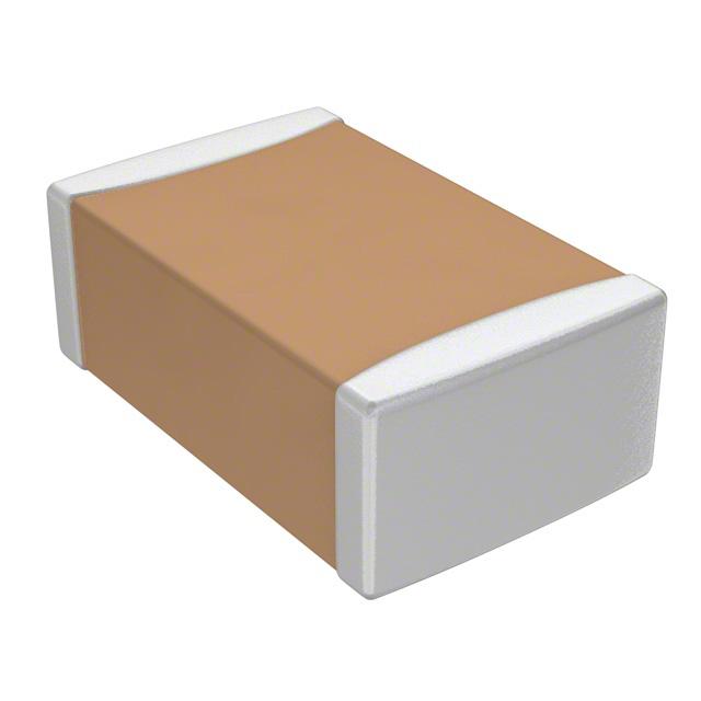


 工商网监
湘ICP备2023018690号
工商网监
湘ICP备2023018690号
