Ordering number : ENA1384A
LC87F2J32A
CMOS IC
FROM 32K byte, RAM 1024 byte on-chip
8-bit 1-chip Microcontroller
Overview
The SANYO LC87F2J32A is an 8-bit microcomputer that, centered around a CPU running at a minimum bus cycle time
of 83.3ns, integrates on a single chip a number of hardware features such as 32K-byte flash ROM (On-boardprogrammable), 1024-byte RAM, an On-chip-debugger, sophisticated 16-bit timers/counters (may be divided into 8-bit
timers), a 16-bit timer/counter (may be divided into 8-bit timers/counters or 8-bit PWMs), four 8-bit timers with
a prescaler, a base timer serving as a time-of-day clock, a high-speed clock counter, a synchronous SIO interface,
an asynchronous/synchronous SIO interface, a UART interface (full duplex), two 12-bit PWM channels, a 12/8-bit
14-channel AD converter, a system clock frequency divider, remote control receive, an internal reset and a 24-source
10-vector interrupt feature.
Features
Flash ROM
• Capable of on-board-programming with wide range (2.2 to 5.5V) of voltage source.
• Block-erasable in 128-byte units
• Writable in 2-byte units
• 32768 × 8 bits
RAM
• 1024 × 9 bits
Minimum Bus Cycle
• 83.3ns (12MHz)
VDD=2.7 to 5.5V
• 100ns (10MHz)
VDD=2.2 to 5.5V
• 250ns (4MHz)
VDD=1.8 to 5.5V
Note: The bus cycle time here refers to the ROM read speed.
* This product is licensed from Silicon Storage Technology, Inc. (USA), and manufactured and sold by
SANYO Semiconductor Co., Ltd.
Any and all SANYO Semiconductor Co.,Ltd. products described or contained herein are, with regard to
"standard application", intended for the use as general electronics equipment (home appliances, AV equipment,
communication device, office equipment, industrial equipment etc.). The products mentioned herein shall not be
intended for use for any "special application" (medical equipment whose purpose is to sustain life, aerospace
instrument, nuclear control device, burning appliances, transportation machine, traffic signal system, safety
equipment etc.) that shall require extremely high level of reliability and can directly threaten human lives in case
of failure or malfunction of the product or may cause harm to human bodies, nor shall they grant any guarantee
thereof. If you should intend to use our products for applications outside the standard applications of our
customer who is considering such use and/or outside the scope of our intended standard applications, please
consult with us prior to the intended use. If there is no consultation or inquiry before the intended use, our
customer shall be solely responsible for the use.
Specifications of any and all SANYO Semiconductor Co.,Ltd. products described or contained herein stipulate
the performance, characteristics, and functions of the described products in the independent state, and are not
guarantees of the performance, characteristics, and functions of the described products as mounted in the
customer' s products or equipment. To verify symptoms and states that cannot be evaluated in an independent
device, the customer should always evaluate and test devices mounted in the customer' s products or
equipment.
Ver.1.20
42209HKIM 20090406-S00001 No.A1384-1/30
�LC87F2J32A
Minimum Instruction Cycle Time
• 250ns (12MHz)
VDD=2.7 to 5.5V
• 300ns (10MHz)
VDD=2.2 to 5.5V
• 750ns (4MHz)
VDD=1.8 to 5.5V
Ports
• Normal withstand voltage I/O ports
Ports I/O direction can be designated in 1-bit units
• Dedicated oscillator ports/input ports
• Reset pin
• Power pins
39 (P0n, P1n, P2n, P30 to P36, P70 to P73, PWM0,
PWM1, XT2, CF2)
2 (CF1, XT1)
1 (RES)
6 (VSS1 to 3, VDD1 to 3)
Timers
• Timer 0: 16-bit timer/counter with a capture register.
Mode 0: 8-bit timer with an 8-bit programmable prescaler (with an 8-bit capture register) × 2 channels
Mode 1: 8-bit timer with an 8-bit programmable prescaler (with an 8-bit capture register)
+ 8-bit counter (with an 8-bit capture register)
Mode 2: 16-bit timer with an 8-bit programmable prescaler (with a 16-bit capture register)
Mode 3: 16-bit counter (with a 16-bit capture register)
• Timer 1: 16-bit timer/counter that supports PWM/toggle outputs
Mode 0: 8-bit timer with an 8-bit prescaler (with toggle outputs)
+ 8-bit timer/counter with an 8-bit prescaler (with toggle outputs)
Mode 1: 8-bit PWM with an 8-bit prescaler × 2 channels
Mode 2: 16-bit timer/counter with an 8-bit prescaler (with toggle outputs)
(toggle outputs also possible from the lower-order 8 bits)
Mode 3: 16-bit timer with an 8-bit prescaler (with toggle outputs)
(The lower-order 8 bits can be used as PWM.)
• Timer 4: 8-bit timer with a 6-bit prescaler
• Timer 5: 8-bit timer with a 6-bit prescaler
• Timer 6: 8-bit timer with a 6-bit prescaler (with toggle output)
• Timer 7: 8-bit timer with a 6-bit prescaler (with toggle output)
• Base timer
1) The clock is selectable from the subclock (32.768kHz crystal oscillation), system clock, and timer 0 prescaler
output.
2) Interrupts are programmable in 5 different time schemes
High-speed Clock Counter
1) Can count clocks with a maximum clock rate of 20MHz (at a main clock of 10MHz)
2) Can generate output real-time
SIO
• SIO0: 8-bit synchronous serial interface
1) LSB first/MSB first mode selectable
2) Built-in 8-bit baudrate generator (maximum transfer clock cycle=4/3 tCYC)
3) Automatic continuous data transmission (1 to 256 bits, specifiable in 1-bit units, suspension and resumption of
data transmission possible in 1-byte units)
• SIO1: 8-bit asynchronous/synchronous serial interface
Mode 0: Synchronous 8-bit serial I/O (2- or 3-wire configuration, 2 to 512 tCYC transfer clocks)
Mode 1: Asynchronous serial I/O (half-duplex, 8-data bits, 1-stop bit, 8 to 2048 tCYC baudrates)
Mode 2: Bus mode 1 (start bit, 8-data bits, 2 to 512 tCYC transfer clocks)
Mode 3: Bus mode 2 (start detect, 8-data bits, stop detect)
UART
• Full duplex
• 7/8/9 bit data bits selectable
• 1 stop bit (2-bit in continuous data transmission)
• Built-in baudrate generator
No.A1384-2/30
�LC87F2J32A
AD Converter: 12 bits/8 bits × 14 channels
• 12/8 bits AD converter resolution selectable
PWM: Multifrequency 12-bit PWM × 2 channels
Remote Control Receiver Circuit (sharing pins with P73, INT3, and T0IN)
1) Noise rejection function
(Units of noise rejection filter : about 120μs, when selecting a 32.768kHz crystal oscillator as a clock.)
2) Supporting reception formats with a guide-pulse of halt-clock/clock/none.
3) Determines a end of reception by detecting a no-signal periods (No carrier).
(Supports same reception format with a different bit length.)
4) X’tal HOLD mode release function
Clock Output Function
• Can generate clock outputs with a frequency of 1/1, 1/2, 1/4, 1/8, 1/16, 1/32, 1/64 of the source clock selected as
the system clock.
• Can generate the source clock for the subclock.
Watchdog timer
• External RC watchdog timer
• Interrupt and reset signals selectable
Interrupts
• 24 sources, 10 vector addresses
1) Provides three levels (low (L), high (H), and highest (X)) of multiplex interrupt control. Any interrupt requests of
the level equal to or lower than the current interrupt are not accepted.
2) When interrupt requests to two or more vector addresses occur at the same time, the interrupt of the highest level
takes precedence over the other interrupts. For interrupts of the same level, the interrupt into the smallest vector
address takes precedence.
No.
Vector Address
Level
1
00003H
X or L
INT0
Interrupt Source
2
0000BH
X or L
INT1
3
00013H
H or L
INT2/T0L/INT4/REMOREC2
4
0001BH
H or L
INT3/INT5/ BT0/BT1
5
00023H
H or L
T0H
6
0002BH
H or L
T1L/T1H
7
00033H
H or L
SIO0/UART1 receive
8
0003BH
H or L
SIO1/UART1 transmit
9
00043H
H or L
ADC/T6/T7
10
0004BH
H or L
Port 0/T4/T5/PWM0, PWM1
• Priority levels X > H > L
• Of interrupts of the same level, the one with the smallest vector address takes precedence.
• IFLG (List of interrupt source flag function)
1) Shows a list of interrupt source flags that caused a branching to a particular vector address (shown in the table
above).
Subroutine Stack Levels: 512 levels (the stack is allocated in RAM)
High-speed Multiplication/Division Instructions
• 16 bits × 8 bits
(5 tCYC execution time)
• 24 bits × 16 bits
(12 tCYC execution time)
• 16 bits ÷ 8 bits
(8 tCYC execution time)
• 24 bits ÷ 16 bits
(12 tCYC execution time)
No.A1384-3/30
�LC87F2J32A
Oscillation Circuits
• Internal oscillation circuits
1) Low-speed RC oscillation circuit :
For system clock(100kHz)
2) Medium-speed RC oscillation circuit :
For system clock(1MHz)
3) Frequency variable RC oscillation circuit:
For system clock(8MHz)
(1) Adjustable in 0.5% (typ) step from a selected center frequency.
(2) Measures oscillation clock using a input signal from XT1 as a reference.
• External oscillation circuits
1) Low speed crystal oscillation circuit:
For low-speed system clock, with internal Rf
2) Hi-speed CF oscillation circuit:
For system clock, with internal Rf
(1) Both the CF and crystal oscillator circuits stop operation on a system reset.
System Clock Divider Function
• Can run on low current.
• The minimum instruction cycle selectable from 300ns, 600ns, 1.2μs, 2.4μs, 4.8μs, 9.6μs, 19.2μs, 38.4μs,
and 76.8μs (at a main clock rate of 10MHz).
Internal Reset Function
• Power-on reset (POR) function
1) POR reset is generated only at power-on time.
2) The POR release level can be selected from 8 levels (1.67V, 1.97V, 2.07V, 2.37V, 2.57V, 2.87V, 3.86V, and
4.35V) through option configuration.
• Low-voltage detection reset (LVD) function
1) LVD and POR functions are combined to generate resets when power is turned on and when power voltage falls
below a certain level.
2) The use/disuse of the LVD function and the low voltage threshold level (7 levels: 1.91V, 2.01V, 2.31V, 2.51V,
2.81V, 3.79V, 4.28V).
Standby Function
• HALT mode: Halts instruction execution while allowing the peripheral circuits to continue operation.
1) Oscillation is not halted automatically.
2) There are three ways of resetting the HALT mode.
(1) Setting the reset pin to the low level
(2) System resetting by watchdog timer or low-voltage detection
(3) Occurrence of an interrupt
• HOLD mode: Suspends instruction execution and the operation of the peripheral circuits.
1) The CF, RC, and crystal oscillators automatically stop operation.
2) There are four ways of resetting the HOLD mode.
(1) Setting the reset pin to the low level.
(2) System resetting by watchdog timer or low-voltage detection
(3) Having an interrupt source established at either INT0, INT1, INT2, INT4, or INT5
* INT0 and INT1 HOLD mode reset is available only when level detection is set.
(4) Having an interrupt source established at port 0
• X'tal HOLD mode: Suspends instruction execution and the operation of the peripheral circuits except the base timer.
1) The CF and RC oscillators automatically stop operation.
2) The state of crystal oscillation established when the X'tal HOLD mode is entered is retained.
3) There are six ways of resetting the X'tal HOLD mode.
(1) Setting the reset pin to the low level
(2) System resetting by watchdog timer or low-voltage detection
(3) Having an interrupt source established at either INT0, INT1, INT2, INT4, or INT5
* INT0 and INT1 HOLD mode reset is available only when level detection is set.
(4) Having an interrupt source established at port 0
(5) Having an interrupt source established in the base timer circuit
(6) Having an interrupt source established in the infrared remote controller receiver circuit
No.A1384-4/30
�LC87F2J32A
On-chip Debugger
• Supports software debugging with the IC mounted on the target board (LC87D2J32A).
LC87F2J32A has an On-chip debugger but its function is limited.
Data Security Function (flash versions only)
• Protects the program data stored in flash memory from unauthorized read or copy.
Note: This data security function does not necessarily provide absolute data security.
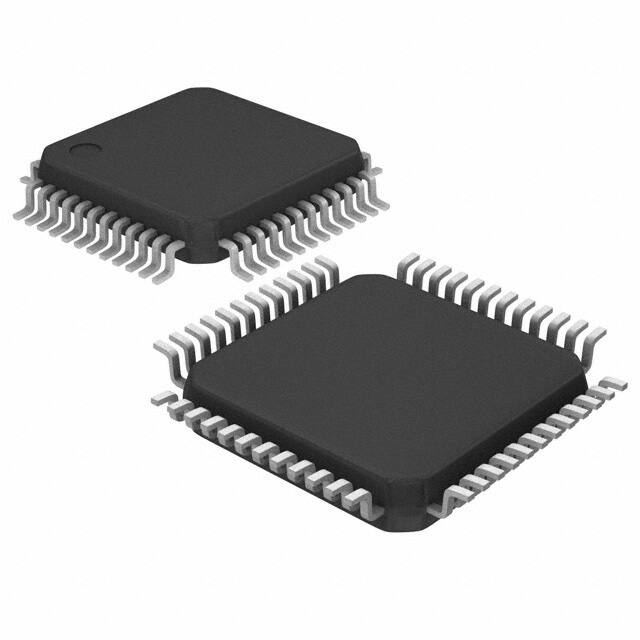
Package Form
• SQFP48 (7×7):
• QIP48E (14×14):
• FLGA49 (5×5):
Lead-/Halogen-free type
Lead-free type
Lead-free type (This package is Built To Order.)
Development Tools
• On-chip debugger: TCB87- TypeB + LC87D2J32A
Programming Board
Package
Programming boards
SQFP48 (7×7)
W87F55256SQ
QIP48E (14×14)
W87F55256Q
Flash ROM Programmer
Maker
Model
Supported version
Device
Rev 03.07 or later
LC87F2J32A
AF9708
Single programmer
AF9709/AF9709B/AF9709C
(Including Ando Electric Co., Ltd. models)
Flash Support Group, Inc.
AF9723/AF9723B(Main body)
(FSG)
Gang programmer
(Including Ando Electric Co., Ltd. models)
AF9833(Unit)
(Including Ando Electric Co., Ltd. models)
Flash Support Group, Inc.
-
AF9101/AF9103(Main body)
(FSG)
+
-
(FSG models)
In-circuit programmer
(Note 2)
Sanyo
SIB87(Inter Face Driver)
(Note 1)
(SANYO model)
Single/Gang programmer
SANYO
SKK/SKK Type B
(SANYO FWS)
In-circuit/
SKK-DBG Type B
Gang programmer
(SANYO FWS)
LC87F2J32A
Application Version
1.04 or later
Chip Data Version
LC87F2J32A
2.16 or later
Note1: On-board-programmer from FSG (AF9101/AF9103) and serial interface driver from SANYO (SIB87) together
can give a PC-less, standalone on-board-programming capabilities.
Note2: It needs a special programming devices and applications depending on the use of programming environment.
Please ask FSG or SANYO for the information.
No.A1384-5/30
�LC87F2J32A
Package Dimensions
unit : mm (typ)
3163B
36
0.5
9.0
7.0
25
24
48
13
7.0
9.0
37
1
12
0.5
0.15
0.18
(1.5)
0.1
1.7max
(0.75)
SANYO : SQFP48(7X7)
Package Dimensions
unit : mm (typ)
3156A
17.2
0.8
14.0
24
48
13
14.0
37
1
17.2
25
36
12
1.0
0.35
0.15
0.1
3.0max
(2.7)
(1.5)
SANYO : QIP48E(14X14)
No.A1384-6/30
�LC87F2J32A
36
35
34
33
32
31
30
29
28
27
26
25
P27/INT5/T1IN
P26/INT5/T1IN
P25/INT5/T1IN
P24/INT5/T1IN
P23/INT4/T1IN
P22/INT4/T1IN
P21/URX/INT4/T1IN
P20/UTX/INT4/T1IN
P07/T7O/AN7
P06/T6O/AN6
P05/CKO/AN5
P04/AN4
Pin Assignment
37
38
39
40
41
42
43
44
45
46
47
48
LC87F2J32A
P03/AN3
P02/AN2
P01/AN1
P00/AN0
VSS2
VDD2
PWM0
PWM1
P17/T1PWMH/BUZ
P16/T1PWML
P15/SCK1
P14/SI1/SB1
24
23
22
21
20
19
18
17
16
15
14
13
P73/INT3/T0IN/RMIN
RES
XT1/AN10
XT2/AN11
VSS1
CF1/AN12
CF2/AN13
VDD1
P10/SO0
P11/SI0/SB0
P12/SCK0
P13/SO1
1
2
3
4
5
6
7
8
9
10
11
12
P36
P35
VDD3
VSS3
P34
P33
P32/DBGP2
P31/DBGP1
P30/DBGP0
P70/INT0/T0LCP/AN8
P71/INT1/T0HCP/AN9
P72/INT2/T0IN
Top view
SANYO: SQFP48 (7×7)
SANYO: QIP48E (14×14)
SQFP/QIP
NAME
SQFP/QIP
NAME
“Lead- / Halogen-free Type”
“Lead-free Type”
SQFP/QIP
NAME
1
P73/INT3/T0IN/RMIN
17
PWM1
33
P24/INT5/T1IN
2
RES
18
PWM0
34
P25/INT5/T1IN
3
XT1/AN10
19
VDD2
35
P26/INT5/T1IN
4
XT2/AN11
20
VSS2
36
P27/INT5/T1IN
5
VSS1
21
P00/AN0
37
P36
6
CF1/AN12
22
P01/AN1
38
P35
7
CF2/AN13
23
P02/AN2
39
VDD3
8
VDD1
24
P03/AN3
40
VSS3
9
P10/SO0
25
P04/AN4
41
P34
10
P11/SI0/SB0
26
P05/CKO/AN5
42
P33
11
P12/SCK0
27
P06/T6O/AN6
43
P32/DBGP2
12
P13/SO1
28
P07/T7O/AN7
44
P31/DBGP1
13
P14/SI1/SB1
29
P20/UTX/INT4/T1IN
45
P30/DBGP0
14
P15/SCK1
30
P21/URX/INT4/T1IN
46
P70/INT0/T0LCP/AN8
15
P16/T1PWML
31
P22/INT4/T1IN
47
P71/INT1/T0HCP/AN9
16
P17/T1PWMH/BUZ
32
P23/INT4/T1IN
48
P72/INT2/T0IN
No.A1384-7/30
�LC87F2J32A
System Block Diagram
Interrupt control
IR
PLA
Flash ROM
Standby control
SRC
RC
Clock
generator
CF/
X'tal
PC
MRC
WDT
Reset circuit
(LVD/POR)
Reset control
RES
ACC
B register
SIO0
Bus interface
SIO1
Port 0
C register
ALU
Timer 0
Port 1
Timer 1
Port 2
PSW
Timer 4
Port 3
RAR
Timer 5
Port 7
RAM
Timer 6
ADC
Stack pointer
Timer 7
UART1
Watchdog timer
Base timer
Remote control
receiver circuit
PWM0
INT0-2, INT4, 5
INT3 (Noise filter)
On-chip debugger
PWM1
No.A1384-8/30
�LC87F2J32A
Pin Description
Pin Name
VSS1 to
I/O
Description
Option
-
- power supply pins
No
-
+ power supply pin
No
• 8-bit I/O port
Yes
VSS3
VDD1 to
VDD3
Port 0
I/O
• I/O specifiable in 1-bit units
P00 to P07
• Pull-up resistors can be turned on and off in 1-bit units.
• HOLD reset input
• Port 0 interrupt input
• Pin functions
P05: System clock output
P06: Timer 6 toggle output
P07: Timer 7 toggle output
P00(AN0) to P07(AN7): AD converter input
Port 1
I/O
• 8-bit I/O port
Yes
• I/O specifiable in 1-bit units
P10 to P17
• Pull-up resistors can be turned on and off in 1-bit units.
• Pin functions
P10: SIO0 data output
P11: SIO0 data input/bus I/O
P12: SIO0 clock I/O
P13: SIO1 data output
P14: SIO1 data input / bus I/O
P15: SIO1 clock I/O
P16: Timer 1PWML output
P17: Timer 1PWMH output/beeper output
Port 2
I/O
Yes
• 8-bit I/O port
• I/O specifiable in 1-bit units
P20 to P27
• Pull-up resistors can be turned on and off in 1-bit units.
• Pin functions
P20: UART transmit
P21: UART receive
P20 to P23: INT4 input/HOLD reset input/timer 1 event input/timer 0L capture input/
timer 0H capture input
P24 to P27: INT5 input/HOLD reset input/timer 1 event input/timer 0L capture input/
timer 0H capture input
Interrupt acknowledge type
Port 3
P30 to P36
I/O
Rising
Falling
INT4
enable
enable
INT5
enable
enable
Rising &
H level
L level
enable
disable
disable
enable
disable
disable
Falling
• 7-bit I/O port
Yes
• I/O specifiable in 1-bit units
• Pull-up resistors can be turned on and off in 1-bit units.
• Shared pins
On-chip debugger pins: DBGP0 to DBGP2 (P30 to P32)
Continued on next page.
No.A1384-9/30
�LC87F2J32A
Continued from preceding page.
Pin Name
I/O
I/O
Port 7
Description
Option
No
• 4-bit I/O port
• I/O specifiable in 1-bit units
P70 to P73
• Pull-up resistors can be turned on and off in 1-bit units.
• Pin functions
P70: INT0 input/HOLD reset input/timer 0L capture input/watchdog timer output
P71: INT1 input/HOLD reset input/timer 0H capture input
P72: INT2 input HOLD reset input/timer 0 event input/timer 0L capture input
P73: INT3 input (with noise filter)/timer 0 event input/timer 0H capture input
P70(AN8), P71(AN9) : AD converter input
Interrupt acknowledge type
PWM0, PWM1
I/O
Rising
Falling
INT0
enable
enable
INT1
enable
enable
INT2
enable
INT3
enable
Rising &
H level
L level
disable
enable
enable
disable
enable
enable
enable
enable
disable
disable
enable
enable
disable
disable
Falling
• PWM0 and PWM1 output ports
No
• General-purpose I/O available
RES
I/O
XT1
Input
External reset Input/internal reset output
No
• 32.768kHz crystal oscillator input pin
No
• Shared pins
General-purpose input port
AD converter input port: AN10
XT2
I/O
• 32.768kHz crystal oscillator output pin
No
• Shared pins
General-purpose I/O port
AD converter input port: AN11
CF1
Input
Ceramic resonator input pin
No
• Shared pins
General-purpose input port
AD converter input port: AN12
CF2
Output
Ceramic resonator output pin
No
• Shared pins
General-purpose I/O port
AD converter input port: AN13
On-chip Debugger Pin Connection Requirements
For the treatment of the on-chip debugger pins, refer to the separately available documents entitled “RD87 On-chip
Debugger Installation Manual”
Recommended Unused Pin Connections
Recommended Unused Pin Connections
Port Name
Board
Software
P00 to P07
Open
Output low
P10 to P17
Open
Output low
P20 to P21
Open
Output low
P30 to P36
Open
Output low
P70 to P73
Open
Output low
PWM0,PWM1
Open
Output low
XT1
Pulled low with a 100kΩ resistor or less
General-purpose input port
XT2
Open
Output low
CF1
Pulled low with a 100kΩ resistor or less
General-purpose input port
CF2
Open
Output low
No.A1384-10/30
�LC87F2J32A
Port Output Types
The table below lists the types of port outputs and the presence/absence of a pull-up resistor.
Data can be read into any input port even if it is in the output mode.
Port Name
Option Selected
in Units of
P00 to P07
1 bit
P10 to P17
1 bit
P20 to P27
P30 to P36
1 bit
1 bit
Option Type
Output Type
Pull-up Resistor
1
CMOS
Programmable (Note 1)
2
Nch-open drain
Programmable (Note 1)
1
CMOS
Programmable
2
Nch-open drain
Programmable
1
CMOS
Programmable
2
Nch-open drain
Programmable
1
CMOS
Programmable
2
Nch-open drain
Programmable
P70
-
No
Nch-open drain
Programmable
P71 to P73
-
No
CMOS
Programmable
PWM0, PWM1
-
No
CMOS
No
XT1
-
No
Input for 32.768kHz crystal oscillator
No
(Input only)
XT2
-
No
Output for 32.768kHz crystal oscillator
No
(Nch-open drain when in general-purpose
output mode)
CF1
-
No
Input for ceramic resonator oscillator
No
(Input only)
CF2
-
No
Output for ceramic resonator oscillator
No
(Nch-open drain when in general-purpose
output mode)
Note 1: The control of the presence or absence of the programmable pull-up resistors for port 0 and the switching
between low- and high-impedance pull-up connection is exercised in 1-bit units.
No.A1384-11/30
�LC87F2J32A
User Option Table
Option name
Option to be applied on
Port output type
P00 to P07
P10 to P17
function
Power-on reset
function
{
1 bit
Nch-open drain
CMOS
{
1 bit
Nch-open drain
CMOS
1 bit
P30 to P36
{
1 bit
Nch-open drain
CMOS
Nch-open drain
00000h
-
{
-
Detect function
{
-
Detect level
{
-
Power-On reset level
Option selection
CMOS
{
Low-voltage
detection reset
Option selected in units of
P20 to P27
Program start
address
Flash-ROM version
07E00h
Enable: Use
{
-
Disable: Not Used
7-level
8-level
Note: To reduce VDD signal noise and to increase the duration of the backup battery supply, VSS1, VSS2, and VSS3
should connect to each other and they should also be grounded.
Example 1: During backup in hold mode, port output ‘H’ level is supplied from the back-up capacitor.
LSI
Back-up capacitor
Power
Supply
VDD1
VDD2
VDD3
VSS1 VSS2 VSS3
Example 2: During backup in hold mode, output is not held high and its value in unsettled.
LSI
Back-up capacitor
Power
Supply
VDD1
VDD2
VDD3
VSS1 VSS2 VSS3
No.A1384-12/30
�LC87F2J32A
Absolute Maximum Ratings at Ta = 25°C, VSS1 = VSS2 = VSS3 = 0V
Parameter
Symbol
Pin/Remarks
Specification
Conditions
VDD[V]
Maximum supply
VDD max
VDD1, VDD2, VDD3
Input voltage
VI
XT1, CF1
Input/output
VIO
Ports 0, 1, 2, 3,
VDD1=VDD2=VDD3
voltage
voltage
Port 7, PWM0,
min
typ
max
unit
-0.3
+6.5
-0.3
VDD+0.3
-0.3
VDD+0.3
V
PWM1, XT2, CF2
Peak output
IOPH(1)
Ports 0, 1, 2, 3
current
High level output current
Mean output
Per 1 applicable pin
IOPH(2)
PWM0, PWM1
IOPH(3)
P71 to P73
Per 1 applicable pin
IOMH(1)
Ports 0, 1, 2, 3
CMOS output select
current
(Note 1-1)
CMOS output select
-10
-20
Per 1 applicable pin
-5
-7.5
IOMH(2)
PWM0, PWM1
IOMH(3)
P71 to P73
Per 1 applicable pin
Total output
ΣIOAH(1)
P71 to P73
Total of all applicable pins
-10
current
ΣIOAH(2)
Port 0
Total of all applicable pins
-25
ΣIOAH(3)
Port 1,
Total of all applicable pins
-15
PWM0, PWM1
ΣIOAH(4)
Ports 0, 1,
Total of all applicable pins
PWM0, PWM1
Peak output
-3
-25
-45
ΣIOAH(5)
Ports 2, P35, P36
Total of all applicable pins
-25
ΣIOAH(6)
P30 to P34
Total of all applicable pins
-25
ΣIOAH(7)
Pots 2, 3
Total of all applicable pins
-45
IOPL(1)
P02 to P07,
Per 1 applicable pin
current
20
Ports 1, 2, 3,
mA
PWM0, PWM1
Low level output current
Mean output
IOPL(2)
P00, P01
Per 1 applicable pin
30
IOPL(3)
Port 7, XT2, CF2
Per 1 applicable pin
10
IOML(1)
P02 to P07,
Per 1 applicable pin
current
Ports 1, 2, 3,
(Note 1-1)
PWM0, PWM1
15
IOML(2)
P00, P01
Per 1 applicable pin
20
IOML(3)
Port 7, XT2, CF2
Per 1 applicable pin
7.5
Total output
ΣIOAL(1)
Port 7, XT2, CF2
Total of all applicable pins
15
current
ΣIOAL(2)
Port 0
Total of all applicable pins
45
ΣIOAL(3)
Port 1,
Total of all applicable pins
45
PWM0, PWM1
ΣIOAL(4)
Port 0, 1,
Total of all applicable pins
80
PWM0, PWM1
Power dissipation
ΣIOAL(5)
Ports 2, P35, P36
Total of all applicable pins
45
ΣIOAL(6)
P30 to P34
Total of all applicable pins
45
ΣIOAL(7)
Ports 2, 3
Total of all applicable pins
60
Pd max(1)
SQFP48 (7×7)
Ta=-40 to +85°C
139
Package only
Pd max(2)
Ta=-40 to +85°C
356
Package with thermal
resistance board (Note 1-2)
Pd max(3)
QIP48E (14×14)
mW
Ta=-40 to +85°C
281
Package only
Pd max(4)
Ta=-40 to +85°C
Package with thermal
489
resistance board (Note 1-2)
Operating ambient
Topr
temperature
Storage ambient
temperature
Tstg
-40
+85
-55
+125
°C
Note 1-1: The mean output current is a mean value measured over 100ms.
Note 1-2: SEMI standards thermal resistance board (size: 76.1×114.3×1.6tmm, glass epoxy) is used.
No.A1384-13/30
�LC87F2J32A
Allowable Operating Conditions at Ta = -40°C to +85°C, VSS1 = VSS2 = VSS3 = 0V
Parameter
Symbol
Pin/Remarks
Specification
Conditions
VDD[V]
max
unit
VDD(1)
supply voltage
VDD(2)
0.294μs≤tCYC≤200μs
2.2
5.5
VDD(3)
0.735μs≤tCYC≤200μs
1.8
5.5
1.6
5.5
Memory
VHD
VDD1=VDD2=VDD3
sustaining
0.245μs≤tCYC≤200μs
typ
Operating
(Note 2-1)
VDD1=VDD2=VDD3
min
2.7
5.5
RAM and register contents
sustained in HOLD mode.
supply voltage
High level
VIH(1)
input voltage
Ports 1, 2, 3,
P71 to P73
P70 port input/
1.8 to 5.5
interrupt side
0.3VDD
VDD
+0.7
PWM0, PWM1
VIH(2)
VIH(3)
Port 0
1.8 to 5.5
Port 70 watchdog
timer side
VIH(4)
Low level
VIL(1)
input voltage
XT1, XT2, CF1, CF2,
RES
Ports 1, 2, 3,
P71 to P73
0.3VDD
VDD
+0.7
1.8 to 5.5
0.9VDD
VDD
1.8 to 5.5
0.75VDD
VDD
4.0 to 5.5
VSS
1.8 to 4.0
VSS
4.0 to 5.5
VSS
1.8 to 4.0
VSS
1.8 to 5.5
VSS
1.8 to 5.5
VSS
0.25VDD
V
0.1VDD
+0.4
P70 port input/
interrupt side
0.2VDD
PWM0, PWM1
VIL(2)
VIL(3)
Port 0
Port 70 watchdog
timer side
VIL(4)
XT1, XT2, CF1, CF2,
RES
0.15VDD
+0.4
0.2VDD
0.8VDD
-1.0
Instruction
tCYC
2.7 to 5.5
0.245
200
cycle time
(Note 2-2)
2.2 to 5.5
0.294
200
(Note 2-1)
External
FEXCF
CF1
system clock
• CF2 pin open
1.8 to 5.5
0.735
200
2.7 to 5.5
0.1
12
1.8 to 5.5
0.1
4
3.0 to 5.5
0.2
24.4
2.0 to 5.5
0.2
8
μs
• System clock frequency division
frequency
ratio=1/1
• External system clock duty=
50±5%
• CF2 pin open
MHz
• System clock frequency division
ratio=1/2
• External system clock duty=
50±5%
Oscillation
FmCF(1)
CF1, CF2
frequency
range
12MHz ceramic oscillation
See Fig. 1.
FmCF(2)
CF1, CF2
(Note 2-3)
10MHz ceramic oscillation
See Fig. 1.
FmCF(3)
CF1, CF2
2.7 to 5.5
12
2.2 to 5.5
10
1.8 to 5.5
4
2.2 to 5.5
4
4MHz ceramic oscillation.
CF oscillation normal amplifier size
selected.
MHz
See Fig. 1. CFLAMP=0)
4MHz ceramic oscillation.
CF oscillation low amplifier size
selected. (CFLAMP=1)
See Fig. 1.
Note 2-1: VDD must be held greater than or equal to 2.2V in the flash ROM onboard programming mode.
Note 2-2: Relationship between tCYC and oscillation frequency is 3/FmCF at a division ratio of 1/1 and 6/FmCF at
a division ratio of 1/2.
Continued on next page.
No.A1384-14/30
�LC87F2J32A
Continued from preceding page.
Parameter
Symbol
Pin/Remarks
Specification
Conditions
VDD[V]
Oscillation
FmMRC(1)
frequency
1/2 frequency division ratio.
range
(RCCTD=0)
(Note 2-3)
FmMRC(2)
Ta=-10 to +50°C
FmRC
unit
2.4 to 5.5
7.44
8.0
8.56
2.4 to 5.5
7.6
8.0
8.4
1.8 to 5.5
0.5
1.0
2.0
FmSRC
Internal Low-speed RC oscillation
XT1, XT2
1.8 to 5.5
50
100
200
MHz
(Note 2-4)
Internal Medium-speed RC
oscillation
32.768kHz crystal oscillation
See Fig. 3.
OpVMRC
max
Frequency variable RC oscillation.
(RCCTD=0)
Frequency
typ
(Note 2-4)
1/2 frequency division ratio.
FsX’tal
min
Frequency variable RC oscillation.
kHz
32.768
1.8 to 5.5
Frequency variable RC oscillation.
variable RC
1/2 frequency division ratio.
oscillation
(RCCTD=0)
2.4 to 5.5
6
8
10
2.4 to 5.5
3.6
7.0
11
2.4 to 5.5
0.7
1.5
2.3
2.4 to 5.5
0.2
0.5
1.1
MHz
usable range
Frequency
VmADJ(1)
Each step of VMRCHBn
VmADJ(2)
Each step of VMFCHBn
VmADJ(3)
Each step of VMDCHn
variable RC
oscillation
adjustment
range
%
Note 2-3: See Tables 1 and 2 for the oscillation constants.
Note 2-4: When switching the system clock, allow an oscillation stabilization time of 100μs or longer after the
multifrequency RC oscillator circuit transmits from the "oscillation stopped" to "oscillation enabled" state.
No.A1384-15/30
�LC87F2J32A
Electrical Characteristics at Ta = -40°C to +85°C, VSS1 = VSS2 = VSS3 = 0V
Parameter
Symbol
Pin/Remarks
Specification
Conditions
VDD[V]
High level input
IIH(1)
current
Ports 0, 1, 2, 3
Output disabled
Ports 7
RES
Pull-up resistor off
PWM0, PWM1
(Including output Tr's off leakage
VIN=VDD
min
typ
max
unit
1.8 to 5.5
1
1.8 to 5.5
1
1.8 to 5.5
15
current)
IIH(2)
XT1, XT2, CF2
Input port selected
VIN=VDD
Low level input
IIH(3)
CF1
VIN=VDD
IIL(1)
Ports 0, 1, 2, 3
Output disabled
Port 7
RES
Pull-up resistor off
PWM0, PWM1
(Including output Tr's off leakage
current
VIN=VSS
1.8 to 5.5
-1
1.8 to 5.5
-1
μA
current)
IIL(2)
XT1, XT2, CF2
Input port selected
VIN=VSS
IIL(3)
CF1
VIN=VSS
1.8 to 5.5
-15
High level
VOH(1)
Ports 0, 1, 2, 3,
IOH=-1mA
4.5 to 5.5
output voltage
VOH(2)
P71 to P73
IOH=-0.35mA
VDD-1
VDD
VOH(3)
IOH=-0.15mA
VOH(4)
PWM0, PWM1,
IOH=-6mA
VOH(5)
P05(System clock
IOH=-1.4mA
output function
2.7 to 5.5
1.8 to 5.5
4.5 to 5.5
2.7 to 5.5
-0.4
VDD
-0.4
VDD-1
VDD
-0.4
VOH(6)
used)
Low level
VOL(1)
Ports 0, 1, 2, 3,
IOL=10mA
4.5 to 5.5
1.5
output voltage
VOL(2)
PWM0, PWM1,
IOL=1.4mA
2.7 to 5.5
0.4
IOL=0.8mA
1.8 to 5.5
0.4
P00, P01
IOL=25mA
4.5 to 5.5
1.5
VOL(5)
IOL=4mA
2.7 to 5.5
0.4
VOL(6)
IOL=2mA
1.8 to 5.5
0.4
Port 7, XT2, CF2
IOL=1.4mA
2.7 to 5.5
0.4
0.4
VOL(3)
VOL(4)
VOL(7)
VOL(8)
IOH=-0.8mA
1.8 to 5.5
VDD
-0.4
V
IOL=0.8mA
1.8 to 5.5
Pull-up
Rpu(1)
Ports 0, 1, 2, 3
VOH=0.9VDD
4.5 to 5.5
15
35
80
resistance
Rpu(2)
Port 7
When Port 0 selected
1.8 to 4.5
18
50
230
low-impedance pull-up.
Rpu(3)
Port 0
VOH=0.9VDD
When Port 0 selected
kΩ
1.8 to 5.5
100
210
400
High-impedance pull-up.
Hysteresis
VHYS(1)
voltage
Ports 1, 2, 3, 7,
RES, XT2
2.7 to 5.5
VHYS(2)
Pin
capacitance
CP
1.8 to 2.7
All pins
For pins other than that under test:
VIN=VSS, f=1MHz, Ta=25°C
1.8 to 5.5
0.1
VDD
V
0.07
VDD
10
pF
No.A1384-16/30
�LC87F2J32A
Serial Input/Output Characteristics at Ta = -40°C to +85°C, VSS1 = VSS2 = VSS3 = 0V
1. SIO0 Serial I/O Characteristics (Note 4-1-1)
Parameter
Symbol
Pin/Remarks
Specification
Conditions
Input clock
Frequency
tSCK(1)
Low level
tSCKL(1)
SCK0(P12)
• See Fig. 6.
typ
Serial input
unit
1
tSCKH(1)
tCYC
1
Frequency
tSCK(2)
Low level
tSCKL(2)
SCK0(P12)
• CMOS output selected
1/2
1.8 to 5.5
pulse width
High level
4/3
• See Fig. 6
tSCK
tSCKH(2)
1/2
pulse width
Data setup time
tsDI(1)
SB0(P11),
SI0(P11)
Data hold time
• Must be specified with
SIOCLK.
thDI(1)
0.05
respect to rising edge of
1.8 to 5.5
• See Fig. 6.
Input clock
Output delay
tdD0(1)
time
SO0(P10),
SB0(P11)
0.05
• Continuous data
(1/3)tCYC
transmission/reception mode
+0.08
(Note 4-1-2)
tdD0(2)
• Synchronous 8-bit mode
tdD0(3)
(Note 4-1-2)
(Note 4-1-2)
μs
1tCYC
+0.08
1.8 to 5.5
Output clock
Serial output
max
2
1.8 to 5.5
pulse width
High level
min
pulse width
Output clock
Serial clock
VDD[V]
(1/3)tCYC
+0.08
Note 4-1-1: These specifications are theoretical values. Add margin depending on its use.
Note 4-1-2: Must be specified with respect to falling edge of SIOCLK. Must be specified as the time to the beginning
of output state change in open drain output mode. See Fig. 6.
2. SIO1 Serial I/O Characteristics (Note 4-2-1)
Parameter
Symbol
Pin/Remarks
Specification
Conditions
Input clock
Frequency
tSCK(3)
Low level
tSCKL(3)
SCK1(P15)
• See Fig. 6.
tSCK(4)
Low level
tSCKL(4)
1
SCK1(P15)
• CMOS output selected
2
• See Fig. 6.
1/2
1.8 to 5.5
tSCK
tSCKH(4)
1/2
Serial input
pulse width
Data setup time
tsDI(2)
SB1(P14),
SI1(P14)
Data hold time
0.05
respect to rising edge of
SIOCLK.
thDI(2)
tdD0(4)
SO1(P13),
SB1(P14)
Serial output
• Must be specified with
1.8 to 5.5
• See Fig. 6.
Output delay time
unit
1
pulse width
High level
max
tCYC
tSCKH(3)
Frequency
typ
2
1.8 to 5.5
pulse width
High level
min
pulse width
Output clock
Serial clock
VDD[V]
0.05
• Must be specified with
μs
respect to falling edge of
SIOCLK.
• Must be specified as the
time to the beginning of
1.8 to 5.5
(1/3)tCYC
+0.08
output state change in
open drain output mode.
• See Fig. 6.
Note 4-2-1: These specifications are theoretical values. Add margin depending on its use.
No.A1384-17/30
�LC87F2J32A
Pulse Input Conditions at Ta = -40°C to +85°C, VSS1 = VSS2 = VSS3 = 0V
Parameter
Symbol
Pin/Remarks
Specification
Conditions
VDD[V]
High/low level
tPIH(1)
INT0(P70),
• Interrupt source flag can be set.
pulse width
tPIL(1)
INT1(P71),
• Event inputs for timer 0 or 1 are
INT2(P72),
enabled.
min
typ
1.8 to 5.5
1
1.8 to 5.5
2
1.8 to 5.5
64
max
unit
INT4(P20 to P23)
INT5(P24 to P27)
tPIH(2)
INT3(P73) when
• Interrupt source flag can be set.
tPIL(2)
noise filter time
• Event inputs for timer 0 are enabled.
tCYC
constant is 1/1
tPIH(3)
INT3(P73) when
• Interrupt source flag can be set.
tPIL(3)
noise filter time
• Event inputs for timer 0 are enabled.
constant is 1/32
tPIH(4)
INT3(P73) when
• Interrupt source flag can be set.
tPIL(4)
noise filter time
• Event inputs for timer 0 are enabled.
1.8 to 5.5
256
• Resetting is enabled.
1.8 to 5.5
200
constant is 1/128
tPIL(5)
RES
μs
AD Converter Characteristics at VSS1 = VSS2 = VSS3 = 0V
Parameter
Symbol
Pin/Remarks
Specification
Conditions
VDD[V]
Resolution
N
AN0(P00) to
Absolute
ET
AN7(P07)
AN8(P70)
accuracy
2.4 to 5.5
TCAD
time
Analog input
AN10(XT1)
AN11(XT2)
max
unit
12
bit
3.0 to 5.5
±16
(Note 6-1)
2.4 to 3.6
±20
• See Conversion time calculation
4.0 to 5.5
32
115
formulas. (Note 6-2)
3.0 to 5.5
64
115
2.4 to 3.6
410
425
2.4 to 5.5
VSS
VDD
AN12(CF1)
• See Conversion time calculation
AN13(CF2)
formulas. (Note 6-2)
VAIN
voltage range
Analog port
IAINH(1)
analog channel
VAIN=VDD
2.4 to 5.5
input current
IAINL(1)
except AN12
VAIN=VSS
2.4 to 5.5
IAINH(2)
AN12
VAIN=VDD
2.4 to 5.5
VAIN=VSS
2.4 to 5.5
IAINL(2)
typ
(Note 6-1)
AN9(P71)
Conversion
min
LSB
μs
V
1
-1
15
μA
-15
Note 6-1: The quantization error (±1/2LSB) must be excluded from the absolute accuracy. The absolute accuracy must
be measured in the microcontroller's state in which no I/O operations occur at the pins adjacent to the analog
input channel.
Note 6-2: The conversion time refers to the period from the time an instruction for starting a conversion process till the
time the conversion results register(s) are loaded with a complete digital conversion value corresponding to
the analog input value.
The conversion time is 2 times the normal-time conversion time when:
• The first AD conversion is performed in the 12-bit AD conversion mode after a system reset.
• The first AD conversion is performed after the AD conversion mode is switched from 8-bit to 12-bit
conversion mode.
No.A1384-18/30
�LC87F2J32A
Parameter
Symbol
Pin/Remarks
Specification
Conditions
VDD[V]
Resolution
N
AN0(P00) to
Absolute
ET
AN7(P07)
accuracy
AN8(P70)
Conversion
AN9(P71)
TCAD
(Note 6-1)
• See Conversion time calculation
formulas. (Note 6-2)
• See Conversion time calculation
AN12(CF1)
formulas. (Note 6-2)
AN13(CF2)
VAIN
voltage range
unit
bit
±1.5
4.0 to 5.5
20
90
3.0 to 5.5
40
90
2.4 to 3.6
250
265
2.4 to 5.5
VSS
VDD
Analog port
IAINH(1)
analog channel
VAIN=VDD
2.4 to 5.5
input current
IAINL(1)
except AN12
VAIN=VSS
2.4 to 5.5
IAINH(2)
AN12
VAIN=VDD
2.4 to 5.5
VAIN=VSS
2.4 to 5.5
IAINL(2)
max
8
2.4 to 5.5
AN11(XT2)
Analog input
typ
2.4 to 5.5
AN10(XT1)
time
min
LSB
μs
V
1
-1
15
μA
-15
Conversion time calculation formulas:
12bits AD Converter Mode: TCAD(Conversion time)= ((52/(AD division ratio))+2)×(1/3)×tCYC
8bits AD Converter Mode: TCAD(Conversion time)=((32/(AD division ratio))+2)×(1/3)×tCYC
External
Operating supply
oscillation
voltage range
(FmCF)
(VDD)
CF-12MHz
CF-10MHz
CF-4MHz
System division ratio
Cycle time
(SYSDIV)
(tCYC)
4.0V to 5.5V
1/1
3.0V to 5.5V
1/1
AD conversion time
AD division
(TCAD)
ratio
(ADDIV)
12bit AD
8bit AD
250ns
1/8
34.8μs
21.5μs
250ns
1/16
69.5μs
42.8μs
4.0V to 5.5V
1/1
300ns
1/8
41.8μs
25.8μs
3.0V to 5.5V
1/1
300ns
1/16
83.4μs
51.4μs
3.0V to 5.5V
1/1
750ns
1/8
104.5μs
64.5μs
2.4V to 3.6V
1/1
750ns
1/32
416.5μs
256.5μs
Note 6-1: The quantization error (±1/2LSB) must be excluded from the absolute accuracy. The absolute accuracy must
be measured in the microcontroller's state in which no I/O operations occur at the pins adjacent to the analog
input channel.
Note 6-2: The conversion time refers to the period from the time an instruction for starting a conversion process till the
time the conversion results register(s) are loaded with a complete digital conversion value corresponding to
the analog input value.
The conversion time is 2 times the normal-time conversion time when:
• The first AD conversion is performed in the 12-bit AD conversion mode after a system reset.
• The first AD conversion is performed after the AD conversion mode is switched from 8-bit to 12-bit
conversion mode.
Power-on reset (POR) Characteristics at Ta = -40 to +85°C, VSS1 = VSS2 = VSS3 = 0V
Specification
Parameter
Symbol
Pin/Remarks
Conditions
Option selected
voltage
POR release
PORRL
voltage
Detection voltage
(Note 7-1)
POUKS
unknown state
Power supply rise
time
• Select from option.
• See Fig. 8.
(Note 7-2)
PORIS
min
typ
max
1.67V
1.55
1.67
1.79
1.97V
1.85
1.97
2.09
2.07V
1.95
2.07
2.19
2.37V
2.25
2.37
2.49
2.57V
2.45
2.57
2.69
2.87V
2.75
2.87
2.99
3.86V
3.73
3.86
3.99
4.35V
4.21
4.35
4.49
0.7
0.95
• Power supply rise
100
time from 0V to 1.6V.
unit
V
ms
Note7-1: The POR release level can be selected out of 8 levels only when the LVD reset function is disabled.
Note7-2: POR is in an unknown state before transistors start operation.
No.A1384-19/30
�LC87F2J32A
Low voltage detection reset (LVD) Characteristics at Ta = -40 to +85°C, VSS1=VSS2=VSS3=0V
Specification
Parameter
Symbol
Pin/Remarks
Conditions
Option selected
voltage
LVD reset
LVDET
• Select from option.
Voltage
(Note 8-1)
(Note 8-2)
(Note 8-3)
• See Fig. 9.
LVD hysteresis
LVHYS
width
Detection voltage
LVUKS
unknown state
Low voltage
detection
minimum width
min
max
1.91V
1.81
1.91
2.01
2.01V
1.91
2.01
2.11
2.31V
2.21
2.31
2.41
2.51V
2.41
2.51
2.61
2.81V
2.71
2.81
2.91
3.79V
3.69
3.79
3.89
4.28V
4.18
4.28
4.38
1.91V
55
2.01V
55
2.31V
55
2.51V
55
2.81V
60
3.79V
65
4.28V
65
• See Fig. 9.
0.7
(Note 8-4)
TLVDW
typ
unit
V
mV
0.95
V
• LVDET-0.5V
• See Fig. 10.
0.2
ms
(Reply sensitivity)
Note8-1: The LVD reset level can be selected out of 7 levels only when the LVD reset function is enabled.
Note8-2: LVD reset voltage specification values do not include hysteresis voltage.
Note8-3: LVD reset voltage may exceed its specification values when port output state changes and/or when a large
current flows through port.
Note8-4: LVD is in an unknown state before transistors start operation.
No.A1384-20/30
�LC87F2J32A
Consumption Current Characteristics at Ta = -40°C to +85°C, VSS1 = VSS2 = VSS3 = 0V
Parameter
Normal mode
Symbol
IDDOP(1)
consumption
current
(Note 9-1)
Pin/
Specification
Conditions
Remarks
VDD[V]
VDD1
• FmCF=12MHz ceramic oscillation mode
=VDD2
=VDD3
• System clock set to 12MHz side
min
typ
max
2.7 to 5.5
6.6
11.3
2.7 to 3.6
4.0
7.3
3.0 to 5.5
8.0
12.7
3.0 to 3.6
4.6
7.6
2.2 to 5.5
5.9
10.5
2.2 to 3.6
3.6
6.7
1.8 to 5.5
2.6
6.1
1.8 to 3.6
1.9
3.9
2.2 to 5.5
0.9
2.2
2.2 to 3.6
0.5
1.1
1.8 to 5.5
0.5
1.5
1.8 to 3.6
0.3
0.8
2.7 to 5.5
5.6
10.8
2.7 to 3.6
3.8
6.6
1.8 to 5.5
70
173
1.8 to 3.6
47
106
5.0
70
145
3.3
47
86
2.5
35
65
unit
• Internal Low speed and Medium speed RC
oscillation stopped.
(Note 9-2)
• Frequency variable RC oscillation stopped.
• 1/1 frequency division ratio
IDDOP(2)
• CF1=24MHz external clock
• System clock set to CF1 side
• Internal Low speed and Medium speed RC
oscillation stopped.
• Frequency variable RC oscillation stopped.
• 1/2 frequency division ratio
IDDOP(3)
• FmCF=10MHz ceramic oscillation mode
• System clock set to 10MHz side
• Internal Low speed and Medium speed RC
oscillation stopped.
• Frequency variable RC oscillation stopped.
• 1/1 frequency division ratio
IDDOP(4)
• FmCF=4MHz ceramic oscillation mode
• System clock set to 4MHz side
• Internal Low speed and Medium speed RC
oscillation stopped.
• Frequency variable RC oscillation stopped.
mA
• 1/1 frequency division ratio
IDDOP(5)
• CF oscillation low amplifier size selected.
(CFLAMP=1)
• FmCF=4MHz ceramic oscillation mode
• System clock set to 4MHz side
• Internal Low speed and Medium speed RC
oscillation stopped.
• Frequency variable RC oscillation stopped.
• 1/4 frequency division ratio
IDDOP(6)
• FsX’tal=32.768kHz Crystal oscillation mode
• Internal Low speed RC oscillation stopped.
• System clock set to internal Medium speed RC
oscillation.
• Frequency variable RC oscillation stopped.
• 1/2 frequency division ratio
IDDOP(7)
• FsX’tal=32.768kHz crystal oscillation mode
• Internal Low speed and Medium speed RC
oscillation stopped.
• System clock set to 8MHz with Frequency
variable RC oscillation
• 1/1 frequency division ratio
IDDOP(8)
• External FsX’tal and FmCF oscillation stopped.
• System clock set to internal Low speed RC
oscillation.
• Internal Medium speed RC oscillation stopped.
• Frequency variable RC oscillation stopped.
• 1/1 frequency division ratio
IDDOP(9)
• External FsX’tal and FmCF oscillation stopped.
• System clock set to internal Low speed RC
μA
oscillation.
• Internal Medium speed RC oscillation stopped.
• Frequency variable RC oscillation stopped.
• 1/1 frequency division ratio
• Ta=-10 to +50°C
Note 9-1: The consumption current value includes none of the currents that flow into the output Tr and internal pull-up
resistors.
Note9-2: The consumption current values do not include operational current of LVD function if not specified
Continued on next page.
No.A1384-21/30
�LC87F2J32A
Continued from preceding page.
Parameter
Normal mode
Symbol
IDDOP(10)
Pin/
VDD1
VDD[V]
min
typ
max
unit
• FsX’tal=32.768kHz crystal oscillation mode
consumption
• System clock set to 32.768kHz side
current
• Internal Low speed and Medium speed RC
(Note 9-1)
Specification
Conditions
Remarks
1.8 to 5.5
27
120
1.8 to 3.6
13
59
5.0
27
84
3.3
13
33
2.5
8.1
22
2.7 to 5.5
2.6
4.7
2.7 to 3.6
1.4
2.5
3.0 to 5.5
4.0
6.9
3.0 to 3.6
2.0
3.4
2.2 to 5.5
2.2
4.4
2.2 to 3.6
1.2
2.3
1.8 to 5.5
1.2
3.0
1.8 to 3.6
0.6
1.4
2.2 to 5.5
0.6
1.5
2.2 to 3.6
0.3
0.7
1.8 to 5.5
0.3
0.9
1.8 to 3.6
0.2
0.5
oscillation stopped.
(Note 9-2)
• Frequency variable RC oscillation stopped.
• 1/2 frequency division ratio
IDDOP(11)
• FsX’tal=32.768kHz crystal oscillation mode
• System clock set to 32.768kHz side
μA
• Internal Low speed and Medium speed RC
oscillation stopped.
• Frequency variable RC oscillation stopped.
• 1/2 frequency division ratio
• Ta=-10 to +50°C
HALT mode
IDDHALT(1)
VDD1
• HALT mode
consumption
• FmCF=12MHz ceramic oscillation mode
current
• System clock set to 12MHz side
(Note 9-1)
• Internal Low speed and Medium speed RC
(Note 9-2)
oscillation stopped.
• Frequency variable RC oscillation stopped.
• 1/1 frequency division ratio
IDDHALT(2)
• HALT mode
• CF1=24MHz external clock
• System clock set to CF1 side
• Internal Low speed and Medium speed RC
oscillation stopped.
• Frequency variable RC oscillation stopped.
• 1/2 frequency division ratio
IDDHALT(3)
• HALT mode
• FmCF=10MHz ceramic oscillation mode
• System clock set to 10MHz side
• Internal Low speed and Medium speed RC
oscillation stopped.
• Frequency variable RC oscillation stopped.
• 1/1 frequency division ratio
IDDHALT(4)
• HALT mode
• FmCF=4MHz ceramic oscillation mode
mA
• System clock set to 4MHz side
• Internal Low speed and Medium speed RC
oscillation stopped.
• Frequency variable RC oscillation stopped.
• 1/1 frequency division ratio
IDDHALT(5)
• HALT mode
• CF oscillation low amplifier size selected.
(CFLAMP=1)
• FmCF=4MHz ceramic oscillation mode
• System clock set to 4 MHz side
• Internal Low speed and Medium speed RC
oscillation stopped.
• Frequency variable RC oscillation stopped.
• 1/4 frequency division ratio
IDDHALT(6)
• HALT mode
• FsX’tal=32.768 kHz crystal oscillation mode
• Internal Low speed RC oscillation stopped.
• System clock set to internal Medium speed RC
oscillation
• Frequency variable RC oscillation stopped.
• 1/2 frequency division ratio
Note 9-1: The consumption current value includes none of the currents that flow into the output Tr and internal pull-up
resistors.
Note9-2: The consumption current values do not include operational current of LVD function if not specified
Continued on next page.
No.A1384-22/30
�LC87F2J32A
Continued from preceding page
Parameter
HALT mode
Symbol
IDDHALT(7)
Pin/
VDD1
VDD[V]
min.
typ.
max.
unit
• HALT mode
consumption
• FsX’tal=32.768kHz crystal oscillation mode
current
• Internal Low speed and Medium speed RC
(Note 9-1)
Specification
Conditions
remarks
2.7 to 5.5
2.5
5.0
2.7 to 3.6
1.4
2.6
1.8 to 5.5
26
91
1.8 to 3.6
15
48
5.0
26
52
3.3
15
26
2.5
10
18
1.8 to 5.5
16
96
1.8 to 3.6
6.2
43
5.0
16
56
3.3
6.2
18
2.5
3.4
11
1.8 to 5.5
0.04
30
1.8 to 3.6
0.02
14
5.0
0.04
2.8
3.3
0.02
1.2
2.5
0.015
0.9
1.8 to 5.5
2.9
35
1.8 to 3.6
2.2
18
5.0
2.9
7.2
3.3
2.2
4.1
2.5
1.9
3.4
oscillation stopped.
(Note 9-2)
• System clock set to 8MHz with Frequency
variable RC oscillation
• 1/1 frequency division ratio
IDDHALT(8)
• HALT mode
• External FsX’tal and FmCF oscillation stopped.
• System clock set to internal Low speed RC
oscillation.
• Internal Medium speed RC oscillation stopped.
• Frequency variable RC oscillation stopped.
• 1/1 frequency division ratio
IDDHALT(9)
• HALT mode
• External FsX’tal and FmCF oscillation stopped.
• System clock set to internal Low speed RC
oscillation.
• Internal Medium speed RC oscillation stopped.
μA
• Frequency variable RC oscillation stopped.
• 1/1 frequency division ratio
• Ta=-10 to +50°C
IDDHALT(10)
• HALT mode
• FsX’tal=32.768 kHz crystal oscillation mode
• System clock set to 32.768kHz side
• Internal Low speed and Medium speed RC
oscillation stopped.
• Frequency variable RC oscillation stopped.
• 1/2 frequency division ratio
IDDHALT(11)
• HALT mode
• FsX’tal=32.768kHz crystal oscillation mode
• System clock set to 32.768kHz side
• Internal Low speed and Medium speed RC
oscillation stopped.
• Frequency variable RC oscillation stopped.
• 1/2 frequency division ratio
• Ta=-10 to +50°C
HOLD mode
IDDHOLD(1)
VDD1
consumption
current
(Note 9-1)
HOLD mode
• CF1=VDD or open
(External clock mode)
IDDHOLD(2)
HOLD mode
(Note 9-2)
• CF1=VDD or open
(External clock mode)
• Ta=-10 to +50°C
IDDHOLD(3)
HOLD mode
• CF1=VDD or open
(External clock mode)
• LVD option selected
IDDHOLD(4)
HOLD mode
μA
• CF1=VDD or open
(External clock mode)
• Ta=-10 to +50°C
• LVD option selected
Timer HOLD
IDDHOLD(5)
mode
consumption
current
(Note 9-1)
(Note 9-2)
IDDHOLD(6)
VDD1
Timer HOLD mode
1.8 to 5.5
14
89
• FsX’tal=32.768kHz crystal oscillation mode
1.8 to 3.6
4.8
38
Timer HOLD mode
5.0
14
40
• FsX’tal=32.768kHz crystal oscillation mode
3.3
4.8
15
2.5
2.4
7.6
• Ta=-10 to +50°C
Note 9-1: The consumption current value includes none of the currents that flow into the output Tr and internal pull-up
resistors.
Note9-2: The consumption current values do not include operational current of LVD function if not specified
No.A1384-23/30
�LC87F2J32A
F-ROM Programming Characteristics at Ta = -10°C to +55°C, VSS1 = VSS2 = VSS3 = 0V
Parameter
Symbol
Pin/Remarks
Specification
Conditions
VDD[V]
Onboard
IDDFW(1)
VDD1
min
typ
max
unit
• Only current of the Flash block.
programming
2.2 to 5.5
5
10
mA
20
30
ms
40
60
μs
current
Programming
tFW(1)
• Erasing time
time
tFW(2)
• Programming time
2.2 to 5.5
UART (Full Duplex) Operating Conditions at Ta = -40°C to +85°C, VSS1 = VSS2 = VSS3 = 0V
Parameter
Symbol
Pin/Remarks
Specification
Conditions
VDD[V]
Transfer rate
UBR
UTX(P20),
1.8 to 5.5
URX(P21)
Data length:
Stop bits:
Parity bits:
min
typ
16/3
max
unit
8192/3
tCYC
7, 8, and 9 bits (LSB first)
1 bit (2-bit in continuous data transmission)
None
Example of Continuous 8-bit Data Transmission Mode Processing (first transmit data=55H)
Start bit
Start of
transmission
Stop bit
Transmit data (LSB first)
End of
transmission
UBR
Example of Continuous 8-bit Data Reception Mode Processing (first receive data=55H)
Stop bit
Start bit
Start of
reception
Receive data (LSB first)
End of
reception
UBR
No.A1384-24/30
�LC87F2J32A
Characteristics of a Sample Main System Clock Oscillation Circuit
Given below are the characteristics of a sample main system clock oscillation circuit that are measured using a
SANYO-designated oscillation characteristics evaluation board and external components with circuit constant values
with which the oscillator vendor confirmed normal and stable oscillation.
Table 1 Characteristics of a Sample Main System Clock Oscillator Circuit with a Ceramic Oscillator
• CF oscillation normal amplifier size selected (CFLAMP=0)
Nominal
Vendor
Frequency
Name
12MHz
10MHz
8MHz
MURATA
6MHz
4MHz
Operating
Circuit Constant
Oscillator Name
C1
C2
Rf1
Rd1
Voltage Range
[V]
Oscillation
Stabilization Time
typ
max
[pF]
[pF]
[Ω]
[Ω]
[ms]
[ms]
CSTCE12M0G52-R0
(10)
(10)
Open
680
2.7 to 5.5
0.1
0.5
CSTCE10M0G52-R0
(10)
(10)
Open
680
2.2 to 5.5
0.1
0.5
CSTLS10M0G53-B0
(15)
(15)
Open
680
2.2 to 5.5
0.1
0.5
CSTCE8M00G52-R0
(10)
(10)
Open
1.0k
2.2 to 5.5
0.1
0.5
CSTLS8M00G53-B0
(15)
(15)
Open
1.0k
2.2 to 5.5
0.1
0.5
CSTCR6M00G53-R0
(15)
(15)
Open
1.5k
2.2 to 5.5
0.1
0.5
CSTLS6M00G53-B0
(15)
(15)
Open
1.5k
2.2 to 5.5
0.1
0.5
CSTCR4M00G53-R0
(15)
(15)
Open
1.5k
1.8 to 5.5
0.2
0.6
CSTLS4M00G53-B0
(15)
(15)
Open
1.5k
1.8 to 5.5
0.2
0.6
Remarks
Internal
C1,C2
• CF oscillation low amplifier size selected (CFLAMP=1)
Nominal
Vendor
Frequency
Name
4MHz
MURATA
Circuit Constant
Oscillator Name
C1
C2
Rf1
Operating
Rd1
Voltage Range
[V]
Oscillation
Stabilization Time
typ
max
Remarks
[pF]
[pF]
[Ω]
[Ω]
[ms]
[ms]
CSTCR4M00G53-R0
(15)
(15)
Open
1.0k
1.9 to 5.5
0.2
0.6
Internal
CSTLS4M00G53-B0
(15)
(15)
Open
1.0k
1.9 to 5.5
0.2
0.6
C1,C2
The oscillation stabilization time refers to the time interval that is required for the oscillation to get stabilized after VDD
goes above the operating voltage lower limit (see Figure 4).
No.A1384-25/30
�LC87F2J32A
Characteristics of a Sample Subsystem Clock Oscillator Circuit
Given below are the characteristics of a sample subsystem clock oscillation circuit that are measured using a SANYOdesignated oscillation characteristics evaluation board and external components with circuit constant values with which
the oscillator vendor confirmed normal and stable oscillation.
Table 2 Characteristics of a Sample Subsystem Clock Oscillator Circuit with a Crystal Oscillator
Nominal
Frequency
Circuit Constant
Vendor Name
Oscillator Name
Oscillation
Voltage
Stabilization Time
C3
C4
Rf2
Rd2
Range
typ
max
[pF]
[pF]
[Ω]
[Ω]
[V]
[s]
[s]
18
18
Open
330k
1.8 to.5.5
1.4
4.0
Remarks
Applicable
EPSON
32.768kHz
Operating
MC-306
TOYOCOM
CL value=
7.0pF
The oscillation stabilization time refers to the time interval that is required for the oscillation to get stabilized after the
instruction for starting the subclock oscillation circuit is executed and to the time interval that is required for the
oscillation to get stabilized after the HOLD mode is reset (see Figure 4).
Note: The components that are involved in oscillation should be placed as close to the IC and to one another as possible
because they are vulnerable to the influences of the circuit pattern.
CF1
XT1
CF2
XT2
Rf2
Rf1
Rd2
Rd1
C1
C2
C3
C4
CF
X’tal
Figure 1 CF Oscillator Circuit
Figure 2 XT Oscillator Circuit
0.5VDD
Figure 3 AC Timing Measurement Point
No.A1384-26/30
�LC87F2J32A
VDD
Operating VDD
lower limit
0V
Power supply
Reset time
RES
Internal Medium
speed
RC oscillation
tmsCF
CF1, CF2
tmsX’tal
XT1, XT2
Operating mode
Reset
Unpredictable
Instruction execution
Reset Time and Oscillation Stabilization Time
HOLD reset signal
HOLD reset signal
absent
Internal Medium
speed
RC oscillation or
Low speed RC
oscillation
HOLD reset signal valid
tmsCF
CF1, CF2
tmsX’tal
XT1, XT2
State
HOLD
HALT
HOLD Reset Signal and Oscillation Stabilization Time
Note: External oscillation circuit is selected.
Figure 4 Oscillation Stabilization Times
No.A1384-27/30
�LC87F2J32A
VDD
RRES
Note:
External circuits for reset may vary depending on the
usage of POR and LVD. Please refer to the user’s
manual for more information.
RES
CRES
Figure 5 Reset Circuit
SIOCLK:
DATAIN:
DI0
DI1
DI2
DI3
DI4
DI5
DI6
DATAOUT:
DO0
DO1
DO2
DO3
DO4
DO5
DO6
DI7
DI8
DO7
DO8
Data RAM
transfer period
(SIO0 only)
tSCK
tSCKH
tSCKL
SIOCLK:
tsDI
thDI
DATAIN:
tdDO
DATAOUT:
Data RAM
transfer period
(SIO0 only)
tSCKL
tSCKHA
SIOCLK:
tsDI
thDI
DATAIN:
tdDO
DATAOUT:
Figure 6 Serial I/O Waveforms
tPIL
tPIH
Figure 7 Pulse Input Timing Signal Waveform
No.A1384-28/30
�LC87F2J32A
(a)
POR release
voltage(PORRL)
(b)
VDD
Reset period
100μs or longer
Reset period
Unknown-state
(POUKS)
RES
Figure 8 Waveform observed when only POR is used (LVD not used)
(RESET pin: Pull-up resistor RRES only)
• The POR function generates a reset only when power is turned on starting at the VSS level.
• No stable reset will be generated if power is turned on again when the power level does not go down to the VSS level
as shown in (a). If such a case is anticipated, use the LVD function together with the POR function or implement an
external reset circuit.
• A reset is generated only when the power level goes down to the VSS level as shown in (b) and power is turned on
again after this condition continues for 100μs or longer.
LVD release
voltage
(LVDET+LVHYS)
LVD hysteresis width
(LVHYS)
VDD
Reset
period
Reset
period
Reset
period
LVD reset
voltage
(LVDET)
Unknown-state
(LVUKS)
RES
Figure 9 Waveform observed when both POR and LVD functions are used
(RESET pin: Pull-up resistor RRES only)
• Resets are generated both when power is turned on and when the power level lowers.
• A hysteresis width (LVHYS) is provided to prevent the repetitions of reset release and entry cycles near the detection
level.
No.A1384-29/30
�LC87F2J32A
VDD
LVD release
voltage
LVD reset
voltage
LVDET-0.5V
tLVDW
VSS
Figure 10 Low voltage detection minimum width
(Example of momentary power loss/Voltage variation waveform)
SANYO Semiconductor Co.,Ltd. assumes no responsibility for equipment failures that result from using
products at values that exceed, even momentarily, rated values (such as maximum ratings, operating condition
ranges, or other parameters) listed in products specifications of any and all SANYO Semiconductor Co.,Ltd.
products described or contained herein.
SANYO Semiconductor Co.,Ltd. strives to supply high-quality high-reliability products, however, any and all
semiconductor products fail or malfunction with some probability. It is possible that these probabilistic failures or
malfunction could give rise to accidents or events that could endanger human lives, trouble that could give rise
to smoke or fire, or accidents that could cause damage to other property. When designing equipment, adopt
safety measures so that these kinds of accidents or events cannot occur. Such measures include but are not
limited to protective circuits and error prevention circuits for safe design, redundant design, and structural
design.
In the event that any or all SANYO Semiconductor Co.,Ltd. products described or contained herein are
controlled under any of applicable local export control laws and regulations, such products may require the
export license from the authorities concerned in accordance with the above law.
No part of this publication may be reproduced or transmitted in any form or by any means, electronic or
mechanical, including photocopying and recording, or any information storage or retrieval system, or otherwise,
without the prior written consent of SANYO Semiconductor Co.,Ltd.
Any and all information described or contained herein are subject to change without notice due to
product/technology improvement, etc. When designing equipment, refer to the "Delivery Specification" for the
SANYO Semiconductor Co.,Ltd. product that you intend to use.
Information (including circuit diagrams and circuit parameters) herein is for example only; it is not guaranteed
for volume production.
Upon using the technical information or products described herein, neither warranty nor license shall be granted
with regard to intellectual property rights or any other rights of SANYO Semiconductor Co.,Ltd. or any third
party. SANYO Semiconductor Co.,Ltd. shall not be liable for any claim or suits with regard to a third party's
intellectual property rights which has resulted from the use of the technical information and products mentioned
above.
This catalog provides information as of April, 2009. Specifications and information herein are subject
to change without notice.
PS No.A1384-30/30
�


 工商网监
湘ICP备2023018690号
工商网监
湘ICP备2023018690号
