N-CHANNEL POWER MOSFET IRF450
• • • Hermeticaly Sealed TO-3 Metal Package Simple Drive Requirements Screening Options Available
ABSOLUTE MAXIMUM RATINGS (TC = 25°C unless otherwise stated)
VDS VGS ID ID IDM PD TJ Tstg Drain – Source Voltage Gate – Source Voltage Continuous Drain Current Continuous Drain Current Pulsed Drain Current (2) Total Power Dissipation at Junction Temperature Range Storage Temperature Range Tc = 25°C Tc = 100°C Tc = 25°C Derate Above 25°C 500V ±20V 13A 8A 52A 150W 1.2W/°C -55 to +150°C -55 to +150°C
THERMAL PROPERTIES
Symbols
RθJC RθJA
Parameters
Thermal Resistance, Junction To Case Thermal Resistance, Junction To Ambient
Max.
0.83 30
Units
°C/W
INTERNAL PACKAGE INDUCTANCE
Symbols
LD LS
Parameters
Internal Drain Inductance Internal Source Inductance
Typ.
5 13
Units
nH
Notes Notes (1) Pulse Width ≤ 300us, δ ≤ 2%
(2) Repetitive Rating: Pulse Width limited by max. junction temperature.
Semelab Limited reserves the right to change test conditions, parameter limits and package dimensions without notice. Information furnished by Semelab is believed to be both accurate and reliable at the time of going to press. However Semelab assumes no responsibility for any errors or omissions discovered in its use. Semelab encourages customers to verify that datasheets are current before placing orders. S emelab Limited Coventry Road, Lutterworth, Leicestershire, LE17 4JB Semelab Limited Telephone +44 (0) 1455 556565 Fax +44 (0) 1455 552612 Email: sales@semelab-tt.com Document Number 9118 Issue 1 Page 1 of 3
Website: http://www.semelab-tt.com
�N-CHANNEL POWER MOSET IRF450
ELECTRICAL CHARACTERISTICS (TC = 25°C unless otherwise stated)
Symbols
BVDSS RDS(on) VGS(th) gfs
(1) (1)
Parameters
Drain-Source Breakdown Voltage Static Drain-Source On-State Resistance Gate Threshold Voltage Forward Transconductance Zero Gate Voltage Drain Current Forward Gate-Source Leakage Reverse Gate-Source Leakage
Test Conditions
VGS = 0 VGS = 10V VDS = VGS VDS ≥ 15V VDS = 500V VDS = 400V VGS = 20V VGS = -20V ID = 250 µA ID = 7A ID = 250µA I D = 7A VGS = 0 TC = 125°C
Min.
500
Typ.
Max.
Units
V
0.4 2 6 250 1000 100 4
Ω V S(Ʊ) µA
IDSS IGSS IGSS
nA -100
DYNAMIC CHARACTERISTICS
Ciss Coss Crss Qg Qgs Qgd td(on) tr td(off) tf Input Capacitance Output Capacitance Reverse Transfer Capacitance Total Gate Charge Gate-Source Charge Gate-Drain Charge Turn-On Delay Time Rise Time Turn-Off Delay Time Fall Time VGS = 0 VDS = 25V f = 1.0MHz VGS = 10V ID = 16A VDS = 0.8 BVDSS VDD = 250V ID = 12A RG = 2.35Ω 2700 600 240 82 40 42 35 190 170 130 ns nC pF
SOURCE-DRAIN DIODE CHARACTERISTICS
IS ISM
(1)
Continuous Source Current Pulse Source Current Diode Forward Voltage Reverse Recovery Time
(1)
13 52 IS = 13A VGS = 0 IS = 13A VDD ≤ 50V TJ = 150°C di/dt = 100A/µs 1300 7.4 TJ = 25°C 1.4
A
VSD Trr Qrr
(1)
V ns µC
Reverse Recovery Charge
S emelab Coventry Road, Lutterworth, Leicestershire, LE17 4JB Semelab Limited Telephone +44 (0) 1455 556565 Fax +44 (0) 1455 552612 Email: sales@semelab-tt.com
Website: http://www.semelab-tt.com
Document Number 9118 Issue 1 Page 2 of 3
�N-CHANNEL POWER MOSET IRF450
MECHANICAL DATA
Dimensions in mm (inches)
25.15 (0.99) 26.67 (1.05) 10.67 (0.42) 11.18 (0.44) 1.52 (0.06) 3.43 (0.135)
6.35 (0.25) 9.15 (0.36)
38.61 (1.52) 39.12 (1.54)
0.97 (0.060) 1.10 (0.043)
29.9 (1.177) 30.4 (1.197)
16.64 (0.655) 17.15 (0.675)
1
2
3 (case) 3.84 (0.151) 4.09 (0.161) 7.92 (0.312) 12.70 (0.50)
TO3 (TO204-AA)
Pin 1 - Gate Pin 2 - Source Case - Drain
S emelab Coventry Road, Lutterworth, Leicestershire, LE17 4JB Semelab Limited Telephone +44 (0) 1455 556565 Fax +44 (0) 1455 552612 Email: sales@semelab-tt.com
Website: http://www.semelab-tt.com
Document Number 9118 Issue 1 Page 3 of 3
22.23 (0.875) max.
�
很抱歉,暂时无法提供与“IRF450”相匹配的价格&库存,您可以联系我们找货
免费人工找货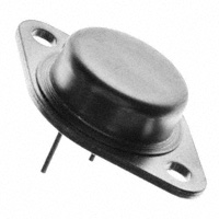


 工商网监
湘ICP备2023018690号
工商网监
湘ICP备2023018690号
