CP2108 Data Sheet
The CP2108 is a highly integrated USB to Quad UART Bridge
Controller providing a simple solution for updating RS-232/
RS-485 designs to USB using a minimum of components and
PCB space.
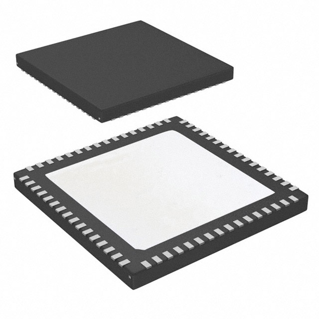
The CP2108 includes a USB 2.0 full-speed function controller, USB transceiver, oscillator, EEPROM, and four asynchronous serial data buses (UART) with full modem control signals in a compact 9 mm x 9 mm 64-pin QFN package. The on-chip EEPROM
may be used to customize the USB Vendor ID (VID), Product ID (PID), product description string, power descriptor, device release number, interface strings, device serial
number, modem and GPIO configuration as desired for applications. All customization
and configuration options can be selected using a simple GUI-based configurator. By
eliminating the need for complex firmware and driver development, the CP2108 devices enable quick USB connectivity with minimal development effort.
KEY FEATURES
• No firmware development required
• Simple GUI-based configurator
• Integrated USB transceiver; no external
resistors required
• Integrated clock; no external crystal
required
• USB 2.0 full-speed compatible
• Four independent UART interfaces
• 16 GPIOs with configurable options
• Royalty free Virtual COM port (VCP)
drivers
CP2108 is ideal for a wide range of applications, including the following:
• Servers
• Instrumentation
• Point-of-Sale products
• Industrial control
CP2108
Connect to VBUS or
External Supply
VREGIN
VDD
Voltage
Regulator
80 MHz
Oscillator
Baud Rate
Generator
RI(0-3)
Clock Divider
DCD(0-3)
DTR(0-3)
VSS
USB
Connector
VBUS
USB Interface
Handshake Control
VBUS
D+
D+
D-
D-
Full-Speed
12 Mbps
Transceiver
Peripheral
Function
Controller
Data
FIFO
RTS(0-3)
UART1
RX(0-3)
UARTn (0-3)
VIO
TX(0-3)
UART2
GPIO.0 – GPIO.15
18
/RESET
(2.7 to 6.0 V)
DSR(0-3)
CTS(0-3)
GND
(3.0 V to VDD)
6
UART0
VIO
VIOHD
EEPROM
(Product Customization)
SUSPEND
/SUSPEND
UART3
I/O Power and Logic Levels UART0-2, GPIO, SUSPEND, RESET
High Drive UART 3(Pins 1-6)
silabs.com | Building a more connected world.
Rev. 1.2
�CP2108 Data Sheet
Feature List and Ordering Information
1. Feature List and Ordering Information
CP
2108 – B 03 – G M R
Tape and Reel (Optional)
Package Type — QFN64
Temperature Grade — –40 to +85 °C (G)
Firmware Revision
Hardware Revision
Interface Family, USB-to-Quad-UART Bridge
Silicon Labs Xpress Product Line
Figure 1.1. CP2108 Part Numbering
The CP2108 devices have the following features:
• Single-Chip USB-to-QUAD UART Data Transfer
• Four independent UART interfaces
• Integrated USB transceiver; no external resistor required
• Integrated clock; no external crystal required
• Integrated programmable EEPROM for storing customizable product information
• On-chip power-on reset circuit
• On-chip voltage regulator: 3.3 V output
• USB Peripheral Function Controller
• USB Specification 2.0 compliant; full-speed (12 Mbps)
• USB suspend states supported via SUSPEND pins
• Virtual COM Port Drivers
• Works with existing COM port PC applications
• Royalty-free distribution license
• Supported on Windows, Mac, and Linux
• Supply Voltage
• Self-powered: 3.0 to 3.6 V
• USB bus powered: 4.0 to 5.5 V
• VIO voltage: 3.0 to VDD
• VIOHD voltage: 2.7 to 6 V
silabs.com | Building a more connected world.
• UART Interface Features
• Each UART interface supports the following:
• Supports hardware flow control (RTS/CTS)
• Supports all modem control signals
• Data formats supported:
• Data bits: 5, 6, 7, and 8
• Stop bits: 1, 1.5, and 2
• Parity: odd, even, set, mark and none
• Baud rates: 300 bps to 2 Mbps
• UART 3 (pins 1–6) supports interfacing to devices up to 6 V
• GPIO Interface Features
• Total of 16 GPIO pins with configurable options
• Suspend pin support
• Usable as inputs, open-drain or push-pull outputs
• 4 configurable clock outputs for external devices
• RS-485 bus transceiver control
• Toggle LED upon transmission
• Toggle LED upon reception
• Package Options
• RoHS-UART 3 compliant 64-pin QFN (9x9 mm)
• Temperature Range
• –40 to +85 °C
• Ordering Part Number
• CP2108-B03-GM
Rev. 1.2 | 2
�Table of Contents
1. Feature List and Ordering Information . . . . . . . . . . . . . . . . . . . . . . 2
2. System Overview . . . . . . . . . . . . . . . . . . . . . . . . . . . . . . 5
3. Electrical Specifications . . . . . . . . . . . . . . . . . . . . . . . . . . . 6
3.1 Electrical Characteristics . . . . . . . . . . . . .
3.1.1 Recommended Operating Conditions . . . . . . .
3.1.2 UART, GPIO, and Suspend I/O Electrical Characteristics
3.1.3 GPIO . . . . . . . . . . . . . . . . . .
3.1.4 Reset Electrical Characteristics . . . . . . . . .
3.1.5 Voltage Regulator . . . . . . . . . . . . .
3.1.6 USB Transceiver . . . . . . . . . . . . . .
.
.
.
.
.
.
.
.
.
.
.
.
.
.
.
.
.
.
.
.
.
.
.
.
.
.
.
.
.
.
.
.
.
.
.
.
.
.
.
.
.
.
.
.
.
.
.
.
.
.
.
.
.
.
.
.
.
.
.
.
.
.
.
.
.
.
.
.
.
.
.
.
.
.
.
.
.
.
.
.
.
.
.
.
.
.
.
.
.
.
.
3.2 Absolute Maximum Ratings .
.
.
.
.
.
.
.
.
.
.
.
.
.
.
.
.
.
.
.
.
.
.
.
.10
3.3 Thermal Conditions .
.
.
.
.
.
.
.
.
.
.
.
.
.
.
.
.
.
.
.
.
.
.
.
.
.11
3.4 Throughput and Flow Control.
.
.
.
.
.
.
.
.
.
.
.
.
.
.
.
.
.
.
.
.
.
.
.
.11
.
.
6
6
7
7
8
8
9
4. Pin Definitions . . . . . . . . . . . . . . . . . . . . . . . . . . . . . . 12
5. QFN64 Package Specifications. . . . . . . . . . . . . . . . . . . . . . . .
16
5.1 QFN64 Package Dimensions .
.
.
.
.
.
.
.
.
.
.
.
.
.
.
.
.
.
.
.
.
.
.
.
.16
5.2 QFN64 PCB Land Pattern .
.
.
.
.
.
.
.
.
.
.
.
.
.
.
.
.
.
.
.
.
.
.
.
.
.18
5.3 QFN64 Package Marking .
.
.
.
.
.
.
.
.
.
.
.
.
.
.
.
.
.
.
.
.
.
.
.
.
.19
6. Typical Connection Diagrams
. . . . . . . . . . . . . . . . . . . . . . . . 20
7. USB Function Controller and Transceiver
. . . . . . . . . . . . . . . . . . .23
8. Asynchronous Serial Data Bus (UART) Interfaces
8.1 Baud Rate Generation .
9. GPIO and UART Pins
.
.
.
.
.
.
.
.
.
. . . . . . . . . . . . . . . .24
.
.
.
.
.
.
.
.
.
.
.
.
.
.
.
.
.24
. . . . . . . . . . . . . . . . . . . . . . . . . . . 25
9.1 GPIO — Alternate Clock Outputs .
.
.
.
.
.
.
.
.
.
.
.
.
.
.
.
.
.
.
.
.
.
.25
9.2 GPIO — Transmit and Receive Toggle
.
.
.
.
.
.
.
.
.
.
.
.
.
.
.
.
.
.
.
.
.26
9.3 RS-485 Transceiver Bus Control
.
.
.
.
.
.
.
.
.
.
.
.
.
.
.
.
.
.
.
.
.27
9.4 Hardware Flow Control (RTS and CTS) .
.
.
.
.
.
.
.
.
.
.
.
.
.
.
.
.
.
.
.
.28
9.5 High Drive Pins UART 3 Pins 1–6 .
.
.
.
.
.
.
.
.
.
.
.
.
.
.
.
.
.
.
.
.29
10. Internal EEPROM
.
.
.
.
. . . . . . . . . . . . . . . . . . . . . . . . . . . . 30
11. CP2108 Device Drivers
. . . . . . . . . . . . . . . . . . . . . . . . . . 32
11.1 Virtual COM Port (VCP) Drivers
.
.
.
.
.
.
.
.
.
.
.
.
.
.
.
.
.
.
.
.
.
.
.32
11.2 Driver Customization .
.
.
.
.
.
.
.
.
.
.
.
.
.
.
.
.
.
.
.
.
.
.
.
.
.
.32
11.3 Driver Certification .
.
.
.
.
.
.
.
.
.
.
.
.
.
.
.
.
.
.
.
.
.
.
.
.
.
.32
.
12. Relevant Application Notes and Software
. . . . . . . . . . . . . . . . . . . 33
13. Revision History. . . . . . . . . . . . . . . . . . . . . . . . . . . . .
silabs.com | Building a more connected world.
34
Rev. 1.2 | 3
�13.1 Revision 1.2 .
.
.
.
.
.
.
.
.
.
.
.
.
.
.
.
.
.
.
.
.
.
.
.
.
.
.
.
.
.34
13.2 Revision 1.1 .
.
.
.
.
.
.
.
.
.
.
.
.
.
.
.
.
.
.
.
.
.
.
.
.
.
.
.
.
.34
13.3 Revision 1.0 .
.
.
.
.
.
.
.
.
.
.
.
.
.
.
.
.
.
.
.
.
.
.
.
.
.
.
.
.
.34
13.4 Revision 0.1 .
.
.
.
.
.
.
.
.
.
.
.
.
.
.
.
.
.
.
.
.
.
.
.
.
.
.
.
.
.34
silabs.com | Building a more connected world.
Rev. 1.2 | 4
�CP2108 Data Sheet
System Overview
2. System Overview
The CP2108 is a highly integrated USB-to-Quad-UART Bridge Controller providing a simple solution for updating RS-232/RS-485 designs to USB using a minimum of components and PCB space. The CP2108 includes a USB 2.0 full-speed function controller, USB
transceiver, oscillator, EEPROM, and four asynchronous serial data buses (UART) with full modem control signals in a compact 9 x 9
mm QFN-64 package (sometimes called “MLF” or “MLP”).
The on-chip EEPROM may be used to customize the USB Vendor ID (VID), Product ID (PID), Product Description String, Power Descriptor, Device Release Number, Interface Strings, Device Serial Number, Modem, and GPIO configuration as desired for OEM applications. The EEPROM is programmed on-board via the USB, allowing the programming step to be easily integrated into the product
manufacturing and testing process.
Royalty-free Virtual COM Port (VCP) device drivers provided by Silicon Labs allow a CP2108-based product to appear as four COM
ports in PC applications. The CP2108 UART interfaces implement all RS-232/RS-485 signals including control and handshaking, so
existing system firmware does not need to be modified. The device also features a total of sixteen GPIO signals that can be user-defined for status and control information. See www.silabs.com/appnotes for the latest application notes and product support information
for the CP2108.
An evaluation kit for the CP2108 is available. It includes a CP2108-based USB-to-UART/RS-232 evaluation board, a complete set of
VCP device drivers, USB and RS-232 cables, and full documentation. Contact a Silicon Labs sales representative or go to www.silabs.com/products/interface/Pages/CP2108EK.aspx to order the CP2108 Evaluation Kit.
silabs.com | Building a more connected world.
Rev. 1.2 | 5
�CP2108 Data Sheet
Electrical Specifications
3. Electrical Specifications
3.1 Electrical Characteristics
All electrical parameters in all tables are specified under the conditions listed in 3.1.1 Recommended Operating Conditions, unless stated otherwise.
3.1.1 Recommended Operating Conditions
VDD= 3.0 to 3.6 V, –40 to +85 °C unless otherwise specified.
Table 3.1. Recommended Operating Conditions1
Parameter
Symbol
Test Condition
Min
Typ
Max
Unit
Operating Supply Voltage VDD
VDD
3.0
—
3.6
V
Operating Supply Voltage VREGIN2
VREGIN
4.0
—
5.5
V
Operating Supply Voltage VIO
VIO
3.0
—
VDD
V
Operating Supply Voltage VIOHD
VIOHD
2.7
—
6.0
V
Supply Current—Normal 3
IDD
—
56
—
mA
Supply Current—Suspended 3
IDD
Bus Powered
—
460
—
µA
Self Powered
—
330
—
µA
Supply Current - USB Pull-up 4
IPU
—
200
228
µA
Operating Ambient Temperature
TA
-40
—
85
°C
Operating Junction Temperature
TJ
-40
—
105
°C
Note:
1. All voltages are with respect to VSS.
2. This applies only when using the regulator. When not using the regulator, VREGIN and VDD are tied together externally and it is
allowable for VREGIN to be equal to VDD.
3. If the device is connected to the USB bus, the USB pull-up current should be added to the supply current to calculate total required current.
4. The USB pull-up supply current values are calculated values based on USB specifications.
silabs.com | Building a more connected world.
Rev. 1.2 | 6
�CP2108 Data Sheet
Electrical Specifications
3.1.2 UART, GPIO, and Suspend I/O Electrical Characteristics
VDD= 3.0 to 3.6 V, VIO=1.8 V to VDD, VIOHD = 2.7 V to 6.0 V, –40 to +85 °C unless otherwise specified.
Table 3.2. UART, GPIO, and Suspend I/O
Parameter
Output High Voltage
Symbol
Test Condition
Min
Typ
Max
Unit
VOH
VIO – 0.7
—
—
V
VOH
VIOHD –
0.7
—
—
V
—
—
0.6
V
—
—
0.6
V
VIO – 0.6
—
—
V
—
—
0.6
V
(All pins except High Drive UART 3
pins 1–6)
Output High Voltage
(High Drive UART 3 pins 1–6)
Output Low Voltage
VOL
(All pins except High Drive pins 1–
6)
Output Low Voltage
Low Drive
IOL = 3 mA
VOL
(High Drive pins 1–6)
High Drive
IOL = 12.5 mA
Input High Voltage
VIH
3.0 ≤ VIO ≤ 3.6
Input Low Voltage
VIL
Weak Pull-up Current
IPU
VIO = 3.6 V
-30
-20
-10
µA
IPU
VIOHD = 2.7 V
-15
-10
-5
µA
VIOHD = 6.0 V
-30
-20
-10
µA
Min
Typ
Max
Unit
(VIN = 0 V)
Weak Pull-up Current UART 3
(pins 1–6)
3.1.3 GPIO
–40 to +85°C unless otherwise specified.
Table 3.3. GPIO Output Specifications
Parameter
Symbol
Test Condition
RS-485 Active Time After Stop Bit
tACTIVE
—
1
—
bit time1
TX Toggle Rate
fTXTOG
—
15
—
Hz
RX Toggle Rate
fRXTOG
—
15
—
Hz
Clock Output Rate
fCLOCK
~158k
—
20M
Hz
Note:
1. Bit-time is calculated as 1 / baud rate.
silabs.com | Building a more connected world.
Rev. 1.2 | 7
�CP2108 Data Sheet
Electrical Specifications
3.1.4 Reset Electrical Characteristics
–40 to +85 °C unless otherwise specified.
Table 3.4. Reset
Parameter
Power-On Reset (POR) Threshold
Symbol
Test Condition
Min
Typ
Max
Unit
VPOR
Rising Voltage on VDD
—
1.4
—
V
Falling Voltage on VDD
0.8
1
1.3
V
10
—
3000
µs
VIO – 0.6
—
—
V
VDD Ramp Time
tRMP
Time to VDD≥ 3.0 V
/RESET Input High Voltage
VIHRESET
3.0 ≤ VIO ≤ 3.6
/RESET Input Low Voltage
VILRESET
—
—
0.6
V
/RESET Low Time to Generate a
System Reset
tRSTL
50
—
—
ns
Min
Typ
Max
Unit
3.1.5 Voltage Regulator
–40 to +85 °C unless otherwise specified.
Table 3.5. Voltage Regulator
Parameter
Symbol
Test Condition
Output Voltage (at VDD pin)
VDDOUT
3.15
3.3
3.4
V
Output Current (at VDD pin)1
IDDOUT
—
—
150
mA
Output Load Regulation
VDDLR
—
0.1
1
mV/mA
Output Capacitance
CVDD
1
—
10
µF
Note:
1. This is the total current the voltage regulator is capable of providing. Any current consumed by the CP2108 reduces the current
available to external devices powered from VDD.
silabs.com | Building a more connected world.
Rev. 1.2 | 8
�CP2108 Data Sheet
Electrical Specifications
3.1.6 USB Transceiver
–40 to +85 °C unless otherwise specified.
Table 3.6. USB Transceiver
Parameter
Valid Supply Range
Symbol
Test Condition
VDD
Min
Typ
Max
Unit
3.0
—
3.6
V
(for USB Compliance)
VBUS Pull-Down Leakage Current
IVBUSL
VBUS = 5 V, VIO = 3.3 V
—
10
—
µA
VBUS Detection Input Threshold
VVBUSTH
3.0 ≤ VIO ≤ 3.6
VIO – 0.6
—
—
V
Transmitter
Output High Voltage
VOH
2.8
—
—
V
Output Low Voltage
VOL
—
—
0.8
V
Output Crossover Point
VCRS
1.3
—
2.0
V
Output Impedance
ZDRV
Driving High
—
38
—
Ω
Driving Low
—
38
—
Ω
1.425
1.5
1.575
kΩ
Low Speed
75
—
300
ns
Full Speed
4
—
20
ns
Low Speed
75
—
300
ns
Full Speed
4
—
20
ns
0.2
—
—
V
0.8
—
2.5
V
—


 工商网监
湘ICP备2023018690号
工商网监
湘ICP备2023018690号