S i 5 2 11 2 - B 5 / B 6
PCI-E XPRESS G EN 3 DUAL O UTPUT C LOCK G ENERATOR
Features
PCI-Express Gen 1, Gen 2, and
Gen 3 common clock compliant
Gen 3 SRNS Compliant
Low power HCSL differential
output buffers
Supports Serial-ATA (SATA) at
100 MHz
No termination resistors required
25 MHz Crystal Input or Clock
input
Triangular spread spectrum profile
for maximum EMI reduction
(Si52112-B6)
Extended Temperature:
–40 to 85 °C
3.3 V Power supply
Small packages:
8-pin TDFN (1.4 x 1.6 mm)
10-pin TDFN (3 x 3 mm)
Si52112-B5 does not support
spread spectrum outputs
Si52112-B6 supports 0.5% down
spread outputs
Ordering Information:
See page 13
Patents pending
Applications
Network attached storage
Multi-function printer
PCIe Add-on Cards
Network Interface Cards
Docking Stations
Wireless access point
Routers
Digital Still Cameras
Digital Video Cameras
Description
Si52112-B5/B6 is a high-performance, PCIe clock generator that can source
two PCIe clocks from a 25 MHz crystal or clock input. The clock outputs are
compliant to PCIe Gen 1, Gen 2, Gen 3 common clock, and Gen 3 SRNS
specifications. The ultra-small footprint (1.4 x 1.6 mm) and industry leading
low power consumption make Si52112-B5/B6 the ideal clock solution for
applications with tight board space constraints. Measuring PCIe clock jitter is
quick and easy with the Silicon Labs PCIe Clock Jitter Tool. Download it for
free at www.silabs.com/pcie-learningcenter.
Functional Block Diagram
VDD
DIFF1
XIN/CLKIN
PLL
Divider
DIFF2
XOUT
VSS
Rev 1.3 3/20
Copyright © 2020 by Silicon Laboratories
Si52112-B5/B6
�Si52112-B5/B6
TABLE O F C ONTENTS
Section
Page
1. Electrical Specifications . . . . . . . . . . . . . . . . . . . . . . . . . . . . . . . . . . . . . . . . . . . . . . . . . . .3
2. Crystal Recommendations . . . . . . . . . . . . . . . . . . . . . . . . . . . . . . . . . . . . . . . . . . . . . . . . .6
2.1. Crystal Loading . . . . . . . . . . . . . . . . . . . . . . . . . . . . . . . . . . . . . . . . . . . . . . . . . . . . . .6
2.2. Calculating Load Capacitors . . . . . . . . . . . . . . . . . . . . . . . . . . . . . . . . . . . . . . . . . . . .7
3. Test and Measurement Setup . . . . . . . . . . . . . . . . . . . . . . . . . . . . . . . . . . . . . . . . . . . . . . .8
4. Pin Descriptions . . . . . . . . . . . . . . . . . . . . . . . . . . . . . . . . . . . . . . . . . . . . . . . . . . . . . . . . . 10
4.1. 8-Pin TDFN . . . . . . . . . . . . . . . . . . . . . . . . . . . . . . . . . . . . . . . . . . . . . . . . . . . . . . . .10
4.2. 10-Pin TDFN . . . . . . . . . . . . . . . . . . . . . . . . . . . . . . . . . . . . . . . . . . . . . . . . . . . . . . .11
4.3. 8-Pin TSSOP . . . . . . . . . . . . . . . . . . . . . . . . . . . . . . . . . . . . . . . . . . . . . . . . . . . . . . .12
5. Ordering Guide . . . . . . . . . . . . . . . . . . . . . . . . . . . . . . . . . . . . . . . . . . . . . . . . . . . . . . . . . . 13
6. Package Outlines . . . . . . . . . . . . . . . . . . . . . . . . . . . . . . . . . . . . . . . . . . . . . . . . . . . . . . . .14
6.1. 8-Pin TDFN Package . . . . . . . . . . . . . . . . . . . . . . . . . . . . . . . . . . . . . . . . . . . . . . . . 14
6.2. 10-Pin TDFN Package . . . . . . . . . . . . . . . . . . . . . . . . . . . . . . . . . . . . . . . . . . . . . . . 16
6.3. TSSOP Package . . . . . . . . . . . . . . . . . . . . . . . . . . . . . . . . . . . . . . . . . . . . . . . . . . . . 18
7. Recommended Design Guideline . . . . . . . . . . . . . . . . . . . . . . . . . . . . . . . . . . . . . . . . . . . 20
Revision History . . . . . . . . . . . . . . . . . . . . . . . . . . . . . . . . . . . . . . . . . . . . . . . . . . . . . . . . . . . 21
Contact Information . . . . . . . . . . . . . . . . . . . . . . . . . . . . . . . . . . . . . . . . . . . . . . . . . . . . . . . .22
Rev 1.3
2
�Si52112-B5/B6
1. Electrical Specifications
Table 1. DC Electrical Specifications
Parameter
Symbol
Test Condition
Min
Typ
Max
Unit
Operating Voltage
VDD
3.3 V ± 5%
3.13
3.30
3.46
V
Operating Supply Current
IDD
Full Active
—
—
17
mA
Input Pin Capacitance
CIN
Input Pin Capacitance
—
3
5
pF
COUT
Output Pin Capacitance
—
—
5
pF
Output Pin Capacitance
Table 2. AC Electrical Specifications
Parameter
Symbol
Test Condition
Min
Typ
Max
Unit
LACC
Measured at VDD/2 differential
—
—
250
ppm
TDC
Measured at VDD/2
45
—
55
%
CLKIN Rise and Fall Times
TR/TF
Measured between 0.2 VDD
and 0.8 VDD
0.5
—
4.0
V/ns
CLKIN Cycle-to-Cycle Jitter
TCCJ
Measured at VDD/2
—
—
250
ps
CLKIN Long Term Jitter
TLTJ
Measured at VDD/2
—
—
350
ps
Input High Voltage
VIH
XIN/CLKIN pin
2
—
VDD+0.3
V
Input Low Voltage
VIL
XIN/CLKIN pin
—
—
0.8
V
Input High Current
IIH
XIN/CLKIN pin, VIN = VDD
—
—
35
µA
Input Low Current
IIL
XIN/CLKIN pin, 0 < VIN
很抱歉,暂时无法提供与“SI52112-B6-GM2R”相匹配的价格&库存,您可以联系我们找货
免费人工找货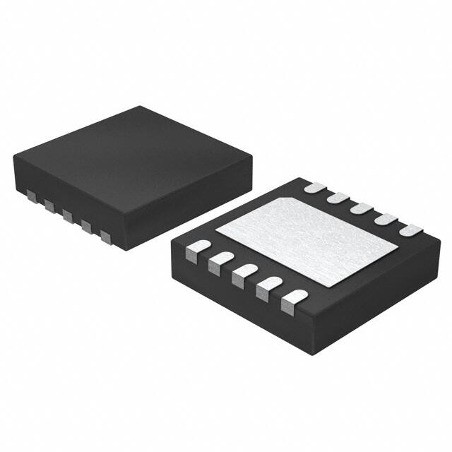


 工商网监
湘ICP备2023018690号
工商网监
湘ICP备2023018690号
