S i 5 2 1 3 1 - A 11 A
PCI-E X P R E S S G EN 1 , G E N 2, & G EN 3 TW O O U T P U T C LOCK G E N E R A T O R W I T H 25 MH Z R E F E RE NCE C LOCK & A C T I V E L OW OE P IN S
Features
22
21
20
19
1
18 OE_DIFF1
17 VDD_DIFF
REF
2
OE_REF1
3
VSS_REF
4
OE_DIFF01
5
VDD_DIFF
6
16 DIFF1
25
GND
15 DIFF1
14 DIFF0
13 DIFF0
7
8
Note
1. Internal 100 k-ohm pull-down resistor
9
10
11
12
VDD_DIFF
Si52131-A11A is a high-performance, PCIe clock generator that can
source two PCIe clocks and a buffered 25 MHz reference clock from a
25 MHz crystal or clock input. The PCIe clock outputs are compliant to
PCIe Gen 1, Gen 2, and Gen 3 specifications. The device has three
active low output enable pins for enabling and disabling each output. The
device features two input select pins for frequency selection and spread
control. The small footprint and low power consumption makes Si52131A11A the ideal clock solution for consumer and embedded applications.
23
1
1
Description
24
VDD_REF
SS0
Network Attached Storage
Wireless Access Point
Multi-function Printer
Routers
Ideal for Thunderbolt applications
SCLK
Applications
VDD_CORE
Pin Assignments
SDATA
NC
Ordering Information:
See page 17
XOUT
NC
XIN/CLKIN
NC
I2C support with readback
capabilities
Triangular spread spectrum
profile for maximum
electromagnetic interference
(EMI) reduction
Extended Temperature
–40 to 85oC
3.3 V Power supply
24-pin QFN package
SS1
25 MHz Crystal Input or Clock
input
VSS_CORE
PCI-Express Gen1, Gen2 &
Gen3 Compliant
Supports Serial ATA (SATA) at
100 MHz
Low power differential output
buffers
No termination resistors required
Dedicated active low output
enable pins for each output
Pin selectable spread control
Selectable frequencies: 100, 125,
and 200 MHz
Up two PCI-Express clocks
25 MHz reference clock
1
Patents pending
Functional Block Diagram
25MHz
XIN/CLKIN
XOUT
DIFF0
PLL1
(SSC)
Divider
DIFF1
SCLK
SDATA
Control & Memory
OE#_REF
OE#_DIFF [1:0]
Control
RAM
SSC [1:0]
Rev 1.0 3/13
Copyright © 2013 by Silicon Laboratories
Si52131-A11A
�Si52131-A11A
2
Rev 1.0
�Si52131-A11A
TABLE O F C ONTENTS
Section
Page
1. Electrical Specifications . . . . . . . . . . . . . . . . . . . . . . . . . . . . . . . . . . . . . . . . . . . . . . . . . . .4
2. Functional Description . . . . . . . . . . . . . . . . . . . . . . . . . . . . . . . . . . . . . . . . . . . . . . . . . . . .7
2.1. Crystal Recommendations . . . . . . . . . . . . . . . . . . . . . . . . . . . . . . . . . . . . . . . . . . . . .7
2.2. OE Pin Function . . . . . . . . . . . . . . . . . . . . . . . . . . . . . . . . . . . . . . . . . . . . . . . . . . . . .8
2.3. OE Assertion . . . . . . . . . . . . . . . . . . . . . . . . . . . . . . . . . . . . . . . . . . . . . . . . . . . . . . . .8
2.4. OE Deassertion . . . . . . . . . . . . . . . . . . . . . . . . . . . . . . . . . . . . . . . . . . . . . . . . . . . . . .8
2.5. SS[1:0] Pins Function . . . . . . . . . . . . . . . . . . . . . . . . . . . . . . . . . . . . . . . . . . . . . . . . .8
3. Test and Measurement Setup . . . . . . . . . . . . . . . . . . . . . . . . . . . . . . . . . . . . . . . . . . . . . . .9
4. Control Registers . . . . . . . . . . . . . . . . . . . . . . . . . . . . . . . . . . . . . . . . . . . . . . . . . . . . . . . .11
4.1. I2C Interface . . . . . . . . . . . . . . . . . . . . . . . . . . . . . . . . . . . . . . . . . . . . . . . . . . . . . . . 11
4.2. Data Protocol . . . . . . . . . . . . . . . . . . . . . . . . . . . . . . . . . . . . . . . . . . . . . . . . . . . . . .11
5. Si52131-A11A Pin Descriptions 24-Pin QFN . . . . . . . . . . . . . . . . . . . . . . . . . . . . . . . . . . 15
6. Ordering Guide . . . . . . . . . . . . . . . . . . . . . . . . . . . . . . . . . . . . . . . . . . . . . . . . . . . . . . . . . . 17
7. Package Outline . . . . . . . . . . . . . . . . . . . . . . . . . . . . . . . . . . . . . . . . . . . . . . . . . . . . . . . . . 18
Contact Information . . . . . . . . . . . . . . . . . . . . . . . . . . . . . . . . . . . . . . . . . . . . . . . . . . . . . . . .19
Rev 1.0
3
�Si52131-A11A
1. Electrical Specifications
Table 1. DC Electrical Specifications
Parameter
Symbol
Test Condition
Min
Typ
Max
Unit
3.3 V Operating Voltage
VDD core
3.3 ±5%
3.135
3.3
3.465
V
3.3 V Input High Voltage
VIH
SS1:0
2.0
—
VDD + 0.3
V
3.3 V Input Low Voltage
VIL
SS1:0
VSS – 0.3
—
0.8
V
Input High Voltage
VIHI2C
SDATA, SCLK
2.2
—
—
V
Input Low Voltage
VILI2C
SDATA, SCLK
—
—
1.0
V
Input High Leakage Current
IIH
Except internal pull-down
resistors, 0 < VIN < VDD
—
—
5
A
Input Low Leakage Current
IIL
Except internal pull-up resistors, 0 < VIN < VDD
–5
—
—
A
3.3 V Output High Voltage
(SE)
VOH
IOH = –1 mA
2.4
—
—
V
3.3 V Output Low Voltage
(SE)
VOL
IOL = 1 mA
—
—
0.4
V
High-impedance Output
Current
IOZ
–10
—
10
A
Input Pin Capacitance
CIN
1.5
—
5
pF
COUT
—
—
6
pF
LIN
—
—
7
nH
Power Down Current
IDD_PD
—
—
1
mA
Dynamic Supply Current
IDD_3.3V
—
—
45
mA
Output Pin Capacitance
Pin Inductance
4
All outputs enabled. Differential clocks with 5” traces
and 2 pF load. 25 MHz clock
with 5” traces and 4 pF load
Rev 1.0
�Si52131-A11A
Table 2. AC Electrical Specifications
Parameter
Symbol
Test Condition
Min
Typ
Max
Unit
LACC
Measured at VDD/2 differential
—
—
250
ppm
TDC
Measured at VDD/2
47
—
53
%
CLKIN Rise/Fall Slew Rate
TR/TF
Measured between 0.2 VDD and
0.8 VDD
0.5
—
4.0
V/ns
CLKIN Cycle to Cycle Jitter
TCCJ
Measured at VDD/2
—
—
250
ps
CLKIN Long Term Jitter
TLTJ
Measured at VDD/2
—
—
350
ps
Input High Voltage
VIH
XIN/CLKIN pin
2
—
VDD+0.3
V
Input Low Voltage
VIL
XIN/CLKIN pin
—
—
0.8
V
Input High Current
IIH
XIN/CLKIN pin, VIN = VDD
—
—
35
µA
Input Low Current
IIL
XIN/CLKIN pin, 0 < VIN
很抱歉,暂时无法提供与“SI52131-A11AGMR”相匹配的价格&库存,您可以联系我们找货
免费人工找货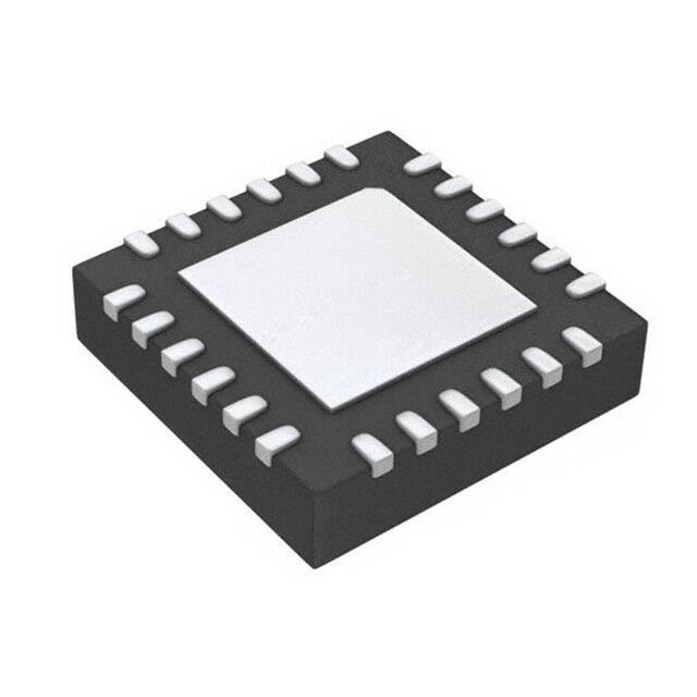


 工商网监
湘ICP备2023018690号
工商网监
湘ICP备2023018690号
