SENSORLESS-BLDC-MOTOR-RD
S E N S OR L E S S B L D C M O T O R R EFE RE N CE D E S I G N K I T U SE R ’ S G U I DE
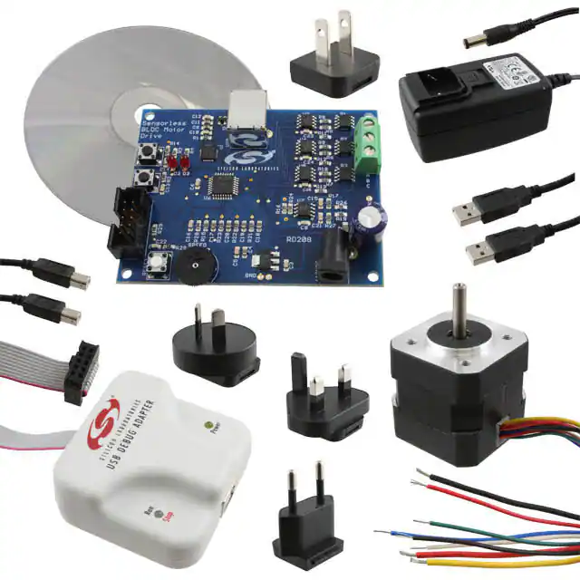
1. Kit Contents
The Sensorless BLDC Motor Reference Design Kit contains the following items:
Sensorless BLDC Motor Reference Design Board
Brushless DC (BLDC) Motor
Universal AC to 12 V DC Power Adapter
USB Debug Adapter
2 USB Cables
Reference Design Kit Tools & Documentation CD
2. Kit Overview
This reference design demonstrates sensorless control of a BLDC motor system using the C8051F310. The
reference design provides for both stand-alone demonstration operation and a simple user interface over USB. The
reference design may also be used as a platform for Sensorless BLDC motor code development.
This User's Guide provides a step-by-step guide for getting your system up and running. Refer to the Application
Note “AN208: Sensorless BLDC Reference Design“ for complete documentation of the Sensorless BLDC
Reference Design.
Figure 1. Sensorless BLDC Reference Design Board
Rev. 0.3 12/07
Copyright © 2007 by Silicon Laboratories
SENSORLESS-BLDC-MOTOR-RD
�SENSORLESS-BLDC-MOTOR-RD
3. Sensorless Motor Reference Design Demonstration
The Sensorless BLDC Motor Reference Design includes everything you need to set up a Sensorless BLDC motor
demonstration. Connect the BLDC motor to the Sensorless BLDC motor control board following the wiring chart for
the Anaheim Automation BLY171S-24V-4000 motor as shown in Table 1.
Table 1. BLDC Motor Wiring Diagram
Color
Location
Yellow
A
Red
B
Black
C
Connect the 12 V universal ac/dc power adapter to the dc supply (P1) on the Sensorless BLDC Motor Reference
Design Board. Rotate the SPEED knob fully clockwise. Press the START button on the Sensorless BLDC Motor
Reference Design Board. The motor will start running. Notice that the motor will first align and then smoothly speed
up to the minimum closed loop running speed. Rotate the knob counter clockwise to adjust the speed of the motor.
Press the STOP button and the motor will stop spinning.
Sensorless
BLDC
Motor
STOP
A
B
C
USB
START
RESET
DEBUG
Sensorless
BLDC Motor
Drive
SPEED
AC Adapter
Figure 2. Sensorless BLDC Motor Reference Design Demonstration Setup
2
Rev. 0.3
�SENSORLESS-BLDC-MOTOR-RD
4. Reference Design CD Installation
The included CD-ROM contains the Silicon Laboratories Sensorless BLDC Motor Reference Design software and
additional documentation.
Figure 3. Install Development Tools
The following steps detail the software installation process.
1. Place the Reference Design Kit CD-ROM into the PC.
2. An installation dialogue box will appear. Click the “Install Reference Design Kit Tools” button.
3. The Kit Selection window will open showing the available Reference Design Kits. To install the application,
select the "Sensorless BLDC Motor Reference Design Kit" option. Click the "Install" button.
4. The "Confirm Installations" window will open, showing the available installation options. Only the "Sensorless
BLDC Reference Design Kit" and "Install CP210x Drivers" needs to be selected to run the demo.
5. Follow the installation prompts to install the demo application. By default, the software will be installed in the
C:\SiLabs\MCU\SBLDC_Motor_RD directory.
6. Next, the CP210x Driver "unpacker" utility will run. Follow the steps to copy the driver files to the desired
location. The default directory is C:\SiLabs\MCU\CP210x.
7. The final window will give an option to install the driver on the target system. Select the “Launch the CP210x
VCP Driver Installer” option if you are ready to install the driver.
8. If selected, the driver installer will launch, providing an option to specify the driver installation location. After
pressing the “Install” button, the installer will search your system for copies of previously installed CP210x
Virtual COM Port drivers. It will let you know when your system is up to date. The driver files included in this
installation have been certified by Microsoft.
Rev. 0.3
3
�SENSORLESS-BLDC-MOTOR-RD
9. If the “Launch the CP210x VCP Driver Installer” option was not selected in step 7, the installer can be found in
the location specified in step 6, by default C:\SiLabs\MCU\CP210x\Windows_2K_XP_S2K3_Vista. At this
location, run CP210xVCPInstaller.exe.
10.To complete the installation process, connect the included USB cable between the host computer and the USB
connector on the SBLDC Motor. Windows will automatically finish the driver installation. Information windows
will pop up from the taskbar to show the installation progress.
11. If needed, the driver files can be uninstalled by selecting the “Silicon Laboratories CP210x USB to UART Bridge
(Driver Removal)” option in the “Add or Remove Programs” window.
4
Rev. 0.3
�SENSORLESS-BLDC-MOTOR-RD
5. HyperTerminal Demonstration
Before connecting the USB cable to your computer, make sure you have installed the Reference Design Kit Tools,
including the Virtual COM port driver by following the instructions in Section “4. Reference Design CD Installation”.
Start with the Demo Setup and add a USB cable connection to your computer as shown in Figure 4. The USB
connection is used with a terminal program to provide a basic terminal interface for the Sensorless BLDC motor.
Sensorless
BLDC
Motor
USB Cable
STOP
USB
START
Sensorless
BLDC Motor
Drive
RESET
DEBUG
SPEED
P1
AC Adapter
Figure 4. Sensorless BLDC Motor Reference Design Terminal Setup
Before opening HyperTerminal, you need to determine which COM port is being used for the Sensorless BLDC
Motor drive. Right-click on My Computer and select “Properties” (see Figure 5 on page 6). This will bring up the
System Properties window. Select the Hardware tab and then click on the Device Manager button. This will bring
up the Device Manager. Expand the Ports (COM & LPT) item. You should see the CP210x USB to UART bridge
controller with the COM port number. Use this COM port number when opening HyperTerminal.
Rev. 0.3
5
�SENSORLESS-BLDC-MOTOR-RD
Figure 5. Use the Device Manager to find your Virtual COM Port
Open the HyperTerminal application. The HyperTerminal program may be launched on most Windows XP systems
from the Start Menu:
StartProgramsAccessoriesCommunicationsHyperTerminal
Enter any name into the "Connection Description" dialog box as shown in Figure 6. In the "Connect To" dialog box,
choose the COM port corresponding to the Serial connection as determined from the Device Manager. In the
COM7 Properties dialog box, select 115200 baud and no flow control. Use the default settings of 8 data bits, no
parity, and one stop bit.
Figure 6. Setting Up HyperTerminal
6
Rev. 0.3
�SENSORLESS-BLDC-MOTOR-RD
Push the Reset button on the Sensorless BLDC Motor Reference Design Board. When reset, the Sensorless
BLDC Motor Reference Design sends the character string "push start button..." to the terminal. If you do not get a
“push start button...” prompt, check your port settings and cable connections, and make sure the Sensorless BLDC
Motor Reference Design Board is powered.
The Sensorless BLDC Motor Reference Design command line provides some basic terminal commands to display
motor state, status parameters, and change PI constants. Push the START button to start the motor. The motor
status will be displayed on the hyperterminal window. Once the motor is running, typing an “s” character
immediately displays the motor status. Refer to “AN208: Sensorless BLDC Motor Reference Design“ for a detailed
description of the command line interface.
Figure 7. Sensorless BLDC Motor Command Line
Rev. 0.3
7
�SENSORLESS-BLDC-MOTOR-RD
6. Development Setup using the USB Debug Adapter
The Sensorless BLDC Motor Reference Design includes everything you need to develop your own Sensorless
BLDC motor control firmware using the Silicon Laboratories C8051F310 MCU. The Sensorless BLDC Motor
reference design code may be used as a starting point for your own code development.
Connect the BLDC Motor and USB cable if you have not done so already. Refer to Table 1, “BLDC Motor Wiring
Diagram,” on page 2 for the BLDC motor connections. Connect the USB Debug Adapter ribbon cable to the 10-pin
Debug connector on the Sensorless BLDC Motor Reference Design Board. Connect the USB Debug Adapter to
your PC using the supplied USB cable as shown in Figure 8. Finally, connect the ac/dc power adapter to the
Sensorless BLDC Motor Reference Design Board.
To PC’s USB
port.
Sensorless
BLDC
Motor
USB Cable
STOP
USB
START
DEBUG
RESET
Power
Silicon Laboratories
USB DEBUG ADAPTER
Run
USB Cable
Stop
To PC’s USB
port.
Sensorless
BLDC Motor
Drive
SPEED
USB Debug
Adapter
P1
AC Adapter
Figure 8. Development Setup using the USB Debug Adapter
8
Rev. 0.3
�SENSORLESS-BLDC-MOTOR-RD
7. Sensorless BLDC Motor Project
The source code for the Sensorless BLDC Motor Reference design is installed from the CD onto your hard drive in
the following default location:
C:\SiLabs\MCU\SBLDC_Motor_RD\Firmware\
The software for AN208 is also available as a zip file on the CD or from the Silicon Laboratories website.
To create a Sensorless BLDC Motor Project, complete the following steps:
1. Launch the Silicon Laboratories IDE from the Start menu.
2. Select “Open Project” from the Project menu.
3. Browse to the source code location listed above, and open the file sbldc2k.wsp.
4. Double click on sbldc2k.c in the Project Workspace window to open.
5. Select “Rebuild All” from the project menu or click on the “Rebuild All” button. (The IDE will compile and link the
sbldc.c file as shown in Figure 9.)
6. Select “Connection Options” from the Options menu.
7. Make sure the USB Debug Adapter is selected and the Debug Interface is using the C2 connection.
8. Select “Connect” from the Debug menu, or click on the “Connect” button in the tool bar.
The Status Bar should display Target:C8051F310 to indicate the IDE is connected to the MCU on the Sensorless
BLDC Motor Reference Design Board. Refer to Application Note AN208 for additional information on the
Sensorless BLDC Motor code.
The sbldc2k.wsp workspace, which includes the sbldc2k.c module, will build a reduced functionality version of the
Sensorless BLDC motor code that does not include the HyperTerminal interface. This version may be built using
the 2 kB code size limited version of the Keil compiler. The full functionality workspace slbdc.wsp, which includes
the sbldc.c module, uses more than 4 kB of code and requires a full Keil compiler license.
The header file sbldc.h contains the motor parameters for the particular motor. The motor parameters must match
the motor you are using. Please check the header file to make sure the selected motor parameters match the
motor you are using.
Figure 9. Sensorless BLDC Motor Project
Rev. 0.3
9
�SENSORLESS-BLDC-MOTOR-RD
8. Related Documents
Sensorless BLDC Motor Reference Design Quick Start Guide
AN208: Sensorless Reference Design
Soft copies of this document and the ones listed above are included on the Reference Design Kit Tools &
Documentation CD. Click on Browse Documents to locate them or explore the CD and locate the User’s Guides
and Application Notes in the Documents folder.
The latest versions of the documentation and software can also be downloaded from the Silicon Laboratories
website www.silabs.com.
10
Rev. 0.3
�SENSORLESS-BLDC-MOTOR-RD
DOCUMENT CHANGE LIST
Updated sections 4 and 5 to include latest VCP
driver installation instructions.
Rev. 0.3
11
�Simplicity Studio
One-click access to MCU and
wireless tools, documentation,
software, source code libraries &
more. Available for Windows,
Mac and Linux!
IoT Portfolio
www.silabs.com/IoT
SW/HW
Quality
Support and Community
www.silabs.com/simplicity
www.silabs.com/quality
community.silabs.com
Disclaimer
Silicon Laboratories intends to provide customers with the latest, accurate, and in-depth documentation of all peripherals and modules available for system and software implementers
using or intending to use the Silicon Laboratories products. Characterization data, available modules and peripherals, memory sizes and memory addresses refer to each specific
device, and "Typical" parameters provided can and do vary in different applications. Application examples described herein are for illustrative purposes only. Silicon Laboratories
reserves the right to make changes without further notice and limitation to product information, specifications, and descriptions herein, and does not give warranties as to the accuracy
or completeness of the included information. Silicon Laboratories shall have no liability for the consequences of use of the information supplied herein. This document does not imply
or express copyright licenses granted hereunder to design or fabricate any integrated circuits. The products must not be used within any Life Support System without the specific
written consent of Silicon Laboratories. A "Life Support System" is any product or system intended to support or sustain life and/or health, which, if it fails, can be reasonably expected
to result in significant personal injury or death. Silicon Laboratories products are generally not intended for military applications. Silicon Laboratories products shall under no
circumstances be used in weapons of mass destruction including (but not limited to) nuclear, biological or chemical weapons, or missiles capable of delivering such weapons.
Trademark Information
Silicon Laboratories Inc., Silicon Laboratories, Silicon Labs, SiLabs and the Silicon Labs logo, CMEMS®, EFM, EFM32, EFR, Energy Micro, Energy Micro logo and combinations
thereof, "the world’s most energy friendly microcontrollers", Ember®, EZLink®, EZMac®, EZRadio®, EZRadioPRO®, DSPLL®, ISOmodem ®, Precision32®, ProSLIC®, SiPHY®,
USBXpress® and others are trademarks or registered trademarks of Silicon Laboratories Inc. ARM, CORTEX, Cortex-M3 and THUMB are trademarks or registered trademarks of
ARM Holdings. Keil is a registered trademark of ARM Limited. All other products or brand names mentioned herein are trademarks of their respective holders.
Silicon Laboratories Inc.
400 West Cesar Chavez
Austin, TX 78701
USA
http://www.silabs.com
�


 工商网监
湘ICP备2023018690号
工商网监
湘ICP备2023018690号
