S2-LP
Datasheet
Ultra-low power, high performance, sub-1 GHz transceiver
Features
•
•
•
•
Maturity status link
S2-LP
•
•
•
•
•
•
•
•
•
•
•
•
•
•
•
•
•
•
•
•
•
•
•
•
•
•
Frequency bands:
413-479 MHz (S2-LPQTR)
–
–
452-527 MHz (S2-LPCBQTR)
–
826-958 MHz (S2-LPQTR)
–
904-1055 MHz (S2-LPCBQTR)
Modulation schemes:
–
2(G)FSK, 4(G)FSK
–
OOK, ASK
Air data rate from 0.1 to 500 kbps
Ultra-low power consumption:
–
7 mA RX
–
10 mA TX @ +10 dBm
Excellent performance of receiver sensitivity: down to -130 dBm
Excellent receiver selectivity and blocking
Programmable RF output power up to +16 dBm
Programmable RX digital filter
Programmable channel spacing
Fast start-up and frequency synthesizer settling time
Automatic frequency offset compensation, AGC and symbol timing recovery
More than 145 dB RF link budget
Battery indicator and low battery detector
RX and TX 128 bytes FIFO buffers
4-wire SPI interface
Automatic packet acknowledgment and retransmission
Embedded timeout protocol engine
Excellent receiver selectivity (> 80 dB @ 2 MHz)
ST companion integrated balun/filter chips are available
Antenna diversity algorithm
Fully integrated ultra-low power RC oscillator
Wake-up driven by internal timer or external event
Digital real time RSSI
Flexible packet length with dynamic payload length
Programmable preamble and SYNC word quality filtering and detection
Embedded CSMA/CA engine based on listen-before-talk systems
IEEE 802.15.4g hardware packet support with whitening, FEC, CRC and dual
SYNC word detection
Wireless M-BUS supported
KNX-RF supported
Enables operations in the SIGFOX™ and MONARCH networks
DS11896 - Rev 10 - June 2022
For further information contact your local STMicroelectronics sales office.
www.st.com
�S2-LP
•
•
Suitable to build systems targeting:
–
Europe: ETSI EN 300 220, category 1.5 natively compliant, ETSI EN 303
131
–
US: FCC part 15 and part 90
–
Japan: ARIB STD T67, T108
–
China: SRRC
Operating temperature range: -40 °C to +105 °C
Applications
•
•
•
•
•
•
•
•
DS11896 - Rev 10
Sensors to Cloud
Smart metering
Home energy management systems
Wireless alarm systems
Smart home
Building automation
Industrial monitoring and control
Smart lighting systems
page 2/91
�S2-LP
Description
1
Description
The S2-LP is a high performance ultra-low power RF transceiver, intended for RF wireless applications in the
sub-1 GHz band. It is designed to operate in both the license-free ISM and SRD frequency bands at 433, 512,
868 and 920 MHz, but can also be programmed to operate at other additional frequencies in the 413-479 MHz,
452-527 MHz, 826-958 MHz, 904-1055 MHz bands.
The S2-LP supports different modulation schemes: 2(G)FSK, 4(G)FSK, OOK and ASK. The air data rate is
programmable from 0.1 to 500 kbps.
The S2-LP can be used in systems with channel spacing down to 1 kHz enabling the narrow band operations.
The S2-LP shows an RF link budget higher than 140 dB for long communication ranges and meets the regulatory
requirements applicable in territories worldwide, including Europe, Japan, China and the USA.
DS11896 - Rev 10
page 3/91
�S2-LP
Detailed functional description
2
Detailed functional description
The S2-LP integrates a configurable baseband modem with proprietary fully programmable packet format
allowing also:
•
IEEE 802.15.4g applications
The hardware packet supports whitening, CRC, FEC and dual SYNC word detection.
–
•
Wireless M-Bus applications
In order to reduce the overall system power consumption and increase the communication reliability, the S2LP provides an embedded programmable automatic packet acknowledgment, automatic packet retransmission,
CSMA/CA engine, low duty cycle protocol, RX sniff mode and timeout protocol.
The S2-LP fully supports antenna diversity with an integrated antenna switching control algorithm.
Transmitted/received data bytes are buffered in two different 128 bytes FIFOs (TX FIFO and RX FIFO),
accessible via SPI interface for host processing.
In addition, the reduced number of external components enables a cost effective solution permitting a compact
PCB footprint.
The S2-LP targets volume applications like:
•
Sensors to Cloud
•
Smart metering
•
Home energy management systems
•
Wireless alarm systems
•
Smart home
•
Building automation
•
Industrial monitoring and control
Figure 1. Simplified S2-LP block diagram
DS11896 - Rev 10
page 4/91
�S2-LP
Detailed functional description
The receiver architecture is low-IF conversion, the received RF signal is amplified by a two-stage low-noise
amplifier (LNA) and down-converted in quadrature (I and Q) to the intermediate frequency (IF). LNA and IF
amplifiers make up the RX front-end (RXFE) and have programmable gain. At IF, the ADCs digitalize the I/Q
signals. The demodulated data go to an external MCU either through the 128-byte RX FIFO, readable via SPI, or
directly using a programmable GPIO pin.
The transmitter part of the S2-LP is based on direct synthesis of the RF frequency. The power amplifier (PA) input
is the LO generated by the RF synthesizer, while the output level can be configured between -30 dBm and +14
dBm (+16 dBm in boost mode), at antenna level with 0.5 dB steps.
The data to be transmitted can be provided by an external MCU either through the 128-byte TX FIFO writable
via SPI, or directly using a programmable GPIO pin. The S2-LP supports frequency hopping, TX/RX and antenna
diversity switch control, extending the link range and improving performance.
The S2-LP has a very efficient power management (PM) system. An integrated switched mode power supply
(SMPS) regulator allows operation from a battery voltage ranging from +1.8 V to +3.6 V, and with power
conversion efficiency of 90%.
A crystal must be connected between XIN and XOUT. It is digitally configurable to operate with different crystals.
As an alternative, an external clock signal can be used to feed XIN for proper operation. The S2-LP also has an
integrated low-power RC oscillator, generating the 34.7 kHz signal used as a clock for the slowest timeouts.
A standard 4-pin SPI bus is used to communicate with the external MCU. Four configurable general purpose I/Os
are available.
DS11896 - Rev 10
page 5/91
�S2-LP
Typical application diagram and pin description
3
Typical application diagram and pin description
This section describes three different application diagrams for the S2-LP. Two main configurations are available:
•
HPM (high performance mode) configuration
LPM (low power mode) configuration
•
In the LPM operating mode the LDOs are bypassed and the SMPS provides the regulator voltage at 1.2 V. Note
that in LPM the PA is supplied from SMPS at 1.2 V (instead of 1.5 V as in HPM), so the max. output power
is lower than HPM. The figure below shows the suggested configuration with discrete matching network and
SMPS-ON.
Figure 2. Suggested application diagram (embedded SMPS used)
Digital interface
VRDIG
GPIO3
GPIO2
GPIO1
GPIO0
CSN
24
23
22
21
20
19
C0
VBATT
VSMPS2
VBATT
VDDSMPS
SMPS1
SMPS2
XOUT
XIN
SDN
C3
SHUTDOWN
18
17
16
15
14
13
C17
C13
C14
L5
C11
7
8
9
10
11
12
S2-LP
SCLK
SDI
SDO
VDDRXDIG
RXP
RXN
GND
XTAL
1
2
3
4
5
6
C10
L6
L3
25
C2
L0
VDDANASYNTH
VRSYNTH
VREFVCO
VDDVCOTX
TX
VRRF
C1
C6
C16
C5
VBATT
VBATT
C4
C28
L7
VSMPS2
C30
C21
L10
L9
L8
C29
C31
C32
Figure 3. Suggested application diagram (embedded SMPS not used) shows the suggested configuration with
discrete matching network and SMPS-OFF mode.
DS11896 - Rev 10
page 6/91
�S2-LP
Typical application diagram and pin description
Figure 3. Suggested application diagram (embedded SMPS not used)
Digital interface
24
23
22
21
20
19
C0
VRDIG
GPIO3
GPIO2
GPIO1
GPIO0
CSN
U3
VBATT
VBATT
XTAL
C3
SHUTDOWN
C14
L5
C11
7
8
9
10
11
12
S2-LP
C17
C13
GND
C2
18
17
16
15
14
13
SCLK
SDI
SDO
VDDRXDIG
RXP
RXN
L6
C10
L3
25
EXT 1.2-1.8V = VSMPS2
VDDSMPS
SMPS1
SMPS2
XOUT
XIN
SDN
VDDANASYNTH
VRSYNTH
VREFVCO
VDDVCOTX
TX
VRRF
1
2
3
4
5
6
C6
C16
C5
VBATT
VBATT
C4
C28
L7
VSMPS2
C29
C30
C21
L10
L9
L8
C31
C32
Figure 4. Suggested application diagram HPM/LPM (integrated balun, embedded SMPS used)
Digital interface
VRDIG
GPIO3
GPIO2
GPIO1
GPIO0
CSN
24
23
22
21
20
19
C0
VBATT
VSMPS2
VBATT
VDDSMPS
SMPS1
SMPS2
XOUT
XIN
SDN
C3
SHUTDOWN
7
8
9
10
11
12
S2-LP
SCLK
SDI
SDO
VDDRXDIG
RXP
RXN
GND
XTAL
1
2
3
4
5
6
18
17
16
15
14
13
RX_P
RX_N
GND
ANT
TX
GND
C16
BALF-SPI2
25
C2
L0
VDDANASYNTH
VRSYNTH
VREFVCO
VDDVCOTX
TX
VRRF
C1
C6
C5
C21
VBATT
VBATT
C4
L7
VSMPS2
DS11896 - Rev 10
page 7/91
�S2-LP
Typical application diagram and pin description
Table 1. Description of the external components of the typical application diagrams
DS11896 - Rev 10
HPM/LPM discrete balun
Description
SMPS ON
SMPS OFF
HPM/LPM
integrated balun
C0
X
X
X
Decoupling capacitor for on-chip voltage regulator to
digital part
C1
X
-
X
SMPS LC filter capacitors
C2, C3
X
X
X
Crystal loading capacitors
C4
X
X
X
Decoupling capacitor for on-chip voltage regulator to
synthesizer (LF part)
C5
X
X
X
Decoupling capacitor for band-gap voltage reference
of VCO regulator
C6
X
X
X
Decoupling capacitor for on-chip voltage regulator to
LNA-MIXER
C29, C30, C31, C32
X
X
TX LC filter/matching capacitors
C11, C13
X
X
DC blocking capacitors
C16, C21
X
X
C10, C14, C17
X
X
L0
X
-
X
SMPS LC filter inductor
L7
X
X
X
RF choke inductor or resonating inductor (upon RF
network topology)
L8, L9, L10
X
X
TX LC filter/matching inductors
L3, L5, L6
X
X
RX balun/matching inductors
XTAL
X
X
Components
X
RF balun/matching capacitors
X
Crystal
page 8/91
�S2-LP
Pin diagram
3.1
Pin diagram
20
CSn
21
GPIO 0
22
GPIO 1
23
GPIO 2
24
GPIO 3
VR DIG
Figure 5. Pin diagram, QFN24 (4x4 mm) package
19
SCLK
VDD SMPS
18
1
SDI
SMPS1
S2-LPQTR
2
17
SMPS2
SDO
16
3
VDD DIG/RX
XOUT
15
4
RX+
XIN
14
5
RX-
SDN
13
6
3.2
11
VR RF
10
TX
9
VDD TX/VCO
8
VREF VCO
7
VR SYNTH
VDD ANA/SYNTH
25 - GND
12
Pin description
Table 2. Pinout
DS11896 - Rev 10
Number
Pin name
Pin type
Description
1
VDD SMPS
Power
1.8 V to 3.6 V analog power supply for SMPS only.
2
SMPS1
Analog out
1.1 V to 1.8 V SMPS regulator output to be externally filtered
3
SMPS2
Analog in
1.1 V to 1.8 V SMPS voltage input after LC filtering applied to SMPS1 output
4
XOUT
Analog out
Crystal oscillator output. Connect to an external crystal or leave floating if driving
the XIN pin with an external clock source
5
XIN
Analog in
Crystal oscillator input. Connect to an external crystal or to an external clock
source. If using an external clock source, DC coupling with a minimum 0.2 VDC
level is recommended and minimum AC amplitude of 400 mVpp (however, the
instantaneous level at input cannot exceed the 0 – 1.4 V range)
6
SDN
Digital in
Shutdown input pin. SDN should be = ‘0’ in all modes, except shutdown mode
7
VDD ANA/
SYNTH
Power
1.8 V to 3.6 V power
8
VR SYNTH
Analog in/out
1.2 V SYNTH-LDO output for decoupling
9
VREF VCO
Analog out
1.2 V VCO-LDO band-gap reference voltage decoupling
10
VDD VCO/TX
Power
1.8 V to 3.6 V power supply
11
TX
RF output
RF output signal
page 9/91
�S2-LP
Pin description
DS11896 - Rev 10
Number
Pin name
Pin type
Description
12
VR RF
Analog in/out
1.2 V RX-LDO output for decoupling
13
RXn
RF in
14
RXp
RF in
15
VDD RX/DIG
Power
1.8 V to 3.6 V power supply
16
SDO
Digital out
SPI slave data output
17
SDI
Digital in
SPI slave data input
18
SCLK
Digital in
SPI slave clock input
19
CSn
Digital in
SPI chip select
20
GPIO0
Digital I/O
21
GPIO1
Digital I/O
22
GPIO2
Digital I/O
23
GPIO3
Digital I/O
24
VR DIG
Analog in/out
1.2 V digital power supply output for decoupling
25
GND
Ground
Exposed pad connected to the ground of the application board
Differential RF input signals for the LNA
General purpose I/O that may be configured through the SPI registers to perform
various functions
page 10/91
�S2-LP
Specifications
4
Specifications
4.1
Absolute maximum ratings
Absolute maximum ratings are those values above which damage to the device may occur. Functional operation
under these conditions is not implied. All voltages refer to GND.
Table 3. Absolute maximum ratings
Parameter
Min.
Typ.
Max.
Supply and SMPS pins
-0.3
+3.9
DC voltage on VREG pins
-0.3
+3.9
DC voltage on digital input pins
-0.3
+3.9
DC voltage on digital output pins
-0.3
+3.9
DC voltage on ground pins
-0.3
+3.9
DC voltage on analog pins
-0.3
+1.8
DC voltage on TX pin
-0.3
+3.9
Storage temperature range
-40
+125
°C
1000
V
VESD-HBM
4.2
Unit
V
Operating range
Table 4. Operating range
Parameter
Min.
Typ.
Max.
Unit
Operating battery supply voltage (VBAT)
1.8(1)
3.0
3.6
V
Operating ambient temperature range
-40
25
+105
°C
1. 2 V when the device works in boost mode with SMPS ON.
4.3
Thermal properties
Table 5. Thermal data
4.4
Parameter
QFN24
Unit
Thermal resistance junction-ambient
66
°C/W
Power consumption
Characteristics measured over recommended operating conditions unless otherwise specified. Typical values
are referred to 25 °C temperature, VBAT = 3.3 V. All performance is referred to the STEVAL-FKI433V2 or
STEVAL-FKI868V2 with a 50 Ohm antenna connector.
DS11896 - Rev 10
page 11/91
�S2-LP
Power consumption
Table 6. Low-power state power consumption
Parameter
Test conditions
Supply current
Min.
Typ.
Shutdown
2.5
Standby
500
Sleep
-
Max.
nA
700
Sleep (FIFOs retained)
0.95
Ready
350
Unit
µA
Table 7. Power consumption in reception TA = 25 °C, VDD = 3.3 V, fc = 868 MHz
Parameter
Test conditions
Min.
RX @ sensitivity level
RX in sniff mode @ 1.2 kbps
Supply current
(1)
RX in LDC mode @ 38.4 kbps (4)
LPM typ.
8.6
7.2
Max.
0.9
RX in sniff mode @ 38.4 kbps (2)
RX in LDC mode @ 1.2 kbps (3)
HPM typ.
Unit
mA
0.8
-
21
µA
3
1. Using 2-FSK, FREQDEV = 2.4 kHz, DR=1.2 kbps, 4 bytes preamble and 8 kHz ch. filter. Where the receiver wakes up at
regular intervals to look for an incoming packet.
2. Using 2-FSK, FREQDEV = 20 kHz, DR=38.4 kbps, 24 bytes preamble and 100 kHz ch. filter. Where the receiver wakes up
at regular intervals to look for an incoming packet.
3. Check for data packet every 1 second in LDC mode. 2-FSK, FREQDEV = 1.2 kHz DEV and 8 kHz ch. filter, DR=1.2 kbps,
internal RC oscillator used as sleep timer. Sniff timer enabled.
4. Check for data packet every 1 second in LDC mode. 2-FSK, FREQDEV = 20 kHz, DR=38.4 kbps and 100 kHz ch. filter,
internal 34.6 kHz RC oscillator used as sleep timer. Sniff timer enabled.
Table 8. Power consumption in transmission fc= 915 MHz
Parameter
Test conditions
Supply current
Min.
Typ.
TX CW @ 14 dBm
22
TX CW @ 10 dBm(1)
12.5
TX CW @ 16 dBm in Boost (2)
32
Max.
Unit
mA
1. SMPS output voltage 1.2 V, LDOs disable.
2. SMPS output voltage 1.8 V.
Table 9. Power consumption in transmission fc= 840-868 MHz
Parameter
Test conditions
Min.
Typ.
TX CW @ 14 dBm
Supply current
TX CW @ 10
Max.
20
dBm(1)
mA
11.5
TX CW @ 16 dBm in Boost (2)
Unit
29
1. SMPS output voltage 1.2 V, LDOs disable.
2. SMPS output voltage 1.8 V.
Table 10. Power consumption in transmission fc= 434 MHz
DS11896 - Rev 10
Parameter
Test conditions
Supply current
TX CW @ 14 dBm(1)
Min.
Typ.
21
Max.
Unit
mA
page 12/91
�S2-LP
General characterization
Parameter
Test conditions
Min.
Supply current
TX CW @ 10 dBm(2)
Typ.
Max.
Unit
mA
11.5
1. SMPS output voltage 1.6 V.
2. SMPS output voltage 1.2 V, LDOs disable.
Table 11. Power consumption in transmission fc = 510 MHz
Parameter
Test conditions
Supply current
Min.
Typ.
TX CW @ 14 dBm
19
TX CW @ 10 dBm(1)
12
TX CW @ 15 dBm(2)
27
Max.
Unit
mA
1. SMPS output voltage 1.2 V, LDOs disable.
2. SMPS output voltage 1.8 V.
4.5
General characterization
Table 12. General characteristics
Parameter
Typ.
Unit
413 - 479
452-527
Frequency range
MHz
826 - 958
904-1055
Data rate DR
2-(G)FSK
0.1 - 250
4-(G)FSK
0.2 - 500
OOK/ASK
0.1 -125
kbps
Data rate accuracy
±100
ppm
Frequency deviation FDEV
0.15 - 500
kHz
If "Manchester" or "3-out-of-6" or FEC coding options are enabled the actual bit rate is affected as follows:
Table 13. Data rate with different coding options
DS11896 - Rev 10
Coding option
2GFSK[kbps]
4GFSK[kbps]
NRZ
250
500
FEC
125
250
Manchester
125
Not supported
3-out-of-6
166.6
Not supported
page 13/91
�S2-LP
Frequency synthesizer
4.6
Frequency synthesizer
Table 14. Frequency synthesizer parameters
Parameter
Test conditions
50 MHz
Unit
Frequency step size
Out-loop divider ratio = 4
23.8
Hz
10 kHz
-109
100 kHz
-110
1 MHz
-124
10 MHz
-141
10 kHz
-108
100 kHz
-109
1 MHz
-124
10 MHz
-140
10 kHz
-102
100 kHz
-103
1 MHz
-117
10 MHz
-138
10 kHz
-102
100 kHz
-102
1 MHz
-117
10 MHz
-138
RF carrier phase noise 433 MHz
RF carrier phase noise 510 MHz
RF carrier phase noise 868 MHz
RF carrier phase noise 915 MHz
4.7
dBc/Hz
Crystal oscillator
Characteristics measured over recommended operating conditions unless otherwise specified. All typical values
are referred to 25 °C temperature, VBAT = 3.0 V.
The device supports crystals in the range [24-26] MHz and [48-52] MHz.
If the crystal is in the [24–26] MHz range, both the analog and the digital parts must work at this frequency.
Otherwise, if a crystal in the [48-52] MHz range is used, the analog part must work at this frequency and the
digital part at this frequency divided by 2. From now on in this document the XTAL oscillator will be indicated with
fXO and the digital clock with fdig
The divider for the digital part can be set by the PD_CLKDIV bit of the XO_RCO_CONFIG1 in the following way:
•
if a [48 – 52] MHz crystal is used, this bit must be 0 (digital divider enabled):
•
f
fdig = xo
2
(1)
if a [24 – 26] MHz crystal is used, this bit must be 1 (digital divider disabled):
fdig = fxo
(2)
The safest procedure to disable the divider without any risk of glitches in the digital clock is to switch into
STANDBY mode, hence, disable the divider through register setting, and then come back to the READY state.
In order to avoid potential RF performance degradations, the crystal frequency should be chosen to satisfy the
following equation:
F
nFCH − ROUND n CH fXO ≥ 1MHz
fXO
(3)
where n is an integer in the set [1-7, B] (B is the synthesizer’s divider ratio).
DS11896 - Rev 10
page 14/91
�S2-LP
RF receiver
Table 15. Crystal oscillator characteristics
Parameter
Test conditions
Crystal frequency
Min. Typ. Max.
24
26
48
52
Frequency tolerance (1)
MHz
± 40
Minimum requirement on external reference phase noise mask
fXO = 26 MHz, to avoid degradation on synthesizer phase/noise
ppm
10 kHz
-135
100 kHz
-140
1 MHz
-140
10 MHz
Programmable trans-conductance of the oscillator at start-up
VBAT=1.8 V,
fXO = 26 MHz
dBc/Hz
-140
43
13
Start-up time (2)
Unit
mS
100
µs
1. Including initial tolerance, crystal loading, aging, and temperature dependence. The acceptable crystal tolerance depends
on RF frequency and channel spacing/bandwidth.
2. Start-up times are crystal dependent. The crystal oscillator trans-conductance can be tuned to compensate the variation of
crystal oscillator series resistance.
Table 16. Ultra-low power RC oscillator
Parameter
Test conditions
Typ.
Calibrated frequency
Calibrated RC oscillator frequency is derived from crystal oscillator
frequency.
Unit
33.3 (1) kHz
Frequency accuracy after calibration
±1
%
1. Depending on the crystal frequency, the reported value is referring to 50 MHz.
4.8
RF receiver
Characteristics measured over recommended operating conditions unless otherwise specified. All typical values
are referred to 25 °C temperature, VBAT = 3.3 V, no frequency offset in the RX signal. The whole performance is
referred to the STEVAL-FKI433V2, STEVAL-FKI512V1 or STEVAL-FKI868V2 with a 50 Ohm antenna connector.
Table 17. RF receiver characteristics
Parameter
Test conditions
Receiver channel bandwidth
CHF
DS11896 - Rev 10
HPM/LPMSMPS
on typ.
Unit
1-800
kHz
433 MHz
-15
868 MHz
-15
433 MHz
10
868 MHz
10
Interferers are continuous wave @ 6 MHz and 12 MHz 433 MHz
Input third order intercept point
offset from carrier
868 MHz
-25
RX input return loss
Max. RX gain, tied (RX + TX) matching networks
Saturation 1% BER
2-FSK 1.2 kHz FDEV, DR = 1.2 kbps, CHF = 4 kHz
8
868 MHz
8
Max. RX gain
433 MHz
200 // 1.5
R // C
868 MHz
200 // 1.5
Max. RX gain, tied (RX + TX) matching networks
Differential input impedance at
LNA
dBm
-25
433 MHz
RX noise figure
dB
dB
Ω//pF
page 15/91
�S2-LP
RF receiver
4.8.1
Blocking and selectivity at 433 MHz
Table 18. Blocking and selectivity at 433 MHz
Test condition
HPM
SMPS on
(typ.)
+12.5 kHz (adjacent
channel)
64
56
-12.5 kHz (adjacent
channel)
64
56
+25 kHz (alternate
channel)
65
59
-25 kHz (alternate
channel)
65
59
Image rejection
60
63
±2 MHz
81
81
±10 MHz
82
85
+100 kHz (adjacent
channel)
50
37
-100 kHz (adjacent
channel)
50
37
+200 kHz (alternate
channel)
51
45
-200 kHz (alternate
channel)
51
45
Image rejection
56
58
±2 MHz
67
67
±10 MHz
69
72
Parameter
Selectivity and blocking 1%
BER @ 2-GFSK BT=0.5 1.2 kHz FDEV, DR = 1.2 kbps, CHF = 4 kHz
Selectivity and blocking 1%
BER @ 2-GFSK BT=0.5 20 kHz FDEV, DR = 38.4 kbps, CHF = 100 kHz
4.8.2
LPM
SMPS ON Unit
typ.
dB
dB
Sensitivity at 433 MHz
Table 19. Sensitivity at 433 MHz
Parameter
Test conditions
HPM/LPM SMPS on (typ.)
DR = 0.3 kbps, FDEV = 0.25 kHz, CHF = 1 kHz
-128
Sensitivity
DR = 1.2 kbps, FDEV = 1.2 kHz, CHF = 4 kHz
-122
1% BER @ 2-GFSK BT = 0.5
DR = 38.4 kbps, FDEV = 20 kHz, CHF = 100 kHz
-109
DR = 250 kbps, FDEV = 125 kHz, CHF = 780 kHz
-101
DR = 4.8 ksps, DEV = 2.4 kHz, CHF = 10 kHz
-114
DR = 9.6 ksps, DEV = 4.8 kHz, CHF = 20 kHz
-111
DR = 19.2 ksps, DEV = 9.6 kHz, CHF = 40 kHz
-108
DR = 0.3 kbps, CHF = 1 kHz
-120
Sensitivity
1% BER @ 4-GFSK BT = 0.5
DS11896 - Rev 10
Sensitivity
DR = 1.2 kbps, CHF = 4 kHz
-118
1% BER @ OOK
DR = 38.4 kbps, CHF = 100 kHz
-104
DR = 125 kbps, CHF = 250 kHz
-100
Unit
dBm
dBm
dBm
page 16/91
�S2-LP
RF receiver
4.8.3
Blocking and selectivity @ 510 MHz
Table 20. Blocking and selectivity @ 510 MHz
Parameter
Test conditions
Selectivity and blocking 1% BER @ 2-GFSK BT = 0.5, 1.2 kHz FDEV,
DR = 1.2 kbps, CHF = 4 kHz
Selectivity and blocking 1% BER @ 2-GFSK BT = 0.5, 20 kHz FDEV, DR
= 38.4 kbps, CHF = 100 kHz
4.8.4
HPM
LPM
SMPS on SMPS on Unit
(typ.)
(typ.)
+12.5 kHz (adjacent
channel)
64
56
-12.5 kHz (adjacent
channel)
65
56
+25 kHz (alternate
channel)
64
59
-25 kHz (alternate
channel)
65
59
Image rejection
60
63
± 2 MHz
81
81
± 10 MHz
82
85
+100 kHz (adjacent
channel)
50
37
-100 kHz (adjacent
channel)
50
37
+200 kHz (alternate
channel)
51
45
-200 kHz (alternate
channel)
51
45
Image rejection
56
58
± 2 MHz
67
67
± 10 MHz
69
72
dB
dB
Sensitivity at 510 MHz
Table 21. Sensitivity at 510 MHz
Parameter
Test conditions
HPM/LPM SMPS on (typ.)
DR = 0.3 kbps, FDEV = 0.25 kHz, CHF = 1 kHz
-128
Sensitivity
DR = 1.2 kbps, FDEV = 1.2 kHz, CHF = 4 kHz
-122
1% BER @ 2-GFSK BT = 0.5
DR = 38.4 kbps, FDEV = 20 kHz, CHF = 100 kHz
-109
DR = 250 kbps, FDEV = 125 kHz, CHF = 780 kHz
-101
DR = 4.8 kbps, DEV = 2.4 kHz, CHF = 10 kHz
-114
DR = 9.6 kbps, DEV = 4.8 kHz, CHF = 20 kHz
-111
DR = 19.2 kbps, DEV = 9.6 kHz, CHF = 40 kHz
-108
DR = 0.3 kbps, CHF = 1 kHz
-120
Sensitivity
1% BER @ 4-GFSK BT = 0.5
DS11896 - Rev 10
Sensitivity
DR = 1.2 kbps, CHF = 4 kHz
-118
1% BER @ OOK
DR = 38.4 kbps, CHF = 100 kHz
-104
DR = 125 kbps, CHF = 250 kHz
-100
Unit
dBm
dBm
dBm
page 17/91
�S2-LP
RF receiver
4.8.5
Blocking and selectivity at 868 MHz
Table 22. Blocking and selectivity @ 868 MHz
Parameter
Test conditions
+12.5 kHz (adjacent
channel)
58
50
-12.5 kHz (adjacent
channel)
58
50
+25 kHz (alternate
channel)
59
51
-25 kHz (alternate
channel)
59
51
Image rejection
58
60
± 2 MHz
81
81
± 10 MHz
82
86
+100 kHz (adjacent
channel)
44
33
-100 kHz (adjacent
channel)
44
33
+200 kHz (alternate
channel)
45
39
-200 kHz (alternate
channel)
45
39
Image rejection
50
55
± 2 MHz
67
70
± 10 MHz
69
73
Selectivity and blocking 1% BER @ 2-GFSK BT = 0.5, 1.2 kHz FDEV,
DR = 1.2 kbps, CHF = 4 kHz
Selectivity and blocking 1% BER @ 2-GFSK BT = 0.5, 20 kHz FDEV, DR
= 38.4 kbps, CHF = 100 kHz
4.8.6
HPM
LPM
SMPS on SMPS on Unit
(typ.)
(typ.)
dB
dB
Sensitivity at 868 MHz
Table 23. Sensitivity at 868 MHz
Parameter
Test conditions
HPM/LPM/SMPS on typ.
DR = 0.3 kbps, FDEV = 0.25 kHz, CHF = 1 kHz
-128
Sensitivity
DR = 1.2 kbps, FDEV = 1.2 kHz, CHF = 4 kHz
-122
1% BER @ 2-GFSK BT = 0.5
DR = 38.4 kbps, FDEV = 20 kHz, CHF = 100 kHz
-109
DR = 250 kbps, FDEV = 125 kHz, CHF = 780 kHz
-101
DR = 4.8 ksps, DEV = 2.4 kHz, CHF = 10 kHz
-114
DR = 9.6 ksps, DEV = 4.8 kHz, CHF = 20 kHz
-111
DR = 19.2 ksps, DEV = 9.6 kHz, CHF = 40 kHz
-108
DR = 0.3 kbps, CHF = 1 kHz
-120
Sensitivity
1% BER @ 4-GFSK BT = 0.5
DS11896 - Rev 10
Sensitivity
DR = 1.2 kbps, CHF = 4 kHz
-118
1% BER @ OOK
DR = 38.4 kbps, CHF = 100 kHz
-104
DR = 125 kbps, CHF = 250 kHz
-100
Unit
dBm
dBm
dBm
page 18/91
�S2-LP
RF receiver
4.8.7
Blocking and selectivity at 915 MHz
Table 24. Blocking and selectivity at 915 MHz
Test condition
HPM/
SMPS on
typ.
+12.5 kHz (adjacent
channel)
58
50
-12.5 kHz (adjacent
channel)
58
50
+25 kHz (alternate
channel)
59
51
-25 kHz (alternate
channel)
59
51
Image rejection
58
60
±2 MHz
81
81
±10 MHz
82
86
+100 kHz (adjacent
channel)
44
33
-100 kHz (adjacent
channel)
44
33
+200 kHz (alternate
channel)
45
39
-200 kHz (alternate
channel)
45
39
Image rejection
50
55
±2 MHz
67
70
±10 MHz
69
73
Parameter
Selectivity and blocking 1%
BER @ 2-GFSK BT=0.5 1.2 kHz FDEV, DR = 1.2 kbps, CHF = 4 kHz
Selectivity and blocking 1%
BER @ 2-GFSK BT=0.5 20 kHz FDEV, DR = 38.4 kbps, CHF = 100 kHz
4.8.8
LPM/
SMPS on Unit
typ.
dB
dB
Sensitivity at 915 MHz
Table 25. Sensitivity at 915 MHz
Parameter
Test conditions
HPM/LPM/SMPS on typ.
DR = 0.3 kbps, FDEV = 0.25 kHz, CHF = 1 kHz
-128
Sensitivity
DR = 1.2 kbps, FDEV = 1.2 kHz, CHF = 4 kHz
-122
1% BER @ 2-GFSK BT = 0.5
DR = 38.4 kbps, FDEV = 20 kHz, CHF = 100 kHz
-109
DR = 250 kbps, FDEV = 125 kHz, CHF = 780 kHz
-101
DR = 4.8 ksps, DEV = 2.4 kHz, CHF = 10 kHz
-114
DR = 9.6 ksps, DEV = 4.8 kHz, CHF = 20 kHz
-111
DR = 19.2 ksps, DEV = 9.6 kHz, CHF = 40 kHz
-108
DR = 0.3 kbps, CHF = 1 kHz
-120
Sensitivity
1% BER @ 4-GFSK BT = 0.5
DS11896 - Rev 10
Sensitivity
DR = 1.2 kbps, CHF = 4 kHz
-118
1% BER @ OOK
DR = 38.4 kbps, CHF = 100 kHz
-104
DR = 125 kbps, CHF = 250 kHz
-100
Unit
dBm
dBm
dBm
page 19/91
�S2-LP
RF transmitter
4.9
RF transmitter
Characteristics measured over recommended operating conditions unless otherwise specified. All typical values
are referred to 25 °C temperature, VBAT = 3.3 V. All performance is referred to the STEVAL-FKI433V2 or
STEVAL-FKI868V2 with a 50 Ω antenna connector.
Table 26. RF transmitter characteristics
Parameter
Test conditions
HPM typ.
LPM typ.
Maximum output power
CW @ antenna level
14
10
Maximum output power in boost mode
CW @ antenna level
16
12
Minimum output power
CW @ antenna level
-30
-30
Output power step
-10VRRT). This
signal is available on the GPIO0 pin.
Figure 6. Power-On-Reset timing and limits
The parameters VRRT and TRESET are fixed by design in order to guarantee a reliable reset procedure of the
state machine. In addition, all the registers are initialized to their default values.
A software command SRES is also available, it generates an internal but partial resetting of the S2-LP.
DS11896 - Rev 10
page 25/91
�S2-LP
Power-On-Reset
Table 36. POR parameters
Parameter
Comment
Min.
Reset start-up threshold voltage
Hold pulse width (Thold, figure below)
Typ.
Max.
0.5
For SDN to be effective
Unit
V
1
µs
Reset pulse width (Treset, figure below)
0.7
Power-on VDD slope
2.0
2
ms
V/ms
The following picture shows how the S2-LP must be controlled, i.e. the SDN signal must be tied to VBAT pin in
order to avoid two potential issues during the start-up phase:
1.
A cross conduction can appear on the GPIO until an available command is present on it.
The ESD protection diode from the SDN pad can sink current from the external driver connected to the SDN.
2.
Also the SDN signal generates an internal signal (POC), which disables the digital I/Os when set to 1.
Figure 7. Start-up phase
Examples of possible connections
Figure 8. Examples of possible connections for SDN pin
DS11896 - Rev 10
page 26/91
�S2-LP
RF synthesizer
5.3
RF synthesizer
A crystal connected to XIN and XOUT provides a clock signal to the frequency synthesizer. The allowed clock
signal frequency is in the range [24-26] and [48-52] MHz.
As an alternative, an external clock signal feeds XIN for proper operation. In this option, XOUT can be left either
floating or tied to ground.
Since the digital macro cannot be clocked at that double frequency (48, 50 or 52 MHz), a divided clock is used in
this case (see Section 4.7 Crystal oscillator).
The integrated phase locked loop (PLL) is capable to synthesize a band of frequencies from 413 to 479 MHz, 452
to 527 MHz, 826 to 958 MHz or from 904 - 1055 MHz, providing the LO signal for the RX chain and the input
signal for the PA in the TX chain.
Depending on the RF frequency and channel used, a very high accurate crystal or TCXO can be required.
The RF synthesizer implements fractional sigma delta architecture to allow fast settling and narrow channel
spacing. It is fully integrated, and it uses a multi-band VCO to cover the whole frequency range. All internal
calibrations are automatic.
According to the frequency synthesized the user must set the charge pump current according to the LO
frequency variations, in order to have a constant loop bandwidth. The charge pump current is controlled by
the PLL_CP_ISEL field (SYNT3 register) and the PLL_PFD_SPLIT_EN (SYNTH_CONFIG2). These fields should
be set in the following way:
Table 37. Charge pump words
VCO Freq (MHz)
fxo (MHz)
PLL_CP_ISEL
PLL_PFD_SPLIT_EN
ICP (μA)
3760
50
010
0
120
3760
25
001
1
200
3460
50
011
0
140
3460
25
010
1
240
The S2-LP provides an automatic and very fast calibration procedure for the frequency synthesizer. If not
disabled, it performs the calibration each time the synthesizer is required to lock to the programmed RF channel
frequency (transaction from READY to LOCK/TX/RX or from RX to TX and vice versa). After completion, the
S2-LP uses the calibration word and is stored in registers.
In order to get the synthesizer locked with the calibration procedure disabled, the correct calibration words must
be previously stored in registers by user for TX and RX respectively. The advantage is reduce the LOCK setting
time.
The transition time enables the S2-LP for frequency hopping operation due to its reduced response time and very
quick programming synthesizer.
5.3.1
RF channel frequency settings
The channel center frequency can be programmed as follows:
Center frequency setting
fc = fbase +
fxo
∙ CHSPACE ∙ CHNUM
215
(6)
The fbase sets the main channel frequency; the value depends on the value of fxo (the frequency of the XTAL
oscillator, typically 24-26 MHz or 48-52 MHz.
Base frequency setting
f
fbase = xo ∙ SYNT
B ∙ D 220
2
(7)
where:
SYNT is a programmable 28-bits integer (SYNT[3:0] registers).
B is the out-of-loop SYNTH divider (BS field of the SYNT3 register):
PLL divider
(8)
DS11896 - Rev 10
page 27/91
�S2-LP
Digital modulator
B=
4 for tℎe ℎigℎ band 826 MHz to 1055 MHz, BS = 0
8 for tℎe middle band 413 MHz to 527 MHz, BS = 1
D is the reference divider (REFDIV bit of XO_RCO_CONFIG0 register)
Reference divider
D=
1 if REFDIV = 0 internal reference divider is disabled
2 if REFDIV = 1 internal reference divider is enabled
(9)
The resolution in the programmed value of the base frequency depends on the actual band selected.
Table 38. Resolution frequency
fxo [MHz]
High band resolution [Hz]
Low band resolution [Hz]
24
11.4
5.7
25
11.9
6.0
26
12.4
6.2
48
22.9
11.4
50
23.8
11.9
52
24.8
12.4
The fc is the frequency related to the channel specified. RF channels can be defined using the CHSPACE and
CHNUM registers. In this way, it is possible to change faster the channel by changing just an 8-bits register,
allowing the setting of 256 channels and frequency-hopping sequences. The actual channel spacing is from 793
Hz to 202342 Hz in 793 Hz steps for the 26 MHz configuration and from 1587 to 404685 Hz in 1587 Hz steps for
the 52 MHz configuration.
Table 39. Channel spacing resolution
5.4
fxo [MHz]
Channel spacing resolution [Hz]
24
732.42
25
762.94
26
793.45
48
1464.84
50
1525.88
52
1586.91
Digital modulator
The S2-LP supports frequency modulation: 2-FSK, 4-FSK, 2-GFSK, 4-GFSK as well amplitude modulation OOK
and ASK. Using register, the user can also program an unmodulated carrier for lab test and measurement.
A special mode, direct polar modulation, allows building specific modulation scheme controlling directly the
amplitude and the frequency of the carrier synthesized. The register MOD_TYPE is used to select one of the
following modulation scheme.
Table 40. Modulation scheme
DS11896 - Rev 10
MOD_TYPE
Modulation scheme
0000b
2-FSK
0001b
4-FSK
0010b
2-GFSK
0011b
4-GFSK
page 28/91
�S2-LP
Digital modulator
5.4.1
MOD_TYPE
Modulation scheme
0101b
ASK/OOK
0110b
Direct polar (TX only)
0111b
CW
Frequency modulation
For frequency modulation 2-(G)FSK and 4-(G)FSK the frequency deviation can be tuned in wide range that
depends on fxo (XTAL frequency) according the following formula:
Frequency deviation
fdev =
fXO round D · FDEV_M · B 8
if FDEV_E = 0
·
D·B
219
FDEV_E − 1 · B
8
fXO round D · 256 + FDEV_M · 2
·
if FDEV_E > 0
D·B
219
(10)
Where fxo is the XTAL oscillation frequency, D is the reference divider and B is the band selector.
The frequency deviation programmed corresponds to the deviation of the outer constellation symbols. The
deviation of the inner symbols is 1/3 of such programmed values, as reported in the table below, where 4 options
are available.
Furthermore, since the payload is normally arranged in bytes, the arrangement can change the mapping for both
2-(G)FSK and 4-(G)FSK modulations, by using the CONST_MAP (register MOD1), in the following way:
Table 41. Constellation mapping 2-(G)FSK
Format
CONST_MAP coding
Symbol
2-(G)FSK
0
1
2
3
0
-FDEV
NA
+FDEV
NA
1
+FDEV
NA
-FDEV
NA
Table 42. Constellation mapping 4-(G)FSK
Format
4-(G)FSK
Symbol
CONST_MAP coding
0
1
2
3
00
-FDEV/3
-FDEV
+FDEV/3
+FDEV
01
-FDEV
-FDEV/3
+FDEV
+FDEV/3
10
+FDEV/3
+FDEV
-FDEV/3
-FDEV
11
+FDEV
+FDEV/3
-FDEV
-FDEV/3
Furthermore, in the 4-(G)FSK it is also possible to swap the symbols using the 4FSK_SYM_SWAP field (register
PCKTCTRL3) as follows:
(11)
When 4FSK_SYM_SWAP = 0:
When 4FSK_SYM_SWAP = 1
5.4.1.1
S0 = < b7b6 >
S1 = < b5b4 >
S2 = < b3b2 >
S3 = < b1b0 >
S0 = < b6b7 >
S1 = < b4b5 >
S2 = < b2b3 >
S3 = < b0b1 >
Gaussian shaping
In 2-GFSK or 4-GFSK mode, the Gaussian filter BT product can be set by using the register BT_SEL to 1 or 0.5.
DS11896 - Rev 10
page 29/91
�S2-LP
Digital modulator
The Gaussian filtering is implemented by poly-phase filtering with eight taps per symbol time. In order to further
smooth the filter shape and improve spectral shaping, the output of the filter can be linearly interpolated by setting
the register MOD_INTERP_EN.
A mathematical interpolation factor is applied at each sample of the Gaussian filter output. This factor is 64
64
for data rates corresponding to DATA_RATE_E < 5, it is automatically scaled as DATA_RATE_E
− 5 for 5 ≤
2
DATA_RATE_E < 11 and it is automatically disabled for DATA_RATE_E = 11.
Note:
The actual interpolation factor achieved may be limited by the minimal frequency resolution of the frequency
synthesizer.
5.4.1.2
ISI cancellation 4-(G)FSK
Since the 4-(G)FSK modulation format strongly suffers from the effect of inter symbol interference, an ISI
cancellation equalizer has been introduced in the demodulator. An equalizer can be enabled, by using the
EQU_CTRL register, with two modes: single pass equalization and dual pass equalization. The best performance
is normally achieved using the dual pass equalizer.
5.4.2
Amplitude modulation
Amplitude modulation OOK and ASK are both supported by the S2-LP. The ASK selection depends on power
ramping enable.
When OOK is selected, a bit '1' is transmitted with a programmed power, set by register
PA_POWER[PA_LEVEL_MAX_INDEX], and a bit '0' is transmitted without output power (PA off) and specified
by the register PA_POWER[0].
In case PA_POWER[0] = 0 then the modulation will be OOK, otherwise when PA_POWER[0] is not set to zero the
modulation will be ASK. The 0/1 mapping can be reversed by setting the CONST_MAP register to any value other
than zero.
When ASK is selected, a bit '1' is transmitted with a power ramp increasing from the minimum value specified
by register PA_POWER[0] to specified PA maximum level in register PA_POWER[PA_LEVEL_MAX_INDEX], vice
versa for a bit '0'. The duration of each power step is a multiple of 1/8 of the symbol time, configurable with the
register PA_RAMP_STEP_WIDTH. If more '1's are transmitted consecutively, the PA power maintains the output
power at the programmed value. If more '0's are transmitted consecutively, the PA power remains at minimum
power for all '0's following the first one.
In order to improve the spectral emission mask is ASK a digital interpolation optional features have been
implemented. When this feature is enabled, thought the register PA_INTERP_EN, the modulator linearly
interpolates the power values specified in the PA_POWER registers before being applied to the PA.
The interpolation factor of each ramp step is 64 time the data rate corresponding to DATA_RATE_E < 5 it is
automatically scaled as 64/2(DATA_RATE_E-5) for 5 ≤ DATA_RATE_E < 11 and it is automatically disabled for
DATA_RATE_E=11.
Note that the number of clock cycles between successive PA ticks, for DATA_RATE_E≥5, is always between 8
and 4 (8 for DATA_RATE_M=0; 4 for DATA_RATE_M=65535).
OOK/ASK demodulation is controlled by the OOK_PEAK_DECAY parameter ( recommended value is 3) in the
RSSI_FLT register.
5.4.2.1
OOK smoothing
The OOK can be smoothed using a FIR filter added in the data path. This feature is activated by setting the
FIR_EN bit at 1 inside register PA_CONFIG1.
The FIR filter is not fully customizable but it can be set in 3 different configurations that change the spectrum
shape (and thus the bandwidth):
•
filter: it is the proper FIR filtering function of the stream of bits 8 times oversampled;
•
ramp: the FIR filter is optimized to perform a ramping between PA_POWER_MAX and PA_POWER_0 (for
OOK should be set to 0).
•
switch: logic 1s and 0s are associated with a single value of power and no transition between the 2 is
envisaged.
When the FIR_EN bit is 1, the DIG_SMOOTH_EN (PA_POWER_0 register) must be set to 1.
Finally, a 2nd order Bessel analog filter can be used to smooth the output signal. The bandwidth of this filter
should be set according to the data rate used by setting the PA_FC field of the register PA_CONFIG0 according
to the following table:
DS11896 - Rev 10
page 30/91
�S2-LP
Digital modulator
Table 43. PA Bessel filter words
PA_FC bits
Cut-off frequency (kHz)
Max. data rate (kbit/s)
00
12.5
16
01
25
32
10
50
62.5
11
100
125
Note:
The FIR ramping modes are used in a mutually exclusive way with the digital ramping. When the digital ramping
is used, the FIR ramping should be disabled. Vice versa, if the FIR ramping is used, the digital one is not used.
5.4.3
Direct polar mode
The S2-LP allows the user to drive the SYNTH and the PA at a very low level. The byte couples written in the
TX_FIFO are sampled with a rate related to the DATARATE chip setting (sampling rate = 8*DATARATE).
The first byte of the couple drives the frequency synthesizer to obtain an instantaneous output frequency
deviation given by the formula below:
Frequency deviation in polar mode
fdev = fdev_programmed*
fdev_fifo_sample
128
(12)
Where fdev_programmed is the frequency deviation programmed in the chip by the registers MOD[1:0] (see
Section 5.4.1 Frequency modulation), fdev_fifo_sample is the first byte of the bytes couple sampled from the
TX_FIFO.
The fdev_fifo_sample is interpreted as a 2-complement 8-bit number, thus it can be either a positive or a
negative value.
The instantaneous frequency is given by the formula:
Instantaneous frequency in polar mode
f = fc_programmed + fdev
(13)
The second byte of the TX_FIFO couple drives the PA giving an instantaneous output power.
The output power will be generated according to this value following the same code as the PA_POWER registers
(see Section 5.6.1 PA configuration).
Figure 9. Direct polar mode shows how the byte couples are sampled from the TX FIFO and sent to the SYNTH
and PA blocks.
Figure 9. Direct polar mode
As for the normal TX operations, the TX_FIFO samples are consumed and a management of the
TX_FIFO_THRESHOLD is needed to perform transmissions longer than 128 samples.
The transmission is never automatically stopped and a specific command SABORT should be given to terminate
it.
DS11896 - Rev 10
page 31/91
�S2-LP
Receiver
This function is suitable to implement differential binary phase shift keying modulation (DBPSK) such as the data
modulation used by the SigFox protocol.
5.4.4
Test modes
5.4.4.1
Continuous wave
The device can be programmed to generate a continuous wave carrier without any modulation. In this way, the
carrier will be continuously transmitted until a SABORT command is sent to the device.
To set the continuous wave the MOD_TYPE field (of the MOD2 register) must be set to 0x77.
5.4.4.2
PN9
It is possible to set a pseudo random binary sequence 9 (PN9) as data source for the modulator. In this way,
these data are continuously modulated until a SABORT command is sent to the device.
The TXSOURCE field (of the PCKTCTRL1 register) must be set to 0x03.
5.4.5
Data rate
The data rate programmable is from 0.1 kbps to 500 kbps (see Table 12. General characteristics for further
details).
The data rate formula that relates the value of the DATARATE_M and DATARATE_E registers to the data rate in
symbol per second is the following:
Data rate formula
fdig · DATARATE_M
if DATARATE_E = 0
232
216 + DATARATE_M ∙ 2DATARATE_E
DataRate = f
if DATARATE_E > 0
·
dig
233
fdig
8 ∙ DATARATE_M if DATARATE_E = 15
(14)
where fdig is the digital clock frequency.
In the cases where DATARATE_E 0 in the PROTOCOL register and no new packet is loaded into the TX FIFO between successive
re-transmissions). This feature is useful for “beacon” transmission or when retransmission is required due to
absence of a valid acknowledgement. Only packets that fit completely in the TX FIFO are valid for the retransmit
feature. When the packet is longer than 128 bytes, the FIFO content after the transmission is only the last part of
the payload. In this case, the FIFO must be reloaded by the MCU.
The TX FIFO may be flushed by issuing a FLUSHTXFIFO command (see Table 49. Commands). Similarly, a
FLUSHRXFIFO command flushes the RX FIFO.
DS11896 - Rev 10
page 40/91
�S2-LP
Integrated RCO
The full / empty status of the TX / RX FIFO is readable on the bits [9:8] of the MC_STATE registers, and at the
same time, the related IRQs are generated.
In the SLEEP state, the FIFO content is retained only if the SLEEP_B mode is selected (bit
SLEEP_MODE_SEL=1 in the register 0x79).
5.7
Integrated RCO
The S2-LP contains an ultra-low power RC oscillator with accuracy better than 1%. The RC oscillator frequency is
calibrated using as a reference the XO frequency. It depends on two values: raw (4 bits) and fine (5 bits). The raw
value is obtained by a linear search algorithm in which for each value a counting of half clock reference inside the
period of RCO is done. When the correction is near to the final value, a dichotomy search algorithm starts.
The RCO calibration starts as soon as the RCO_CALIBRATION bit is set to 1. When it finishes, the RC_CAL_OK
bit is set and the ERROR_LOCK bit is reset.
Moreover, after a sleep or standby state, if the RCO_CALIBRATION bit is kept to 1, when the device returns to the
ready state, an RCO calibration automatically runs to compensate some drift.
It is possible to perform an offline calibration of the RCO using the following procedure:
1.
Enable the RCO CALIB setting the bit to 1
2.
Wait until the RC_CAL_OK becomes 1
3.
Copy the RWT_OUT and RFB_OUT (registers 0x94 and 0x95) out values in the RWT_IN and RFB_IN fields
(registers 0x6E and 0x6F)
4.
Disable the RCO CALIB setting the bit to 0
In this way, the RCO will work with these values. It is advisable to repeat the RCO calibration to reject effects
related to the variation of temperature. It is recommended to use this procedure if the following SLEEP time (i.e.
when using LDC mode) is shorter or comparable to the calibration time.
By default, the calibration is disabled at reset to avoid using an out-of-range reference frequency, after the internal
clock divider is correctly configured, the user can enable the RCO calibration by register.
Once calibrated, the RCO generates a clock frequency that depends on the XO frequency used:
Table 47. RCO Frequency
5.8
Ref. frequency [MHz]
RCO frequency [kHz]
24 or 48
32
25 or 50
33.33
26 or 52
34.66
Low battery indicator
The battery indicator can provide the user with an indication of the battery voltage level.
There are two blocks to detect battery level:
•
Brownout with a fixed threshold
Battery level detector with a programmable threshold
•
The MCU enables optionally these blocks to provide an early warning of impending power failure. It does not
reset the system, but gives the MCU time to prepare for an orderly power-down and provides hardware protection
of data stored in the program memory.
The low battery indicator function is available in any of the S2-LP operation modes. As this function requires the
internal bias circuit operation, the overall current consumption in STANDBY, SLEEP, and READY modes increase
by 400 µA.
5.9
Voltage reference
This block provides the precise reference voltage needed by the internal circuit.
DS11896 - Rev 10
page 41/91
�S2-LP
Operating modes
6
Operating modes
The S2-LP is provided with a built-in main controller which controls the switching between the two main operating
modes: transmitter (TX) and receiver (RX), driven by SPI commands.
In shutdown condition (the S2-LP can be switched on/off with the external pin SDN), no internal supply is
generated, and all stored data and configurations are lost.
From shutdown, the S2-LP can be switched on going to READY state, where the reference clock signal is
available.
From READY state, the S2-LP can be moved to LOCK state to generate the high precision LO signal and then
in TX or RX modes. Switching from RX to TX and vice versa can happen only by passing through the LOCK
state. This operation is managed by the main controller through a single user command (TX or RX). At the end
of the operations, the S2-LP can return to READY state or can go to SLEEP state, having a very low power
consumption.
SLEEP state can be configured to retain the FIFOs content or not enabling very low power mode. If also no
wake-up timer is required, the S2-LP can be moved from READY to STANDBY state, which has the lowest
possible current consumption.
Figure 12. State diagram
Three states: READY, STANDBY and LOCK may be defined as stable state.
All other states are transient, which means that, in a typical configuration, the controller remains in those states,
at most for any timeout timer duration. Also the READY and LOCK states behave as transients when they are not
directly accessed with the specific commands (for example, when LOCK is temporarily used before reaching the
TX or RX states).
SYNTH_SETUP is a stable state that can be accessed if the SABORT command is sent out of its recommended
states of execution. If, during SLEEP state, a pair of SABORT and RX (or TX) commands are sent to the device,
the device remains in SLEEP, but an incoming READY command leads the device to enter SYNTH SETUP state.
DS11896 - Rev 10
page 42/91
�S2-LP
Command list
Table 48. State description
State code
State name
Description
NA
SHUTDOWN
0x02
STANDBY
No internal power supply is generated
No wake-up timer active
0x01
SLEEP_A
Wake-up timer active, no FIFO retention
0x03
SLEEP_B
Wake-up timer active, FIFO retention
0x00
READY
Radio in ready state
0x14
LOCKST
Error state due to a failure in LOCK
operation
0x0C
LOCKON
High precision LO signal available
0x30
RX
Radio in receiver mode
0x5C
TX
Radio in transmitter mode
0x50
SYNTH_SETUP
0x7C
WAIT_SLEEP
Non desirable state reached when a pair
of SABORT and RX (or TX) commands
are sent during SLEEP state and before
sending the READY command
State entered if, in LDC RX mode, at
least one interrupt is generated at the
end of the RX cycle
Commands are used in the S2-LP to change the operating mode and to use its functionality. A command is sent
on the SPI interface and may be followed by any other SPI access without pulling CSn high. A command code is
the second byte to be sent on the MOSI pin (the first byte must be 0x80). The commands are immediately valid
after SPI transfer completion (no need for any CSn positive edge).
6.1
Command list
Table 49. Commands
DS11896 - Rev 10
Command
code
Command name
State for execution
Description
0x60
TX
READY, SYNTH_SETUP
Send the S2-LP to TX state for transmission
0x61
RX
READY, SYNTH_SETUP
Send the S2-LP to RX state for reception
0x62
READY
STANDBY, SLEEP, LOCK
Go to READY state
0x63
STANDBY
READY, SYNTH_SETUP
Go to STANDBY state
0x64
SLEEP
READY, SYNTH_SETUP
Go to SLEEP state
0x65
LOCKRX
READY, SYNTH_SETUP
Go to LOCK state by using the RX configuration of the
synthesizer
0x66
LOCKTX
READY, SYNTH_SETUP
Go to LOCK state by using the TX configuration of the
synthesizer
0x67
SABORT
TX, RX
Exit from TX or RX states and go to READY state
0x68
LDC_RELOAD
ANY
Reload the LDC timer with a pre-programmed value
stored in registers
0x70
SRES
ANY
Reset the S2-LP state machine and registers values
0x71
FLUSHRXFIFO
All
Clean the RX FIFO
0x72
FLUSHTXFIFO
All
Clean the TX FIFO
0x73
SEQUENCE_UPDA TE
ANY
Reload the packet sequence counter with the value
stored in register
page 43/91
�S2-LP
State transaction response time
6.2
State transaction response time
Table 50. Response time
Initial state
Final state
Response time [µs]
SHUTDOWN
READY
500
READY
STANDBY/ SLEEP
3
READY
LOCK with no VCO calibration
70
READY
LOCK with VCO calibration
85
RX/TX
READY
1
STANDBY/SLEEP
READY
100
LOCK
RX/TX
26
Note:
The transition time enables the S2-LP for frequency hopping operation due to its reduced response time and
very quick programming synthesizer. The response time depends on frequency of the clock in digital domain,
from 24 MHz to 26 MHz.
Note:
The first bit of preramble is sent after TX state is reached, if PA ramping is not enabled. If PA ramping is
enabled, the first bit is sent after tramp (see Section 5.6.1 PA configuration).
6.3
Sleep states
S2-LP provides 2 SLEEP states:
•
SLEEP without FIFO retention (SLEEP_A): in this low power state, the device keeps all the register values
but not the TX and RX FIFOs. This is the device default SLEEP state.
•
SLEEP with FIFO retention (SLEEP_B): in this low power state, the device keeps the content of the registers
and the two FIFOs.
The responsibility of the SLEEP type to be used is demanded to the user. To select the SLEEP mode, the bit
SLEEP_MODE_SEL (register 0x79) can be used. If this bit is set to 0, SLEEP_A is used each time the device
enters SLEEP (by SPI command, LDC flow or CSMA in non-persistent mode). If it is 1, SLEEP_B is used instead.
The usage of SLEEP_B mode is mandatory in the configuration like CSMA and LDC in Tx.
DS11896 - Rev 10
page 44/91
�S2-LP
Packet handler engine
7
Packet handler engine
The S2-LP offers a highly flexible and fully programmable packet handler (framer and de-framer) that build the
packet according to the user configuration settings. The packet types are available: BASIC format, STack format
in which auto acknowledgment and auto retransmission is used, 802.15.4g packet format and UART over the air
packet format.
WMBUS format is supported but it can be obtained using the proper features combination.
The RX packet handler is in charge of treating the raw bits produced by the demodulator. The main functions of
the RX packet handler are:
Detect a valid preamble
•
•
Detect a valid synchronization word and start-of-frame
•
Extract all packet fields according to the selected packet format
•
Perform error correction and interleaving
•
Calculate the local CRC and compare to the received one
The device supports 4 different packet formats. The current packet format is set by the PCK_FRMT field of the
PCKTCTRL3 register.
In particular:
•
0: Basic packet format
•
1: 802.15.4g packet format
•
2: UART over the air packet format
•
3: STack packet format
7.1
BASIC packet format
The packet format BASIC is selected by writing 0b in the register PCK_FRMT. The packet frame is as follows:
Table 51. BASIC packet format
•
Preamble
Sync
Length
Address
Payload
CRC
Postamble
0:2046 bits
0:32 bits
0:2 bytes
0:1 bytes
0:65535 bytes
0:4 bytes
0:510 bits
Preamble: each preamble is a pair of ‘01’ or ‘10’ from 0 pair to 1023 pairs, programmed by the register
PREAMBLE_LENGTH. The binary sequences transmitted in the various modulation modes are summarized
in the following table (leftmost bit is transmitted first).
Table 52. Preamble field selection
DS11896 - Rev 10
PREAMBLE_SEL
2(G)FSK or OOK/ASK
4(G)FSK
0
0101
0111
1
1010
0010
2
1100
1101
3
0011
1000
page 45/91
�S2-LP
STack packet
•
•
•
•
•
•
7.2
Sync: the pattern that identify the start of the frame can be configured in value with a programmable length
from 0 to 32 bits, in steps of 1-bit length. The setting is done by the register SYNC_LENGTH. The S2LP
supports dual synchronization with a either a primary or a secondary synchronization word. The binary
content of the primary SYNC word is programmable through registers SYNCx (x= 0, 1, 2, 3). The binary
content of the secondary SYNC word is programmable through registers SEC_SYNCx (x= 0, 1, 2, 3),
note that such registers are in alternate use with address filtering registers. On the transmitter side either
the primary or the secondary word is transmitted according to the value of the SECONDARY_SYNC_SEL
register, in particular if SECONDARY_SYNC_SEL = 0 then the primary synchronization word is transmitted;
if SECONDARY_SYNC_SEL = 1 then the secondary synchronization word is transmitted. On the receiver
side, the primary synchronization word is always enabled. The search for the secondary synchronization
word can be enabled setting SECONDARY_SYNC_SEL = 1b. In this case, both the binary patterns are
searched for and both of them can trigger the start of payload demodulation. The SQI[5:0] value reported
in the LINQ_QUALIF register is the maximum between the SQI of the primary and secondary words.
The bit SQI[6] indicates which synchronization word has been detected: in particular, if the secondary
synchronization word has been detected then the SQI[6] = 1b otherwise if the primary synchronization
word has been detected then SQI[6] = 0b. The binary pattern programmed in SYNCx (or SEC_SYNCx) is
transmitted on air starting with the most significant bit of x = 1, to the least significant bit of x = 4 according to
the programmed synchronization word length.
Length: The device supports both fixed and variable packet length transmission from 0 to 65535 bytes. On
the transmitting device, the packet length is always set by using the two registers PCKTLENx (x= 1, 2) as:
PCKTLEN1 × 256 + PCKTLEN0. On the receiving device, if FIX_VAR_LEN register is set to ‘1’, the packet
length is directly extracted from the field Length of the received packet itself. If the register FIX_VAR_LEN
= 0b the Length field of the received packet is not used, because is already known from the registers
PCKTLENx (x= 1, 2) as for the transmitter. For the basic and stack packet formats, the number of address
bytes is also counted in the packet length value. CRC is excluded. Furthermore, when variable packet
length is used (FIX_VAR_LEN=1b), the width of the binary field transmitted, must be configured through the
LEN_WID register in the following way:
–
If the packet length is from 0 to 255 bytes (payload + address field), then LEN_WID = 0b (1 byte length
field transmitted).
–
If the packet length is from 0 to 65535 bytes (payload + address field), then LEN_WID = 1b (2 bytes
length field transmitted).
Destination address: can be enabled or no by the register ADDRESS_LEN. If enabled,
ADDRESS_LEN=1b, its size is 1 byte. The destination address field is read from the register
RX_SOURCE_ADDR (TX only). The receiver uses this field to perform automatic filtering on its value
programmed in TX_SOURCE_ADDR (RX only).
Payload: the main data from transmitter with a max length up to 65535 supported by the embedded
automatic packet handler.
CRC: can optionally be calculated on the transmitted data (Length field, Address field and Payload) and
appended at the end of the payload (see Section 7.9 CRC).
Postamble: The packet postamble allows inserting a certain number of ‘01’ bit pairs at the end of the data
packet. The number of postamble bit pairs can be set through the MBUS_PSTMBL register.
STack packet
Table 53. STack packet
Preamble
Sync
Length
Dest. address
Src address
Seq num
NO_ACK
Payload
CRC
Postamble
0:2046 bits
0:32 bits
0:2 bytes
1 bytes
1 bytes
2 bits
1 bit
0:65535 bytes
0:4 bytes
0:510 bits
•
DS11896 - Rev 10
Preamble: each preamble is a pair of ‘01’ or ‘10’ from 0 pair to 1023 pairs, programmed by the register
PREAMBLE_LENGTH. The binary sequences transmitted in the various modulation modes are summarized
in Table 52. Preamble field selection (leftmost bit is transmitted first).
page 46/91
�S2-LP
802.15.4g packet
•
•
•
•
•
•
•
•
•
7.3
Sync: the pattern that identify the start of the frame can be configured in value with a programmable length
from 0 to 32 bits, in steps of 1-bit length. The setting is done by the register SYNC_LENGTH. The S2LP
supports dual synchronization with a either a primary or a secondary synchronization word. The binary
content of the primary SYNC word is programmable through registers SYNCx (x= 0, 1, 2, 3). The binary
content of the secondary SYNC word is programmable through registers SEC_SYNCx (x= 0, 1, 2, 3),
note that such registers are in alternate use with address filtering registers. On the transmitter side either
the primary or the secondary word is transmitted according to the value of the SECONDARY_SYNC_SEL
register, in particular if SECONDARY_SYNC_SEL = 0 then the primary synchronization word is transmitted;
if SECONDARY_SYNC_SEL = 1 then the secondary synchronization word is transmitted. On the receiver
side, the primary synchronization word is always enabled. The search for the secondary synchronization
word can be enabled setting SECONDARY_SYNC_SEL = 1b. In this case, both the binary patterns are
searched for and both of them can trigger the start of payload demodulation. The SQI[5:0] value reported
in the LINK_QUALIF register is the maximum between the SQI of the primary and secondary words.
The bit SQI[6] indicates which synchronization word has been detected: in particular, if the secondary
synchronization word has been detected then the SQI[6] = 1 otherwise if the primary synchronization
word has been detected then SQI[6] = 0. The binary pattern programmed in SYNCx (or SEC_SYNCx) is
transmitted on air starting with the most significant bit of x = 1, to the least significant bit of x = 4 according to
the programmed synchronization word length.
Length: The device supports both fixed and variable packet length transmission from 0 to 65535 bytes.
On the transmitting device, the packet length is always set by using the two registers PCKTLENx (x= 1,
2) as: PCKTLEN1 × 256 + PCKTLEN0. On the receiving device, if FIX_VAR_LEN register is set to ‘1’,
the packet length is directly extracted from the field Length of the received packet itself. If the register
FIX_VAR_LEN = 0b the Length field of the received packet is not used, because is already known from
the registers PCKTLENx (x= 1, 2) as for the transmitter. Furthermore, when variable packet length is used
(FIX_VAR_LEN=1b), the width of the binary field transmitted, must be configured through the LEN_WID
register in the following way:
–
If the packet length is from 0 to 255 bytes (payload + address field), then LEN_WID = 0 (1 byte length
field transmitted).
–
If the packet length is from 0 to 65535 bytes (payload + address field), then LEN_WID = 1 (2 bytes
length field transmitted).
Destination address: the receiver uses this field to perform automatic filtering on its value. It is a mandatory
field always on. The destination address field is read from the register RX_SOURCE_ADDR (TX only).
Source address: the receiver uses this field to perform automatic filtering on its value. It is a mandatory field
always on. The source address field is read from the register TX_SOURCE_ADDR (TX only).
Sequence number: it is a 2 bits field and contains the sequence number of the transmitted packet. It is
incremented automatically every time a new packet is transmitted. It can be manually updated with the
SEQUENCE_UPDATE command. Since the S2-LP loses the sequence number, it is necessary to store it on
the MCU at the end of the transaction and then recover it after the stand-by session.
NO_ACK: it is 1 bit field that notify to the receiver if the packet has to be acknowledged or not. This bit must
be used only in STack packet format.
Payload: the main data from transmitter with a max length up to 65535 supported by the embedded
automatic packet handler.
CRC: can optionally be calculated on the transmitted data (Length field, Destination Address field, Source
Address field, Sequence Number, No Ack and Payload) and appended at the end of the payload (see
Section 7.9 CRC).
Postamble: The packet postamble allows inserting a certain number of ‘01’ bit pairs at the end of the data
packet. The number of postamble bit pairs can be set through the MBUS_PSTMBL register.
802.15.4g packet
Table 54. 802.15.4g packet
Preamble
Sync
PHR
MHR + MAC payload
CRC
0:2046 bits
0:32 bits
2 bytes
2:2047 bytes
0:4 bytes
DS11896 - Rev 10
page 47/91
�S2-LP
802.15.4g packet
•
•
•
Preamble: each preamble is a pair of ‘01’ or ‘10’ from 0 pair to 1023 pairs ( in the table we write 2046
bits), programmed by the register PREAMBLE_LENGTH. The binary sequences transmitted in the various
modulation modes are summarized in Table 52. Preamble field selection (leftmost bit is transmitted first).
Sync: the pattern that identify the start of the frame can be configured in value with a programmable length
from 0 to 32 bits, in steps of 1-bit length. The setting is done by the register SYNC_LENGTH. The S2LP
supports dual synchronization with a either a primary or a secondary synchronization word. The binary
content of the primary SYNC word is programmable through registers SYNCx (x= 0, 1, 2, 3). The binary
content of the secondary SYNC word is programmable through registers SEC_SYNCx (x= 0, 1, 2, 3),
note that such registers are in alternate use with address filtering registers. On the transmitter side either
the primary or the secondary word is transmitted according to the value of the SECONDARY_SYNC_SEL
register, in particular if SECONDARY_SYNC_SEL = 0, the primary synchronization word is transmitted; if
SECONDARY_SYNC_SEL = 1 then the secondary synchronization word is transmitted. On the receiver
side, the primary synchronization word is always enabled. The search for the secondary synchronization
word can be enabled setting SECONDARY_SYNC_SEL = 1b. In this case, both the binary patterns are
searched for and both of them can trigger the start of payload demodulation. The SQI[5:0] value reported
in the LINK_QUALIF register is the maximum between the SQI of the primary and secondary words.
The bit SQI[6] indicates which synchronization word has been detected: in particular, if the secondary
synchronization word has been detected then the SQI[6] = 1b otherwise if the primary synchronization
word has been detected then SQI[6] = 0b. The binary pattern programmed in SYNCx (or SEC_SYNCx)
is transmitted on air starting with the most significant bit of x = 1, to the least significant bit of x = 4
according to the programmed synchronization word length. For the 802.15.4g packet format, the secondary
synchronization word is automatically selected on the TX side only, when FEC is enabled (FEC_EN = 1) and
the setting of SECONDARY_SYNC_SEL is ignored.
PHR: The PHR (physical header) field is specific for the 802.15.4g packet format and is automatically built
by the packet handler block based on current register configuration.
Table 55. PHR frame
Bit string index
0
1-2
3
4
5-15
Bit mapping
MS
R1-R0
FCS
DW
L10-L0
Field name
Mode switch
Reserved
FSC type
Data whitening
Frame length
In particular:
•
MS is always set to 0b (mode switch not supported).
R1-R0 are always set to 00b.
•
•
FCS is set to:
–
0b if CRC mode 5 is selected.
–
1b if CRC mode 3 is selected.
•
DW is set to:
–
0b if whitening is disabled, register WHIT_EN = 0.
–
1b if whitening is enabled, register WHIT_EN = 1.
L10-L0 are set equal to the 11 bits LSB of the packet length registers set by using the two registers
PCKTLENx (x= 1, 2) as: PCKTLEN1 × 256 + PCKTLEN0. The packet length is from 0 to 65535 bytes (MHR
+ MAC Payload + CRC), then LEN_WID = 1b (2 byte length field transmitted).
Payload: the main data from transmitter with a max length up to 65535 supported by the embedded
automatic packet handler.
CRC: can optionally be calculated on the transmitted data (MHR + MAC Payload) and appended at the end
of the payload (see Section 7.9 CRC)
•
•
•
DS11896 - Rev 10
page 48/91
�S2-LP
UART over the air packet format
•
In the 802.15.4g the CRC, named FCS in the standard, is considered part of the PSDU (PHY payload)
hence the packet length, must include the 2 or 4 CRC bytes:
–
If the packet length programmed in PCKTLEN1 and PCKTLEN0 is L and CRC mode is 3, then L-2
bytes are read/written from/to the TX/RX FIFO and interpreted as MHR + MAC Payload, 2 bytes CRC
are automatically calculated and inserted at the end of the packet in transmission and stripped in
reception.
If the packet length programmed in PCKTLEN1 and PCKTLEN0 is L and CRC mode is 5, then L-4
–
bytes are read/written from/to the TX/RX FIFO and interpreted as MHR + MAC Payload, 4 byte CRC
are automatically calculated and inserted at the end of the packet in transmission and stripped in
reception.
–
If CRC mode is 0, then L bytes are read/written from/to the TX/RX FIFO and interpreted as MHR
+ MAC Payload + MCS. In this case no CRC calculation, insertion/stripping is done, and it is the
responsibility of the MAC layer to process it.
For CRC mode 3, according to the standard specifications, the CRC output is complemented to 1 before
transmission.
For CRC mode 5, if the payload length is less than 4 bytes then the payload is zero-padded to reach a minimum
length of 4 bytes. The padding bits are only used to compute the CRC and are not transmitted on-air. The reverse
operation is automatically performed on the receiver.
7.4
UART over the air packet format
Table 56. UART over the air packet format
Preamble
Sync
Payload
0:2046 bits
0:32 bits
0:65535 bytes
When this format is selected, a start bit and a stop bit can be programmed to be added to each byte of the TX
FIFO. Such start and stop bits are automatically removed from the received payload before written to the RX
FIFO. Start and stop bits are not added to the SYNC word.
Also, the BYTE_SWAP bit can be set in order to send the FIFO bytes in LSbit first (default is indeed MSbit first).
The actual binary value of the start and stop bit can be set through the START_BIT and the STOP_BIT fields of
the PCKTCTRL2 register.
7.5
Wireless MBUS packet (W-MBUS, EN13757-4)
The W-MBUS packet structure referred to EN13757 can be obtained through registers setting programming the
basic packet to fit the specific sub-mode used.
Preamble
Sync
1st block
2nd block
Opt. blocks
Postamble
Preamble: the preamble is fully programmable to fit the W-MBUS protocol. The generic setting is a pair of ‘01’ or
‘10’ from 1 pair to 1024 pairs (max. 256 bytes).
Sync: the pattern that identify the start of the frame is fully programmable to fit the W-MBUS protocol. The generic
setting is in value with a programmable length from 1 bit to 64 bytes, in steps of 1-bit length.
Data blocks: the data coding can be fully programmed in NRZ, Manchester or 3-out-of-6.
Postamble: The packet postamble allows inserting a certain number of ‘01’ bit pairs at the end of the data packet.
The number of postamble bit pairs can be set through the MBUS_PSTMBL register depending on the chosen
sub-mode according to the W-MBUS protocol.
7.6
Payload transmission order
The bit order of the data from TX FIFO and written into the RX FIFO is controlled by the BYTE_SWAP register. In
particular, the transmission is MSB first if BYTE_SWAP = 0 and LSB first if BYTE_SWAP = 1.
DS11896 - Rev 10
page 49/91
�S2-LP
Automatic packet filtering
7.7
Automatic packet filtering
The receiver uses the following filtering criteria to reject the received packet. The automatic filtering is supported
in BASIC and STack packet format only.
•
CRC: the received packet is discarded if CRC check fails. Both transmitter and receiver must be configured
with same CRC polynomial.
•
Destination address vs my address: the received packet is discarded if the destination address field
received does not match the programmed my address of the receiver.
•
Destination address vs. broadcast address: the received packet is discarded if the destination address
field received does not match the programmed broadcast address of the receiver.
•
Destination address vs. multicast address: the received packet is discarded if the destination address
field received does not match the programmed multicast address of the receiver.
•
Source address: the received packet is discarded if the source address received does not match the
programmed source address reference (a bit mask can be included). Supported in STack packet format only.
The automatic filtering can be programmed to discard packet below certain threshold settings. These kind of
filtering are general purpose and can be used with any packet format.
•
Carrier sense: The carrier sense (CS) functionality detects if any signal is being received, the detection is
based on the measured RSSI value. There are 2 operational modes for carrier sensing: static and dynamic.
In static CS mode, the CS is high when the measured RSSI is above the RSSI threshold specified and is
low when the RSSI is 3 dB below the threshold. In dynamic CS mode, the CS is high if the signal is above
the threshold and a fast power increase of 6, 12, or 18 dB is detected. The CS is also used internally for the
demodulator to start the AFC and timing recovery algorithms and for the CSMA procedure (static CS mode
only).
•
PQI: It is possible to set a PQI threshold in such a way that, if PQI is below the threshold, the packet
demodulation is automatically aborted.
•
SQI: It is possible to set a SQI threshold in such a way that, if SQI is below the threshold, the packet
demodulation is automatically aborted. When the SQI threshold is set at 0, a perfect match is required. It is
recommended to always enable the SQI check.
7.8
Data coding and integrity check
7.8.1
FEC
The device provides hardware support for error correction and detection.
Error correction can be either enabled or disabled according to link reliability and power consumption needs.
Convolution coding (rate 1/2) and interleaving (FEC) can optionally be applied to the data. FEC can be enabled
by setting the FEC_EN register. When FEC is enabled the number of transmitted bits is roughly doubled hence
the on-air packet duration in time is roughly double as well. The data rate specified in section always applies to
the on-air transmitted data.
FEC is applied to all the fields of BASIC and STack packet format, except Preamble, Sync and Postamble. While
is applied to all the fields except Preamble and Sync for the 802.15.4g packet format.
For the 802.15.4g packet format, two different coding schemes can be selected depending on the setting of the
FEC_TYPE_4G register. In particular if FEC_TYPE_4G = 0 then the NRNSC encoder is selected, otherwise the
RSC one is selected. Please note that the NRNSC encoder for 802.15.4g is the same as the one used in Basic
and STack formats with logical inversion of the output symbols.
When FEC is enabled then the transmitter automatically selects the secondary SYNC word. On receiver side,
a FEC coded frame is recognized by the reception of such secondary SYNC word and FEC is automatically
activated independently of the setting of the FEC_EN register.
Use of FEC coding is exclusive with Manchester and Three-out-of-six coding.
7.8.1.1
Interleaving
In order to improve the effectiveness of convolutional encoding, matrix interleaving is applied to the encoded data
at the output of the convolutional encoder.
The symbols from the output of the encoder are written raw-wise into a 4x4 matrix buffer starting from the
upper-left cell and read column-wise starting from the lower-right cell.
DS11896 - Rev 10
page 50/91
�S2-LP
CRC
Each pair of encoded symbols corresponding to one single encoded bit is packet into a single matrix cell. For
each encoded symbols pair so(n) is transmitted first on air, s1(n) is transmitted second.
Note that interleaving is always enabled together with FEC for the Basic and STack packet formats while it can be
optionally enabled in the case of the 802.15.4g packet format by setting to ‘1’ the INT_EN_4G register.
7.8.2
Manchester coding
Manchester coding can be enabled for the Basic and STack packet formats only by setting to ‘1’ the
MANCHESTER_EN register.
Manchester coding is not compatible with FEC and Three-out-of-six coding.
When Manchester coding is enabled each bit ‘1’ is actually transmitted on air as a ‘10’ sequence while a bit ‘0’ is
transmitted as a ‘01’ sequence. If enabled, Manchester encoding is applied to all bits following the SYNC word.
7.8.3
3-out-of-6 coding
The 3-out-of-6 coding is a form of block coding that can be enabled for the Basic packet format for compatibility
with the MBUS standard setting to ‘1’ the MBUS_3OF6_EN bit of PCKTCTRL2. This coding is not expected to be
used in other packet formats and is exclusive with FEC and Manchester coding.
Coding is done according to the table below.
Table 57. 3-out-of-6 coding scheme
7.9
NRZ code
NRZ-decimal
6-bit code
6-bit decimal
N. of transitions
0000
0
010110
22
4
0001
1
001101
13
3
0010
2
001110
14
2
0011
3
001011
11
3
0100
4
011100
28
2
0101
5
011001
25
3
0110
6
011010
26
4
1000
8
101100
44
3
1001
9
100101
37
4
1010
10
100110
38
3
1011
11
100011
35
2
1100
12
110100
52
3
1101
13
110001
49
2
1110
14
110010
50
3
1111
15
101001
41
4
CRC
Error detection is implemented by means of cyclic redundancy check codes. The CRC is calculated over all fields
excluding preamble and SYNC word. The length of the checksum is programmable to 8, 16, 24 or 32 bits. The
following standard CRC polynomials can be selected:
•
mode 1: 8 bits: the poly is (0x07) X8+X2+X+1
•
mode 2: 16 bits: the poly is (0x8005) X16+X15+X2+1
•
mode 3: 16 bits: the poly is (0x1021) X16+X12+X5+1
•
mode 4: 24 bits: the poly is (0x864CFB) X24+X23+X18+X17+X14+X11+X10+X7+X6+X5+X4+X3+X+1
•
mode 5: 32 bits the poly is (0x4C11DB7 ) x32+x26+ x23+ x22+ x16+ x12+ x11+ x10+ x8+ x7+ x5+ x4+ x2+x+1.
802.15.4g compatible
DS11896 - Rev 10
page 51/91
�S2-LP
Data whitening
The initial state of the CRC polynomial is state to all 1b in all cases.
7.10
Data whitening
To prevent short repeating sequences (e.g., runs of 0's or 1's) that create spectral lines, which may complicate
symbol tracking at the receiver or interfere with other transmissions, the device implements a data whitening
feature. Data whitening is implemented with a maximum length LFSR generating a pseudo-random binary
sequence used to XOR data before entering the encoding chain. The length of the LSFR is set to 9 bits.
The pseudo-random sequence is initialized to all 1's. When enabled through WHIT_EN register, the data are
scrambled before being transmitted in such a way that long sequences of zeros or ones become very unlikely and
physical layer algorithms perform better.
At the receiver end, the data are XOR-end with the same pseudo-random sequence. Whitening is applied
according to the following LFSR implementation. Data whitening is always recommended.
Data whitening is applied on all fields excluding the preamble, the SYNC words and the postamble for BASIC and
STack packet format according to the following scheme:
Figure 13. Data whitening scheme
In the case of 802.15.4g packet format, on the receiver side, the use of whitening is signaled for each packet by
one specific bit of the received PHR hence the WHIT_EN value is only used on the transmitter side. According to
the standard, if enabled, whitening is applied to all fields following the PHR field, and is performed according to
the following block diagram:
Figure 14. Data whitening scheme 802.15.4g
DS11896 - Rev 10
page 52/91
�S2-LP
Link layer protocol
8
Link layer protocol
8.1
Automatic acknowledgment
The automatic acknowledgment embedded in the S2-LP allows the receiver to send back to the transmitter an
ACK packet to confirm the reception of a packet. The automatic acknowledgement must be configured in receiver
side by setting the register AUTO_ACK = 1b.
In transmitter side, the ACK request must be set according the NACK field of the packet: when the register NACK
= 0b the NO_ACK field is ‘0’ that represents an ACK request.
Once the transmitter has sent a packet with an ACK request, it will wait for the ACK packet using the usual RX
configuration: so the RX timer must be set according to the data rate, as well the receiver channel filter bandwidth
and SQI. If the transmitter does not receive any ACK packet when it must, the packet transmitted is considered
lost, and there is no TX_DATA_SENT IRQ notification.
The ACK packet sent is formatted as follows:
•
The destination address field shall be set equal to the source address field of the received packet.
•
The source address field shall be filled with content of register TX_SOURCE_ADDR.
•
The sequence number of the ACK packet will be the same as the received packet.
•
The control field shall be set accordingly to any pre-negotiated configuration.
•
The main controller shall check if the PIGGYBACKING bit flag is set:
–
If it is set, it checks if there is any data in the TX FIFO: if found, it is transmitted in the payload field
•
If any of the above checks fail, no payload is transmitted: an empty packet is sent which contains only the
source and destination addresses and the sequence number of the packet being acknowledged. Anyway,
the TX FIFO is read at list once, consequently generating an underflow condition in case of empty FIFO. To
clear the FIFO, a FLUSHTXFIFO command is needed.
•
The NO_ACK flag shall be set to either to ‘1’ (no explicit acknowledgment).
Note:
An ACK packet is considered received (there is no explicit way to signal that a packet is an ACK packet or not.
If, after having sent a packet requiring acknowledgement, the transmitter receives a packet from the receiver
with the same sequence number, it shall assume that this is an ACK packet.) if and only if it is not discarded for
RX timeout, or filtered and its sequence number match that of the sent packet.
If the automatic acknowledgment is enabled (receiver side), the TX command is not supported and must not be
used.
In case of packet with fixed payload length, since the ‘empty packet’ does not contain any payload (as
PIGGYBACKING bit is not set), the receiver could not be able to de-frame the packet. So the packet option
having fixed payload length but no piggybacking is not supported by S2-LP.
The S2-LP device cannot operate at the same time in auto-acknowledge and auto-Re-TX modes (one at a time
only).
The automatic acknowledgement is supported for STack packet format only.
The TX device is not able to receive any packets if the CSMA_ON bit is set to 1 (the RX operation works only
for carrier sensing). To be able to receive the ACK packet, the CSMA_ON bit is set to 0b before switching to RX
state.
8.1.1
Automatic acknowledgment with piggybacking
The receiver can fill the ACK packet with data. The mode piggybacking must be set and the TX FIFO must be
filled with the payload to transmit.
When the transmitter uses the piggybacking to fill the ACK packet, a further automatic acknowledgment and/or
retransmission are not explicitly supported. The transmitter, can determine if its piggybacked packet was received
or not by the fact that the initiator will retransmit the original packet or not. Simply stated:
If the receiver does not retransmit its packet, it means that he has correctly received the acknowledgment,
•
hence the piggybacked packet, so everything is fine.
•
If the initiator retransmits its packet, then the destination shall re-acknowledge it and just resend the
piggyback packet again.
DS11896 - Rev 10
page 53/91
�S2-LP
Timeout protocol engine
8.1.2
Automatic retransmission
If the transmitter does not receive the requested ACK packet, it can be configured to do other transmissions.
The maximum number of transmission configurable is 16 and it is specified in the register NMAX_RETX (allowed
value are from 0 to 15, setting it to ‘0’ disables the feature). The current number of TX attempts is readable in
the N_RETX register. At the end of the automatic retransmission procedure, the register N_RETX contains the
effective number of attempts done (NMAX_RETX + 1 at most, in this case the interrupt “Max Re-TX reached” is
generated and the TX FIFO is not cleared, MCU decides whether to flush the TX FIFO or not).
The TX FIFO does not need to be filled again for the retransmission, but must be loaded with a single write FIFO
operation.
If the automatic retransmission is enabled (transmitter side), the RX command is not supported and must not be
used.
In Figure 15. Automatic retransmission scenario a possible scenario is shown:
1.
The receiver does not fulfill the ack request of the first transmission because does not receive the packet.
2.
The transmitter send again the packet, but in this case is the ack packet to be lost. So, the communication
fails again.
3.
The transmitter send again the packet and receive the ack packet. The communication is working correctly
this time.
Figure 15. Automatic retransmission scenario
8.2
Timeout protocol engine
The S2-LP provides programmable timers to reach the lowest low power consumption while at the same time
keeping an efficient communication link.
Table 58. Timer description and duration (the values are related to fdig of 26 MHz)
Timer
name
Description
fsource
RX timer
Once is expired the
reception ends
fdig
1210
DS11896 - Rev 10
Time step
[µs]
Max. time
~46
~3s
Formula
1
* PRESCALER + 1 * COUNTER − 1
fsource
PRESCALER : register 0x47
page 54/91
�S2-LP
Timeout protocol engine
Timer
name
fsource
Description
Time step
[µs]
Max. time
Formula
COUNTER: register 0x46
LDC
timer (1)
Sniff
timer
Set the wake-up
period during LDC
operations
RSSI settling time
before valid carrier
sense
frco,
Frco , Frco , Frco
2
4
8
Fdig
24 2CHFLT_E
~29
~2s
~58
~4s
~116
~8s
~232
~16s
1 µs - 473
µs
235 µs 120 ms
1
* PRESCALER + 1 * COUNTER + 1
fsource
PRESCALER : register 0x48, 0x4A
COUNTER: register 0x49, 0x4B
1
*FAST_RX_TIMER FAST_RX_TIMER : register
fsource
0x54
1. The LDC timer can be scaled by 1, 2, 4 or 8.
8.2.1
Low duty cycle mode
The S2-LP provides an embedded low duty cycle mode (LDC), that allows reducing the average power
consumption during receive operations and to build a synchronized start network where both transmitter and
receiver can go in low power mode periodically to reduce average power consumption.
The LDC mode is controlled essentially by the LDC timer, which periodically wakes up the S2-LP to perform a
transmission or a reception.
In reception mode, it is also relevant to set up the RX timer in order to minimize the amount of time the S2-LP
waits for a packet. The RX timer defines the RX windows within a valid SYNC word should be detected.
As shown in Figure 16. Common RX operation, a common receiver usually stays in RX state for long time waiting
of the TX packet.
Figure 16. Common RX operation
Using the LDC mode, the S2-LP wakes up periodically saving a lot of power.
Figure 17. LDC RX operation
If synchronization between transmitter and receiver is required, a programmable timer value can be reloaded at
SYNC word detection by the receiver or by SPI command.
The timer used to wait for the wakeup (TWU) is clocked by the signal generated by the RCO circuit (or
by an external clock from a GPIO pin), and is programmable with the registers LDC_PRESCALER and
LDC_COUNTER. The internal RC oscillator used by the LDC timer must be calibrated just before the LDC mode
is used.
DS11896 - Rev 10
page 55/91
�S2-LP
Timeout protocol engine
After the wake-up signaling from its internal timer, the S2-LP switches to RX (TX) state and an interrupt request
is issued (if enabled and not masked). In order to allow for analog circuits settling, an idle time TIDLE should be
allowed before effective operation: the effective reception starting time is related to the synchronization with the
sender. The idle time could result longer than the minimum required to get RX circuits settling, and this cause
power wasting. In order to minimize the TIDLE, S2-LP supports the runtime phasing of the internal wake-up timer,
as follows:
•
For both RX and TX devices, the value of the wake-up timer can be reloaded during runtime using the
LDC_RELOAD command with the values written in the LDC_RELOAD_PRESCALER and LDC_COUNTER
registers. In so doing, the counting can be delayed or anticipated.
•
Only for the RX device, the wake-up timer can be automatically reloaded at the time the SYNC is received.
This option must be enabled on the PROTOCOL register.
The estimation of the values to be reloaded in order to get optimal LDC phasing is in charge of the MCU, which
should be synchronized with the S2-LP RCO using any of the available clock outputs.
The details about LDC operation for the RX device are the following:
1.
The starting state is READY: as soon as user sets the LDC_MODE bit, LDC counter starts in free running
mode.
2.
The first RX operation is triggered by the RX command.
3.
First RX should be executed with a long (or infinite) timeout (LDC counter is still free running, not
synchronized).
4.
After first RX, the user should synchronize the LDC counter by using the LDC_RELOAD command.
5.
Synchronization could be automatically triggered by the detection of the SYNC word.
6.
After each RX, the state machine runs as follows:
a.
If no pending interrupt (nIRQ=1), then automatically go to SLEEP for LDC, but only after RCCAL_OK
goes to 1 (RCO calibration complete).
b.
If any pending interrupt (nIRQ=0), then stay in WAIT_SLEEP (MCU sends a SLEEP command to go to
SLEEP and resume LDC operation).
7.
If FIFOs are not retained in SLEEP, then the MCU must read the RX FIFO during the READY state, before
giving the SLEEP command.
8.
When the LDC_MODE bit is reset, the LDC counters continues decrementing and
a.
If the LDC_MODE bit is cleared during SLEEP mode, then the LDC timer does not wakes up the
device any longer. A READY command is needed from MCU.
b.
If the LDC_MODE bit is cleared during the RX operation (so when still in active mode), then the device
enters READY state at the end of the RX.
The details about LDC operation for the TX device are the following:
1.
The starting state is READY: as soon as user sets the LDC_MODE bit, LDC counter starts in free running
mode.
2.
The first TX operation is triggered by the TX command.
3.
First TX is executed always (even if TX FIFO is empty); the next happens only if TX FIFO is not empty.
4.
At first TX, the LDC counter automatically is reloaded.
5.
If TX FIFO is empty, the current slot is skipped and the device remains in SLEEP state.
6.
The TX FIFO can be written during the SLEEP state also.
7.
When the LDC_MODE bit is reset, the LDC counter continues decrementing and
a.
If the LDC_MODE bit is cleared during SLEEP mode, then the LDC timer does not wakes up the
device any longer. A READY command is needed from MCU.
b.
If the LDC_MODE bit is cleared during the TX operation (so when still in active mode), then the device
enters READY state at the end of the TX.
However, it is also true that:
a.
In case the TX FIFO is empty, the device still remains in SLEEP state until the FIFO is written or a
READY command is provided.
b.
In case the TX FIFO is not empty, a last TX operation is performed before the LDC stops.
For the TX, the bit SLEEP_MODE_SEL should be set to 1, selecting the SLEEP_B mode. In this way, the
TX_FIFO can be written in SLEEP.
DS11896 - Rev 10
page 56/91
�S2-LP
Timeout protocol engine
8.2.1.1
Automatic acknowledgment
The LDC mode can be used together with the automatic acknowledgment. In this case during a single LDC cycle
both the operations of reception and transmission are performed.
In case of TX, the device wakes up every WAKE-UP time and switches to RX for the RX_TIMEOUT set waiting
for an ack.
Figure 18. LDC in TX with auto-ack
On each wake-up slot, the S2-LP enters TX only if the TX-FIFO is not empty, otherwise the TX slot is skipped with
the device remaining in SLEEP.
In this case, the TX-FIFO must be retained during the SLEEP state, thus, the SLEEP_B must be selected setting
the SLEEP_MODE_SEL bit to 1.
In case of RX the device enters RX and waits for a packet, if it is received, an ack is immediately transmitted
back.
Figure 19. LDC in RX with auto-ack
8.2.2
Sniff mode
The sniff timer can be enabled, setting the register FAST_CS_TERM_EN, allowing sensing operation during
periodic reception cycles. In this way, the receiver stays in RX for a time defined by the sniff timer (very short
time). Once a valid carrier sense event is detected (carrier sense above a programmable RSSI threshold) the
RX timer is enabled. Typical scenario is an asynchronous low duty cycle mode where the receiver has to “sniff”
the carrier (the preamble sequence) and in case receive the packet. The sniff timer allows a very low duty cycle
enabling an ultra-low power receive mode. The sniff timer frequency can be calculated according the following
equation.
Sniff timer equation
fsniff =
fdig
Λ
24 ⋅ 2 CHFLT_E
(18)
This frequency is higher with a higher value of the channel filter exponent. The rationale behind this is that the
RSSI settling time is as lower as higher is the channel filter bandwidth.
The expiration value of the sniff timer is programmed though the RSSI_SETTLING_LIMIT register. The timer is
expected to be programmed to expire before PQI/SQI detection.
DS11896 - Rev 10
page 57/91
�S2-LP
Timeout protocol engine
When the sniff timer is enabled, the main controlled monitors the settling of the RSSI. Once this is valid, the main
controller checks for the CS valid signal:
•
If the CS valid is low, then the RX is aborted immediately.
•
If the CS valid is high, then the RX continues and the main controller starts the CS/PQI/SQI timeout
mechanism programmed.
The typical application scenario of the feature described above is the asynchronous LDC.
More specifically, if receiver and transmitter are not synchronized, then the receiver has to ‘sniff’ about the
presence of a carrier during most of the wake-up time slot (inside the preamble transmission) and, in case of
carrier level above the programmed threshold (CS valid), to wait for the SYNC word after the preamble.
If the carrier is not present, the receiver should go back to sleep as soon as possible without waiting furthermore,
in order to save on average current consumption.
Figure 20. Fast RX termination mode with LDC
If the carrier is present, it is possible to receive the entire frame because the RX timeout stop condition is
switched to the normal mechanism of PQI/SQI and SYNC can be detected:
Figure 21. Fast Rx termination: CS detection
In order to ensure that TX frame is always captured, it is advisable to set wake-up time to less than the preamble
time.
DS11896 - Rev 10
page 58/91
�S2-LP
CSMA/CA engine
8.3
CSMA/CA engine
The CSMA/CA engine is a channel access mechanism based on the rule of sensing the channel before
transmitting (listen before talk). This avoids the simultaneous use of the channel by different transmitters and
increases the probability of correct reception of data being transmitted. This is done by a comparison of the
RSSI sensed with the programmable threshold. If the channel is busy, a back-off procedure may be activated to
repeat the process a certain number of times, until the channel is found to be idle. When the limit is reached,
an interrupt notifies that the channel has been repeatedly found busy and so the transmission has not been
performed. While in back-off, the S2-LP stays in SLEEP state in order to reduce power consumption. CCA may
optionally be persistent continuing until the channel becomes idle or until the MCU stops it. The thinking behind
using this option is to give the MCU the possibility of managing the CCA by itself, for instance, with the allocation
of a transmission timer: this timer would start when MCU finishes sending out data to be transmitted, and would
end when MCU expects that its transmission take place, which would occur after a period of CCA.
The overall CSMA/CA flowchart is shown in Figure 22. Flowchart of the S2-LP CSMA procedure, where Tcca
and Tlisten are two of the parameters controlling the clear channel assessment procedure. Design practice
recommends that these parameters average the channel energy over a certain period expressed as a multiple
of the bit period (Tcca) and repeat such measurement several times covering longer periods (Tlisten). The
measurement is performed directly by checking the carrier sense (CS) generated by the receiver module.
Figure 22. Flowchart of the S2-LP CSMA procedure
To avoid any wait synchronization between different channel contenders, which may cause successive failing
CCA operations, the back-off wait time is calculated randomly inside a contention window. The back-off time BO is
expressed as a multiple of back-off time units (BU). The contention window is calculated on the basis of the binary
exponential back-off (BEB) technique, which doubles the size of the window at each back-off retry (stored in the
NB counter):
BOtime = TRCO* 6 + rand 0 : 2 NB + 1 * BUPRESC + 1
(19)
During this time, the S2-LP is kept in the SLEEP state. If this CSMA mode is used, the user must set the
SLEEP_MODE_SEL bit to 1 in order to guarantee the FIFO retention during the SLEEP phase.
The CSMA procedure is controlled by the following parameters:
DS11896 - Rev 10
page 59/91
�S2-LP
CSMA/CA engine
CSMA_ON: enable/disable the CSMA procedure, this bit is checked at each packet transmission.
CSMA_PERS_ON: makes the carrier sense persistent that means the channel is continuously monitored until
it becomes free again, skipping the back-off waiting steps. The MCU can stop the procedure with a SABORT
command.
CCA_PERIOD: code that programs the Tcca time (expressed as multiple of Tbit samples) between two successive
CS samplings, as follows:
•
00b: 64xTbit
•
01b: 128xTbit
•
10b: 256xTbit
•
11b: 512xTbit.
NUM._OF_CCA_PERIOD: configuration of Tlisten = [1..15] x Tcca.
SEED_RELOAD: enable/disable the reload of the seed used by the back-off random generator at the start of
each CSMA procedure (at the time when the counter is reset, for example NB=0). If this functionality is not
enabled, the seed is automatically generated and updated by the generator circuit itself.
BU_COUNTER_SEED_MSByte/LSByte: these bytes are used to set the seed of the pseudo-random number
generator when the CSMA cycle starts, if the SEED_RELOAD bit is enabled. Value 0 is not allowed, because the
pseudo-random generator is not working in that case.
BU_PRESCALER: PRESCALER which is used to configure the back-off time unit BU=BU_PRESCALER.
BU_PRESCALER value equal to 0 is not allowed.
NBACKOFF_MAX: max. number of back-off cycles.
Below the timelines of the main cases of transmission with CSMA.
If the channel is free, regardless the value of the persistent_mode bit, the device must assert channel free for a
number of NUM._OF_CCA_PERIOD (T. listen) before transmitting:
Figure 23. CSMA if channel is free (timeline)
If the channel is busy and persistent_mode bit is 1, the device checks the channel continuously in Tcca periods.
When the channel becomes free, it must assert channel free for a number of NUM._OF_CCA_PERIOD (T. listen)
before transmitting:
Figure 24. CSMA with persistent mode if channel is busy (timeline)
If the channel is busy and persistent_mode bit is 0, the device will check the channel for the Tcca period. At
the end, being the CS (carrier sense) signal high, it will switch in SLEEP for a randomic time that can last
BOtime = TRCO* 6 + rand 0 : 2 NB + 1 * BUPRESC + 1
DS11896 - Rev 10
with NB=0
page 60/91
�S2-LP
CSMA/CA engine
At the end of this period, it will again switch to RX for another Tcca, then sleep and so on until the number of
back-off set is reached. At that point, an interrupt MAX_BO_REACHED is notified to the MCU:
Figure 25. CSMA with non-persistent mode if channel is busy (timeline)
Finally, if the channel becomes free (for example during one of the SLEEP times), the device must assert channel
free for a number of NUM._OF_CCA_PERIOD (T. listen) before transmitting:
Figure 26. CSMA with non-persistent mode if channel becomes free (timeline)
Note:
in CSMA/CA mode it is not possible to go to RX state to receive packets: only carrier sensing is performed. To
be able to receive an ACK packet it is necessary to deactivate the CSMA mode before switching to RX state.
DS11896 - Rev 10
page 61/91
�S2-LP
MCU interface
9
MCU interface
Communication with the MCU goes through a standard 4-wire SPI interface and 4 GPIOs (plus SHUTDOWN pin).
MCU can performs the following operations:
•
Program the S2-LP in different operating modes by sending commands
•
Read data from the RX FIFO and write data into the TX FIFO
•
Configure the S2-LP through the registers
•
Retrieve information from the S2-LP
•
Get interrupt requests and signals from the GPIO pins
•
Apply external signals to the GPIO pins
•
Put the S2-LP in SHUTDOWN state or exit from SHUTDOWN state
9.1
Serial peripheral interface
The four-wire SPI interface consist of:
•
SCLK: the SPI clock from MCU to the S2-LP
•
MOSI: data from MCU to the S2-LP
•
MISO: data from the S2-LP to MCU
•
CSn: chip select signal, active low.
As the MCU is the master, it always drives the CSn and SCLK. According to the active SCLK polarity and phase,
the S2-LP SPI can be classified as mode 0 (CPOL=0, CPHA=0), which means that the base value of SCLK is
zero, data are read on the clock rising edge and data are changed on the clock falling edge. The MISO is in
tri-state mode when CSn is high. All transfers are MSB first.
The interface allows the following operations:
•
Write data (to registers or TX FIFO)
•
Read data (from registers or RX FIFO)
•
Send commands.
The SPI communication is supported in all the active states, and also during the low power state: STANDBY and
SLEEP.
When accessing the SPI interface, the two status bytes of the MC_STATE (MC_STATE[1], MC_STATE[0])
registers are sent to the MISO pin.
Figure 27. SPI write sequence
DS11896 - Rev 10
page 62/91
�S2-LP
Interrupts
Figure 28. SPI read sequence
Figure 29. SPI command sequence
Concerning the first byte, the MSB is an A/C bit (address/commands: 0 indicates that the following byte is an
address, 1 indicates that the following byte is a command code), while the LSB is a W/R bit (write/read: 1
indicates a read operation). All other bits must be zero.
Read and write operations are persistently executed while CSn is kept active (low), the address is automatically
incremented (burst mode).
Accessing the FIFO is done as usual with the read and write commands, by putting, as address, the code 0xFF.
Burst mode is available to access the sequence of bytes in the FIFO. Clearly, RX-FIFO is accessed with a read
operation, TX-FIFO with a write operation.
9.2
Interrupts
In order to notify the MCU of a certain number of events an interrupt signal is generated on a selectable GPIO.
The following events trigger an interrupt to the MCU:
Table 59. Interrupts list
Bit
Interrupt event
0
RX data ready
1
RX data discarded (upon filtering)
2
TX data sent
3
DS11896 - Rev 10
Events group
Packet oriented
Max. re-TX reached
4
CRC error
5
TX FIFO underflow/overflow error
6
RX FIFO underflow/overflow error
page 63/91
�S2-LP
Interrupts
Bit
Events group
Interrupt event
7
TX FIFO almost full
8
TX FIFO almost empty
9
Packet oriented
RX FIFO almost full
10
RX FIFO almost empty
11
Max. number of back-off during CCA
12
Valid preamble detected
13
Signal quality related
Sync word detected
14
RSSI above threshold (CS)
15
Wake-up timeout in LDCR mode (1)
16
READY (2)
17
Device status related
STANDBY state switching in progress
18
Low battery level
19
Power-on reset
28
29
RX timer timeout
Timer related
Sniff timer timeout
1. The interrupt flag n.15 is set (and consequently the interrupt request) only when the XO clock is available for the state
machine. This time may be delayed compared to the actual timer expiration. However, the real time event can be sensed
putting the end-of-counting signal on a GPIO output.
2. The interrupt flag n.16 is set each time the S2-LP goes to READY state and the XO has completed its setting transient (XO
ready condition detected).
All interrupts are reported on a set of interrupt status registers and are individually maskable. The interrupt status
register must be cleared upon a read event from the MCU.
The status of all the interrupts are reported in the IRQ_STATUS register: bits are high for the events that have
generated any interrupts. The interrupts are individually maskable using the IRQ_MASK registers: if the mask bit
related to a particular event is programmed at 0, that event does not generate any interrupt request.
Table 60. IRQ type S2-LP state
DS11896 - Rev 10
IRQ Type
Status of S2-LP
IRQ_RX_DATA_READY
READY
IRQ_RX_DATA_DISC
READY
IRQ_TX_DATA_SENT
READY
IRQ_MAX_RE_TX_REACH
READY
IRQ_CRC_ERROR
READY
IRQ_TX_FIFO_ERROR
TX
IRQ_RX_FIFO_ERROR
READY
IRQ_TX_FIFO_ALMOST_FULL
READY
IRQ_TX_FIFO_ALMOST_EMPTY
TX
IRQ_RX_FIFO_ALMOST_FULL
READY
IRQ_RX_FIFO_ALMOST_EMPTY
READY
IRQ_MAX_BO_CCA_REACH
READY
IRQ_VALID_PREAMBLE
RX
IRQ_VALID_SYNC
RX
page 64/91
�S2-LP
GPIOs
9.3
IRQ Type
Status of S2-LP
IRQ_RSSI_ABOVE_TH
RX
IRQ_WKUP_TOUT_LDC
READY/TX/RX
IRQ_READY
READY
IRQ_STANDBY_DELAYED
STANDBY
IRQ_LOW_BATT_LVL
ANY
IRQ_POR
READY
IRQ_BOR
ANY
IRQ_LOCK
READY
IRQ_VCO_CALIBRATION_END
READY
IRQ_PA_CALIBRATION_END
READY
IRQ_RX_TIMEOUT
READY
IRQ_RX_SNIFF_TIMEOUT
READY
GPIOs
The four GPIOs can be configured as follows:
Table 61. GPIO digital output functions
DS11896 - Rev 10
I/O selection
Output signal
0
nIRQ (interrupt request, active low)
1
POR inverted (active low)
2
Wake-up timer expiration: ‘1’ when WUT has expired
3
Low battery detection: ‘1’ when battery is below threshold setting
4
TX data internal clock output (TX data are sampled on the rising edge of it)
5
TX state outputs a command information coming from the RADIO_TX block
6
TX/RX FIFO almost empty flag
7
TX/RX FIFO almost full flag
8
RX data output
9
RX clock output (recovered from received data)
10
RX state indication: ‘1’ when the S2-LP is transiting in the RX state
11
Device in a state other than SLEEP or STANDBY: ‘0’ when in SLEEP/STANDBY
12
Device in STANDBY state
13
Antenna switch signal used for antenna diversity
14
Valid preamble detected flag
15
Sync word detected flag
16
RSSI above threshold (same indication of CS register)
17
Reserved
18
TX or RX mode indicator (to enable an external range extender)
19
VDD (to emulate an additional GPIO of the MCU, programmable by SPI)
20
GND (to emulate an additional GPIO of the MCU, programmable by SPI)
21
External SMPS enable signal (active high)
page 65/91
�S2-LP
GPIOs
I/O selection
Output signal
22
Device in SLEEP state
23
Device in READY state
24
Device in LOCK state
25
Device waiting for a high level of the lock-detector output signal
26
TX_DATA_OOK signal (internal control signal generated in the OOK analog smooth mode)
27
Device waiting for a high level of the READY2 signal from XO
28
Device waiting for timer expiration to allow PM block settling
29
Device waiting for end of VCO calibration
30
Device enables the full circuitry of the SYNTH block
31
Reserved
Table 62. GPIO digital input functions
DS11896 - Rev 10
I/O selection
Input signal
0
1 >> TX command
1
1 >> RX command
2
TX data input for direct modulation
3
Wake-up from external input (sensor output)
4
External clock @ 34.7 kHz (used for LDC modes timing)
From 5 to 31
Not used
page 66/91
�S2-LP
Register contents
10
Register contents
Table 63. Register contents
Name
GPIO0_CONF
Addr Default Bit
00
Field name
Description
7:3
GPIO_SELECT
Specify the GPIO0 I/O signal, default setting POR (see
Table 61. GPIO digital output functions).
2
RESERVED
GPIO0 Mode:
0A
1:0
GPIO1_CONF
01
02
00b: Analog (Hi-Z)
•
01b: Digital input
•
10b: Digital output low power
•
11b: Digital output high power
7:3
GPIO_SELECT
Specify the GPIO1 I/O signal, default setting digital GND (see
Table 61. GPIO digital output functions).
2
RESERVED
GPIO1 mode:
A2
1:0
GPIO2_CONF
GPIO_MODE
•
GPIO_MODE
•
00b: Analog (Hi-Z)
•
01b: Digital input1
•
10b: Digital output low power
•
11b: Digital Output High Power
7:3
GPIO_SELECT
Specify the GPIO2 I/O signal, default setting digital GND (see
Table 61. GPIO digital output functions).
2
RESERVED
GPIO2 mode:
A2
1:0
GPIO_MODE
•
00b: Analog (Hi-Z)
•
01b: Digital input
•
10b: Digital output low power
•
11b: Digital output high power
7:3
GPIO_SELECT
Specify the GPIO3 I/O signal, default setting digital GND (see
Table 61. GPIO digital output functions).
2
RESERVED
GPIO3 mode:
GPIO3_CONF
03
A2
1:0
7:5
GPIO_MODE
PLL_CP_ISEL
•
00b: Analog (Hi-Z)
•
00b: Analog
•
01b: Digital Input
•
10b: Digital Output Low Power
•
11b: Digital Output High Power
Set the charge pump current according to the XTAL frequency (see
Table 37. Charge pump words).
Synthesizer band select. This parameter selects the out-of loop
divide factor of the synthesizer:
SYNT3
SYNT2
DS11896 - Rev 10
05
06
42
16
4
BS
•
0: 4, band select factor for high band
•
1: 8, band select factor for middle band (see
Section 5.3.1 RF channel frequency settings).
3:0
SYNT[27:24]
MSB bits of the PLL programmable divider (see Section 5.3.1 RF
channel frequency settings).
7:0
SYNT[23:16]
Intermediate bits of the PLL programmable divider (see
Section 5.3.1 RF channel frequency settings).
page 67/91
�S2-LP
Register contents
Name
Addr Default Bit
Field name
Description
SYNT1
07
27
7:0
SYNT[15:8]
Intermediate bits of the PLL programmable divider (see
Section 5.3.1 RF channel frequency settings).
SYNT0
08
62
7:0
SYNT[7:0]
LSB bits of the PLL programmable divider (see Section 5.3.1 RF
channel frequency settings).
IF_OFFSET_ANA
09
2A
7:0
IF_OFFSET_ANA
Intermediate frequency setting for the analog RF synthesizer,
default: 300 kHz, see Eq. (15).
IF_OFFSET_DIG
0A
B8
7:0
IF_OFFSET_DIG
Intermediate frequency setting for the digital shift-to-baseband
circuits, default: 300 kHz, see Eq. (15).
CHSPACE
0C
3F
7:0
CH_SPACE
Channel spacing setting, see Eq. (16).
CHNUM
0D
00
7:0
CH_NUM
Channel number. This value is multiplied by the channel spacing
and added to the synthesizer base frequency to generate the
actual RF carrier frequency, see Eq. (16).
MOD4
0E
83
7:0
DATARATE_M[15:8]
The MSB of the mantissa value of the data rate equation, see Eq.
(14).
MOD3
0F
2B
7:0
DATARATE_M[7:0]
The LSB of the mantissa value of the data rate equation, see Eq.
(14).
Modulation type:
MOD2
MOD1
MOD0
CHFLT
AFC2
10
11
12
13
14
77
7:4
MOD_TYPE
•
1: 4-FSK
•
2: 2-GFSK BT=1
•
3: 4-GFSK BT=1
•
5: ASK/OOK
•
7: unmodulated
•
10: 2-GFSK BT=0.5
•
11: 4-GFSK BT=0.5
DATARATE_E
The exponent value of the data rate equation (see Eq. (14) ).
7
PA_INTERP_EN
1: enable the PA power interpolator (see Section 5.6.1 PA
configuration).
6
MOD_INTERP_EN
1: enable frequency interpolator for the GFSK shaping (see
Section 5.4.1.1 Gaussian shaping).
5:4
CONST_MAP
Select the constellation map for 4-(G)FSK or 2-(G)FSK
modulations (see Table 41. Constellation mapping 2-(G)FSK and
Table 42. Constellation mapping 4-(G)FSK).
3:0
FDEV_E
The exponent value of the frequency deviation equation (see Eq.
(10)).
7:0
FDEV_M
The mantissa value of the frequency deviation equation (see Eq.
(10)).
7:4
CHFLT_M
The mantissa value of the receiver channel filter (see
Table 44. Channel filter words).
3:0
CHFLT_E
The exponent value of the receiver channel filter (see
Table 44. Channel filter words).
7
AFC_FREEZE_ON_SYNC
1: enable the freeze AFC correction upon sync word detection.
6
AFC_ENABLED
1: enable the AFC correction.
5
AFC_MODE
0: AFC loop closed on slicer
23
C8
0: 2-FSK
3:0
03
93
•
Select AFC mode:
1: AFC loop closed on second conversion stage.
4:0
RESERVED
-
AFC1
15
18
7:0
AFC_FAST_PERIOD
The length of the AFC fast period.
AFC0
16
25
7:4
AFC_FAST_GAIN
The AFC loop gain in fast mode (2's log).
DS11896 - Rev 10
page 68/91
�S2-LP
Register contents
Name
AFC0
Addr Default Bit
16
25
Field name
Description
3:0
AFC_SLOW_GAIN
The AFC loop gain in slow mode (2's log).
7:4
RSSI_FLT
Gain of the RSSI filter.
Carrier sense mode:
RSSI_FLT
17
E3
3:2
CS_MODE
•
00b: Static CS
•
01b: Dynamic CS with 6dB dynamic threshold
•
10b: Dynamic CS with 12dB dynamic threshold
•
11b: Dynamic CS with 18dB dynamic threshold.
(see Section 5.5.8.2 Carrier sense)
RSSI_TH
18
28
AGCCTRL4
1A
54
AGCCTRL3
1B
10
AGCCTRL2
AGCCTRL1
AGCCTRL0
1C
1D
1E
22
59
8C
1:0
RESERVED
-
7:0
RSSI_TH
Signal detect threshold in 1 dB steps. The RSSI_TH can be
converted in dBm using the formula RSSI_TH-146.
7:4
LOW_THRESHOLD_0
Low threshold 0 for the AGC
3:0
LOW_THRESHOLD_1
Low threshold 1 for the AGC
7:0
LOW_THRESHOLD_SEL
Low threshold selection (defined in the AGCCTRL4). Bitmask for
each attenuation step.
7:6
RESERVED
-
5
FREEZE_ON_SYNC
Enable the AGC algorithm to be frozen on SYNC
4
RESERVED
-
3:0
MEAS_TIME
AGC measurement time
7:4
HIGH_THRESHOLD
High threshold for the AGC
3:0
RESERVED
-
7
AGC_ENABLE
0: disabled
1: enabled
6
RESERVED
-
5:0
HOLD_TIME
Hold time for after gain adjustment for the AGC.
7
RESERVED
ISI cancellation equalizer:
6:5
ANT_SELECT_CONF
1F
EQU_CTRL
•
00b: equalization disabled
•
01b: single pass equalization
•
10b: dual pass equalization.
45
(see Section 5.4.1.2 ISI cancellation 4-(G)FSK)
4
CS_BLANKING
Do not fill the RX FIFO with data if the CS is threshold (see
Section 5.5.9 CS blanking).
3
AS_ENABLE
1: enable the antenna switching (see Section 5.5.10 Antenna
switching).
2:0
AS_MEAS_TIME
Set the measurement time.
7:5 CLK_REC_P_GAIN_SLOW
Clock recovery slow loop gain (log2).
Select the symbol timing recovery algorithm:
CLOCKREC2
20
C0
4
CLK_REC_ALGO_SEL
•
0: DLL
•
1: PLL.
Set the integral slow gain for symbol timing recovery (PLL mode
only).
3:0 CLK_REC_I_GAIN_SLOW
CLOCKREC1
DS11896 - Rev 10
21
58
7:5
CLK_REC_P_GAIN_FAST
4
PSTFLT_LEN
Clock recovery fast loop gain (log2).
Select the post filter length:
•
0: 8 symbols
page 69/91
�S2-LP
Register contents
Name
Addr Default Bit
Field name
Description
•
CLOCKREC1
21
58
PCKTCTRL6
2B
80
PCKTCTRL5
2C
10
1: 16 symbols.
3:0
CLK_REC_I_GAIN_FAST
Set the integral fast gain for symbol timing recovery (PLL mode
only).
7:2
SYNC_LEN
The number of bits used for the SYNC field in the packet.
1:0
PREAMBLE_LEN[9:8]
The MSB of the number of '01 or '10' of the preamble of the
packet.
7:0
PREAMBLE_LEN[7:0]
The LSB of the number of '01 or '10' of the preamble of the packet.
7
LEN_WID
The number of bytes used for the length field:
PCKTCTRL4
2D
00
•
0: 1 byte
•
1: 2 bytes.
6:4
RESERVED
-
3
ADDRESS_LEN
1: include the ADDRESS field in the packet.
2:0
RESERVED
Format of packet:
7:6
PCKT_FRMT
•
0: Basic
•
1: 802.15.4g
•
2: UART OTA
•
3: Stack
(see Section 7 Packet handler engine )
PCKTCTRL3
2E
RX mode:
20
5:4
RX_MODE
•
0: normal mode
•
1: direct through FIFO
•
2: direct through GPIO
3
FSK4_SYM_SWAP
Select the symbol mapping for 4(G)FSK.
2
BYTE_SWAP
Select the transmission order between MSB and LSB.
1:0
PREAMBLE_SEL
Select the preamble pattern.
7:6
RESERVED
-
5
FCS_TYPE_4G
This is the FCS type in header field of 802.15.4g packet.
•
4
PCKTCTRL2
2F
FEC_TYPE_4G/STOP_BIT
00
If the 802.15.4 mode is enabled, this is the FCS type in
header field of 802.15.4g packet. Select the FEC type of
802.15.4g packet:
–
0: NRNSC
–
1: RSC.
•
If the UART packet is enabled, this is the value of the
STOP_BIT.
•
If the 802.15.4 mode is enabled, 1: enable the interleaving of
802.15.4g packet.
•
If the UART packet is enabled, this is the value of the
START_BIT.
3
INT_EN_4G/START_BIT
2
MBUS_3OF6_EN
1: enable the 3-out-of-6 encoding/decoding.
1
MANCHESTER_EN
1: enable the Manchester encoding/decoding.
Packet length mode:
0
FIX_VAR_LEN
7:5
CRC_MODE
•
0: fixed
•
1: variable (in variable mode the field LEN_WID of
PCKTCTRL3 register must be configured)
•
0: no CRC field
•
1: CRC using poly 0x07
CRC field:
PCKTCTRL1
DS11896 - Rev 10
30
2C
page 70/91
�S2-LP
Register contents
Name
Addr Default Bit
Field name
Description
•
4
2: CRC using poly 0x8005
•
3: CRC using poly 0x1021
•
4: CRC using poly 0x864CBF
•
5: CRC using poly
WHIT_EN
1: enable the whitening mode.
Tx source data:
PCKTCTRL1
30
2C
3:2
TXSOURCE
•
0: normal mode
•
1: direct through FIFO
•
2: direct through GPIO
•
3: PN9
•
0 select the primary SYNC word
•
1 select the secondary SYNC word.
In TX mode:
1
SECOND_SYNC_SEL
In RX mode, if 1 enable the dual SYNC word detection mode.
0
FEC_EN
1: enable the FEC encoding in TX or the Viterbi decoding in RX.
PCKTLEN1
31
00
7:0
PCKTLEN1
MSB of length of packet in bytes.
PCKTLEN0
32
14
7:0
PCKTLEN0
LSB of length of packet in bytes.
SYNC3
33
88
7:0
SYNC3
SYNC word byte 3.
SYNC2
34
88
7:0
SYNC2
SYNC word byte 2.
SYNC1
35
88
7:0
SYNC1
SYNC word byte 1.
SYNC0
36
88
7:0
SYNC0
SYNC word byte 0.
7:5
SQI_TH
SQI threshold.
4:1
PQI_TH
PQI threshold.
0
SQI_EN
1: enable the SQI check.
7:0
PCKT_PSTMBL
Set the packet postamble length.
7
CS_TIMEOUT_MASK
1: enable the CS value contributes to timeout disabling.
6
SQI_TIMEOUT_MASK
1: enable the SQI value contributes to timeout disabling.
5
PQI_TIMEOUT_MASK
1: enable the PQI value contributes to timeout disabling.
4:3
TX_SEQ_NUM_RELOAD
TX sequence number to be used when counting reset is required
using the related command.
2
FIFO_GPIO_OUT_MUX_S
EL
QI
PCKT_PSTMBL
PROTOCOL2
37
38
39
01
00
40
0: select the almost empty/full control for TX FIFO.
1: select the almost empty/full control for RX FIFO.
Set the LDC timer multiplier factor:
1:0
PROTOCOL1
DS11896 - Rev 10
3A
00
LDC_TIMER_MULT
•
00b: x1
•
01b: x2
•
10b: x4
•
11b: x8.
7
LDC_MODE
1: enable the Low Duty Cycle mode.
6
LDC_RELOAD_ON_SYNC
1: enable the LDC timer reload mode.
5
PIGGYBACKING
1: enable the piggybacking.
4
FAST_CS_TERM_EN
1: enable the RX sniff timer.
3
SEED_RELOAD
1: enable the reload of the back-off random generator seed using
the value written in the BU_COUNTER_SEED.
2
CSMA_ON
1: enable the CSMA channel access mode.
1
CSMA_PERS_ON
1: enable the CSMA persistent mode (no back-off cycles).
page 71/91
�S2-LP
Register contents
Name
PROTOCOL1
PROTOCOL0
Addr Default Bit
3A
3B
00
08
FIFO_CONFIG3
3C
30
FIFO_CONFIG2
3D
30
FIFO_CONFIG1
3E
30
FIFO_CONFIG0
3F
30
PCKT_FLT_OPTION
S
40
40
Field name
Description
0
AUTO_PCKT_FLT
1: enable the automatic packet filtering control.
7:4
NMAX_RETX
Max. number of re-TX (from 0 to 15)(0: re-transmission is not
performed).
3
NACK_TX
1: field NO_ACK=1 on transmitted packet.
2
AUTO_ACK
1: enable the automatic acknowledgment if packet received
request.
1
PERS_RX
1: enable the persistent RX mode.
0
RESERVED
-
7
RESERVED
-
6:0
RX_AFTHR
Set the RX FIFO almost full threshold.
7
RESERVED
-
6:0
RX_AETHR
Set the RX FIFO almost empty threshold.
7
RESERVED
-
6:0
TX_AFTHR
Set the TX FIFO almost full threshold.
7
RESERVED
-
6:0
TX_AETHR
Set the TX FIFO almost empty threshold.
7
RESERVED
-
6
RX_TIMEOUT_AND_OR_
SEL
Logical Boolean function applied to CS/SQI/PQI values: 1: OR, 0:
AND.
5
RESERVED
-
4
SOURCE_ADDR_FLT
1: RX packet accepted if its source field matches with
RX_SOURCE_ADDR register
3
DEST_VS_BROADCAST_
ADDR
1: RX packet accepted if its source field matches with
BROADCAST_ADDR register.
2
DEST_VS_MULTICAST_A
DDR
1: RX packet accepted if its destination address matches with
MULTICAST_ADDR register.
1
DEST_VS_SOURCE_ADD
R
1: RX packet accepted if its destination address matches with
RX_SOURCE_ADDR register.
0
CRC_FLT
1: packet discarded if CRC is not valid.
PCKT_FLT_GOALS4
41
00
7:0
RX_SOURCE_MASK
Mask register for source address filtering.
PCKT_FLT_GOALS3
42
00
7:0
RX_SOURCE_ADDR/
DUAL_SYNC3
If dual sync mode enabled: dual SYNC word byte 3, Otherwise RX
packet source or TX packet destination field.
PCKT_FLT_GOALS2
43
00
7:0
BROADCAST_ADDR/
DUAL_SYNC2
If dual sync mode enabled: dual SYNC word byte 2, Broadcast
address.
PCKT_FLT_GOALS1
44
00
7:0
MULTICAST_ADDR/
DUAL_SYNC1
If dual sync mode enabled: dual SYNC word byte 1, Multicast
address.
PCKT_FLT_GOALS0
45
00
7:0
TX_SOURCE_ADDR/
DUAL_SYNC0
If dual sync mode enabled: dual SYNC word byte 0, Tx packet
source or RX packet destination field.
TIMERS5
46
01
7:0
RX_TIMER_CNTR
Counter for RX timer.
TIMERS4
47
00
7:0
RX_TIMER_PRESC
Prescaler for RX timer.
TIMERS3
48
01
7:0
LDC_TIMER_PRESC
Prescaler for wake up timer.
TIMERS2
49
00
7:0
LDC_TIMER_CNTR
Counter for wake up timer.
TIMERS1
4A
01
7:0
LDC_RELOAD_PRSC
Prescaler value for reload operation of wake up timer.
TIMERS0
4B
00
7:0
LDC_RELOAD_CNTR
Counter value for reload operation of wake up timer.
DS11896 - Rev 10
page 72/91
�S2-LP
Register contents
Name
Addr Default Bit
Field name
Description
CSMA_CONF3
4C
4C
7:0
BU_CNTR_SEED[14:8]
MSB part of the seed for the random generator used to apply the
CSMA algorithm.
CSMA_CONF2
4D
00
7:0
BU_CNTR_SEED[7:0]
LSB part of the seed for the random generator used to apply the
CSMA algorithm.
CSMA_CONF1
4E
04
7:2
BU_PRSC
Prescaler value for the back-off unit BU.
1:0
CCA_PERIOD
Multiplier for the Tcca timer.
7:4
CCA_LEN
The number of time in which the listen operation is performed.
3
RESERVED
-
2:0
NBACKOFF_MAX
Max number of back-off cycles.
CSMA_CONF0
4F
00
IRQ_MASK3
50
00
7:0
INT_MASK[31:24]
Enable the routing of the interrupt flag on the configured IRQ
GPIO.
IRQ_MASK2
51
00
7:0
INT_MASK[23:16]
Enable the routing of the interrupt flag on the configured IRQ
GPIO.
IRQ_MASK1
52
00
7:0
INT_MASK[15:8]
Enable the routing of the interrupt flag on the configured IRQ
GPIO.
IRQ_MASK0
53
00
7:0
INT_MASK[7:0]
Enable the routing of the interrupt flag on the configured IRQ
GPIO.
FAST_RX_TIMER
54
28
7:0
RSSI_SETTLING_LIMIT
Sniff timer configuration.
PA_POWER8
5A
01
7
RESERVED
-
6:0
PA_LEVEL8
Output power level for 8th slot.
PA_POWER7
5B
0C
7
RESERVED
-
6:0
PA_LEVEL_7
Output power level for 7th slot.
PA_POWER6
5C
18
7
RESERVED
-
6:0
PA_LEVEL_6
Output power level for 6th slot.
PA_POWER5
5D
24
7
RESERVED
-
6:0
PA_LEVEL_5
Output power level for 5th slot.
PA_POWER4
5E
30
7
RESERVED
-
6:0
PA_LEVEL_4
Output power level for 4th slot.
PA_POWER3
5F
48
7
RESERVED
-
6:0
PA_LEVEL_3
Output power level for 3rd slot.
PA_POWER2
60
60
7
RESERVED
-
6:0
PA_LEVEL_2
Output power level for 2nd slot.
PA_POWER1
61
00
7
RESERVED
-
6:0
PA_LEVEL_1
Output power level for 1st slot.
7
DIG_SMOOTH_EN
1: enable the generation of the internal signal TX_DATA which is
the input of the FIR. Needed when FIR_EN=1.
6
PA_MAXDBM
1: configure the PA to send maximum output power. Power
ramping is disable with this bit set to 1.
5
PA_RAMP_EN
1: enable the power ramping.
4:3
PA_RAMP_STEP_LEN
Set the step width (unit: 1/8 of bit period).
2:0
PA_LEVEL_MAX_IDX
Final level for power ramping or selected output power index.
7:4
RESERVED
-
3:2
FIR_CFG
PA_POWER0
PA_CONFIG1
DS11896 - Rev 10
62
63
47
03
FIR configuration:
•
00b: filtering
page 73/91
�S2-LP
Register contents
Name
PA_CONFIG1
Addr Default Bit
63
03
Field name
Description
•
01b: ramping
•
10b: switching (see Section 5.4.2.1 OOK smoothing)
1
FIR_EN
1: enable FIR (see Section 5.4.2.1 OOK smoothing
0
RESERVED
11xx ® code threshold: 485
10xx ® code threshold: 465
01xx ® code threshold: 439
7:4
00xx ® code threshold: 418
PA_DEGEN_TRIM
xx11 ® clamp voltage: 0.55 V
xx10 ® clamp voltage: 0.50 V
xx01 ® clamp voltage: 0.45 V
xx00 ® clamp voltage: 0.40 V.
PA_CONFIG0
64
8A
3
PA_DEGEN_ON
Enables the 'degeneration' mode that introduces a pre-distortion to
linearize the power control curve.
2
SAFE_ASK_CAL
During a TX operation, enables and starts the digital ASK
calibrator.
PA bessel filter bandwidth:
1:0
SYNTH_CONFIG2
VCO_CONFIG
65
68
D0
PA_FC
•
00b: 12.5 kHz (data rate 16.2 kbps)
•
01b: 25 kHz (data rate 32 kbps)
•
10b: 50 kHz (data rate 62.5 kbps)
•
11b: 100 kHz (data rate 125 kbps), (see
Section 5.4.2.1 OOK smoothing).
7:3
RESERVED
-
2
PLL_PFD_SPLIT_EN
Enables increased DN current pulses to improve linearization of
CP/PFD (see Table 37. Charge pump words).
1:0
RESERVED
-
7:6
RESERVED
-
5
VCO_CALAMP_EXT_SEL
1 → VCO amplitude calibration is skipped (external amplitude word
forced on VCO).
4
VCO_CALFREQ_EXT_SE
L
1 → VCO frequency calibration is skipped (external amplitude
word forced on VCO).
3:0
RESERVED
-
03
VCO_CALIBR_IN2
69
88
7:0
RESERVED
-
VCO_CALIBR_IN1
6A
40
7:0
RESERVED
-
VCO_CALIBR_IN0
6B
40
7:0
RESERVED
-
7:5
RESERVED
-
4
PD_CLKDIV
1: disable both dividers of digital clock (and reference clock for the
SMPS) and IF-ADC clock.
3:0
RESERVED
-
7
EXT_REF
6:4
GM_CONF
Set the driver gm of the XO at start up.
3
REFDIV
1: enable the the reference clock divider.
2
RESERVED
-
1
EXT_RCO_OSC
1: the 34.7 kHz signal must be supplied from any GPIO.
0
RCO_CALIBRATION
1: enable the automatic RCO calibration.
XO_RCO_CONF1
XO_RCO_CONF0
DS11896 - Rev 10
6C
6D
45
30
•
0: reference signal from XO circuit
•
1: reference signal from XIN pin.
page 74/91
�S2-LP
Register contents
Name
Addr Default Bit
RCO_CALIBR_CONF
3
6E
70
RCO_CALIBR_CONF
2
6F
4D
PM_CONF4
PM_CONF3
PM_CONF2
75
76
77
17
Field name
Description
7:4
RWT_IN
RWT word value for the RCO.
3:0
RFB_IN[4:1]
MSB part of RFB word value for RCO.
7
RFB_IN[0]
LSB part of RFB word value for RCO.
6:0
RESERVED
-
7:6
RESERVED
-
5
EXT_SMPS
1: disable the internal SMPS.
4:0
RESERVED
0: divider by 4 enabled (SMPS' switching frequency is
FSW=Fdig/4)
•
1: rate multiplier enabled (SMPS' switching frequency is
FSW=KRM*Fdig/(2^15).
7
KRM_EN
6:0
KRM[14:8]
Sets the divider ratio (MSB) of the rate multiplier (default:
Fsw=Fdig/4)
7:0
KRM[7:0]
Sets the divider ratio (LSB) of the rate multiplier (default:
Fsw=Fdig/4)
7
RESERVED
-
6
BATTERY_LVL_EN
1: enable battery level detector circuit.
20
00
•
Set the BLD threshold:
5:4
PM_CONF1
78
SET_BLD_TH
39
3
SMPS_LVL_MODE
•
00b: 2.7 V
•
01b: 2.5 V
•
10b: 2.3 V
•
11b: 2.1 V.
•
0: SMPS output level depends upon the value written in
the PM_CONFIG0 register (SET_SMPS_LEVEL field) both
in RX and TX state.
•
1: SMPS output level depends upon the value in
PM_CONFIG register just in TX state, while in RX state it
is fixed to 1.4 V
2
BYPASS_LDO
Set to 0 (default value)
1:0
RESERVED
-
7
RESERVED
SMPS output voltage:
6:4
PM_CONF0
MC_STATE1
DS11896 - Rev 10
79
8D
SET_SMPS_LVL
42
52
•
000b: not used
•
001b: 1.2 V
•
010b: 1.3 V
•
011b: 1.4 V
•
100b: 1.5 V
•
101b: 1.6 V
•
110b: 1.7 V
•
111b: 1.8 V
3:1
RESERVED
-
0
SLEEP_MODE_SEL
7:5
RESERVED
-
4
RCO_CAL_OK
RCO calibration successfully terminated.
3
ANT_SEL
Currently selected antenna.
2
TX_FIFO_FULL
1: TX FIFO is full.
•
0: SLEEP without FIFO retention (SLEEP A)
•
1: SLEEP with FIFO retention (SLEEP B).
page 75/91
�S2-LP
Register contents
Name
MC_STATE1
Addr Default Bit
8D
52
Field name
Description
1
RX_FIFO_EMPTY
1: RX FIFO is empty.
0
ERROR_LOCK
1: RCO calibrator error.
7:1
STATE
Current state.
0
XO_ON
1: XO is operating.
MC_STATE0
8E
07
TX_FIFO_STATUS
8F
00
7:0
NELEM_TXFIFO
Number of elements in TX FIFO.
RX_FIFO_STATUS
90
00
7:0
NELEM_RXFIFO
Number of elements in RX FIFO.
RCO_CALIBR_OUT4
94
70
7:4
RWT_OUT
RWT word from internal RCO calibrator.
3:0
RFB_OUT[4:1]
RFB word (MSB) from internal RCO calibrator.
RCO_CALIBR_OUT3
95
00
7
RFB_OUT[0]
RF word (LSB) from internal RCO calibrator.
6:0
RESERVED
-
7:4
RESERVED
-
VCO_CALIBR_OUT1
99
00
3:0
VCO_CAL_AMP_OUT
VCO magnitude calibration output word (binary coding internally
converted from thermometric coding).
7
RESERVED
-
6:0
VCO_CAL_FREQ_OUT
VCO Cbank frequency calibration output word (binary coding
internally converted from thermometric coding).
7:6
RESERVED
-
5:4
TX_SEQ_NUM
Current TX packet sequence number.
3:0
N_RETX
Number of re-transmissions done for the last TX packet.
7:3
RESERVED
-
2
NACK_RX
NACK field of the received packet.
1:0
RX_SEQ_NUM
Sequence number of the received packet.
VCO_CALIBROUT0
TX_PCKT_INFO
RX_PCKT_INFO
9A
9C
9D
00
00
00
AFC_CORR
9E
00
7:0
AFC_CORR
AFC corrected value.
LINK_QUALIF2
9F
00
7:0
PQI
PQI value of the received packet.
7
CS
Carrier sense indication.
6:0
SQI
SQI value of the received packet.
LINK_QUALIF1
A0
00
RSSI_LEVEL
A2
00
7:0
RSSI_LEVEL
RSSI level captured at the end of the SYNC word detection of the
received packet.
RX_PCKT_LEN1
A4
00
7:0
RX_PCKT_LEN[14:8]
MSB value of the length of the packet received.
RX_PCKT_LEN0
A5
00
7:0
RX_PCKT_LEN[7:0]
LSB value of the length of the packet received.
CRC_FIELD3
A6
00
7:0
CRC_FIELD3
CRC field 3 of the received packet.
CRC_FIELD2
A7
00
7:0
CRC_FIELD2
CRC field 2 of the received packet.
CRC_FIELD1
A8
00
7:0
CRC_FIELD1
CRC field 1 of the received packet.
CRC_FIELD0
A9
00
7:0
CRC_FIELD0
CRC field 0 of the received packet.
RX_ADDRE_FIELD1
AA
00
7:0
RX_ADDRE_FIELD1
Source address field of the received packet.
RX_ADDRE_FIELD0
AB
00
7:0
RX_ADDRE_FIELD0
Destination address field of the received packet.
RSSI_LEVEL_RUN
EF
00
7:0
RSSI_LEVEL_RUN
RSSI level of the received packet, which supports continuous fast
SPI reading.
DEVICE_INFO1
F0
03
7:0
PARTNUM
S2-LP part number
DEVICE_INFO0
F1
C1
7:0
VERSION
S2-LP version number
IRQ_STATUS3
FA
00
7:0
INT_LEVEL[31:24]
Interrupt status register 3
IRQ_STATUS2
FB
09
7:0
INT_LEVEL[23:16]
Interrupt status register 2
DS11896 - Rev 10
page 76/91
�S2-LP
Register contents
Name
Addr Default Bit
Field name
Description
IRQ_STATUS1
FC
05
7:0
INT_LEVEL[15:8]
Interrupt status register 1
IRQ_STATUS0
FD
00
7:0
INT_LEVEL[7:0]
Interrupt status register 0
DS11896 - Rev 10
page 77/91
�S2-LP
Package information
11
Package information
In order to meet environmental requirements, ST offers these devices in different grades of ECOPACK packages,
depending on their level of environmental compliance. ECOPACK specifications, grade definitions and product
status are available at: www.st.com. ECOPACK is an ST trademark.
11.1
QFN24L (4x4 mm) package information
Figure 30. QFN24L (4x4 mm) package outline
DS11896 - Rev 10
page 78/91
�S2-LP
PCB pad pattern
Table 64. QFN24L (4x4 mm) package mechanical data
Dim.
mm
Min.
Typ.
Max.
0.95
1.00
1.05
A1
0.02
0.05
A2
0.65
1.00
A3
0.20
A
b
0.18
0.25
0.30
D
3.85
4.00
4.15
D2
2.60
2.70
2.80
E
3.85
4.00
4.15
E2
2.60
2.70
2.80
e
L
ddd
11.2
0.50
0.35
0.40
0.45
0.08
PCB pad pattern
In order to design a proper pad pattern, tolerance analysis is required on package and motherboard dimensions.
The tolerance analysis requires consideration of component tolerances, PCB tolerances and the accuracy of the
equipment used to place the component.
For the pad dimensioning three different minimum values have been considered:
Minimum toe fillet = JTmin = 0.1 mm
•
•
Minimum heel fillet = JHmin = 0.05 mm
•
Minimum side fillet = JSmin = 0 mm
The PCB thermal pad should at least match the exposed die paddle size. The solder mask opening should be
120 to 150 microns larger than the pad size resulting in 60 to 75 microns clearance between the copper pas and
solder mask.
DS11896 - Rev 10
page 79/91
�S2-LP
QFN recommended profile parameters
Figure 31. QFN24 4x4x1pitch 0.5 mm PCB pad pattern
Table 65. Exposed pad dimension
11.3
D2 (mm)
E2 (mm)
2.70
2.70
QFN recommended profile parameters
The temperature profile is the most important control in the re-flow soldering and it must be fine tuned to establish
a robust process. QFN recommended soldering profile for lead-free mounting is shown in the following table and
picture.
Figure 32. QFN recommended soldering profiles
270
240 ± 5 °C
Temp [ C]
°
220
2.0 ±1.0
°C/s
60 ± 15 s
2.0 ± 0.1 °C/s
170
(RSS)
- 3.0 ±
120
2.0 ° C/s
0.9 ± 0.1 ° C/s
(RtS)
70
20
0
30
60
90
120
150
Time [s]
DS11896 - Rev 10
180
210
240
270
300
page 80/91
�S2-LP
QFN recommended profile parameters
Table 66. Temperature profiles
DS11896 - Rev 10
Profile
Ramp-to-spike
Ramp-soak-spike
Temperature gradient in preheat
T from 70 °C to 150 °C 0.8 °C/s to 1.0
°C/s
T from 70 °C to 150 °C 1 °C/s to 3 °C/s
Soak/dwell ( refer to solder paste
supplier recommendation)
N/A or temp.: 150 °C to 200 °C, 40 to 80
s
Soak 150 °C to 200 °C, 40 to 100 s
Temperature gradient in preheat
Temp.: 200 °C to 225 °C, 1 °C/s to 3
°C/s
Temp.: 200 °C to 225 °C, 1 °C/s to 3
°C/s
Peak temperature
235 °C to 245 °C
Duration above 220 °C
45 to 75 s
Temperature gradient in cooling
-1 °C to -5 °C
Time from 50 to 220 °C
150 to 230 s
page 81/91
�S2-LP
Ordering information
12
Ordering information
Table 67. Ordering information
DS11896 - Rev 10
Order code
Package
Packing
S2-LPQTR
QFN24 4x4x1
Tape and reel
S2-LPCBQTR
QFN24 4x4x1
Tape and reel
page 82/91
�S2-LP
Revision history
Table 68. Document revision history
Date
Version
08-Nov-2016
1
Initial release.
26-Jan-2017
2
Minor text changes throughout the document.
3
Updated Section Features, Section 1 Description, Section 5.1 Power
management, Section 5.3 RF synthesizer, Section 5.3.1 RF channel frequency
settings and Section 7.2 STack packet.
13-Mar-2018
Changes
Updated Figure 13. Data whitening scheme.
Minor text changes throughout the document.
10-May-2018
06-Nov-2018
4
5
Updated figure and features in cover page.
Updated Table 42. Constellation mapping 4-(G)FSK.
Updated Figure 3. Suggested application diagram (embedded SMPS not
used), Figure 5. Pin diagram, QFN24 (4x4 mm) package. Updated Section 4.4
Power consumption, Section 4.9 RF transmitter, Section 5.2 Power-On-Reset,
Section 10 Register contents.
Added Section 11.3 QFN recommended profile parameters.
Minor text changes throughout the document.
13-Jun-2019
6
Updated Table 40. Modulation scheme and Table 62. Register contents.
18-Sep-2020
7
Added features "KNX-RF supported" on the cover page.
06-May-2021
8
Updated Table 63. Register contents.
9
Updated Eq. (3), Figure 22. Flowchart of the S2-LP CSMA procedure,
Figure 25. CSMA with non-persistent mode if channel is busy (timeline) and
Figure 26. CSMA with non-persistent mode if channel becomes free (timeline).
08-Sep-2021
Updated Figure 31. QFN24 4x4x1pitch 0.5 mm PCB pad pattern.
28-Jun-2022
10
Updated Section 4.1 Absolute maximum ratings, Section 4.8.2 Sensitivity
at 433 MHz. Section 4.8.5 Blocking and selectivity at 868 MHz,
Section 4.8.6 Sensitivity at 868 MHz, Section 4.8.8 Sensitivity
at 915 MHz, Section 5.5.1 Automatic frequency compensation,
Section 5.5.8.1 RSSI, Section 6 Operating modes, Section 6.1 Command
list, Section 7.8.2 Manchester coding, Section 7.9 CRC,
Section 8.1 Automatic acknowledgment, Section 8.2.1 Low duty cycle
mode, Section 8.3 CSMA/CA engine, Section 10 Register contents.
Added Table 60. IRQ type S2-LP state.
DS11896 - Rev 10
page 83/91
�S2-LP
Contents
Contents
1
Description . . . . . . . . . . . . . . . . . . . . . . . . . . . . . . . . . . . . . . . . . . . . . . . . . . . . . . . . . . . . . . . . . . . . . . . .3
2
Detailed functional description. . . . . . . . . . . . . . . . . . . . . . . . . . . . . . . . . . . . . . . . . . . . . . . . . . . . . 4
3
Typical application diagram and pin description. . . . . . . . . . . . . . . . . . . . . . . . . . . . . . . . . . . . 6
4
3.1
Pin diagram . . . . . . . . . . . . . . . . . . . . . . . . . . . . . . . . . . . . . . . . . . . . . . . . . . . . . . . . . . . . . . . . . . . 9
3.2
Pin description . . . . . . . . . . . . . . . . . . . . . . . . . . . . . . . . . . . . . . . . . . . . . . . . . . . . . . . . . . . . . . . . . 9
Specifications . . . . . . . . . . . . . . . . . . . . . . . . . . . . . . . . . . . . . . . . . . . . . . . . . . . . . . . . . . . . . . . . . . . .11
4.1
Absolute maximum ratings. . . . . . . . . . . . . . . . . . . . . . . . . . . . . . . . . . . . . . . . . . . . . . . . . . . . . . 11
4.2
Operating range . . . . . . . . . . . . . . . . . . . . . . . . . . . . . . . . . . . . . . . . . . . . . . . . . . . . . . . . . . . . . . 11
4.3
Thermal properties . . . . . . . . . . . . . . . . . . . . . . . . . . . . . . . . . . . . . . . . . . . . . . . . . . . . . . . . . . . . 11
4.4
Power consumption . . . . . . . . . . . . . . . . . . . . . . . . . . . . . . . . . . . . . . . . . . . . . . . . . . . . . . . . . . . 11
4.5
General characterization . . . . . . . . . . . . . . . . . . . . . . . . . . . . . . . . . . . . . . . . . . . . . . . . . . . . . . . 13
4.6
Frequency synthesizer . . . . . . . . . . . . . . . . . . . . . . . . . . . . . . . . . . . . . . . . . . . . . . . . . . . . . . . . . 14
4.7
Crystal oscillator . . . . . . . . . . . . . . . . . . . . . . . . . . . . . . . . . . . . . . . . . . . . . . . . . . . . . . . . . . . . . . 14
4.8
RF receiver . . . . . . . . . . . . . . . . . . . . . . . . . . . . . . . . . . . . . . . . . . . . . . . . . . . . . . . . . . . . . . . . . . 15
4.9
5
4.8.1
Blocking and selectivity at 433 MHz . . . . . . . . . . . . . . . . . . . . . . . . . . . . . . . . . . . . . . . . . 16
4.8.2
Sensitivity at 433 MHz. . . . . . . . . . . . . . . . . . . . . . . . . . . . . . . . . . . . . . . . . . . . . . . . . . . . 16
4.8.3
Blocking and selectivity @ 510 MHz . . . . . . . . . . . . . . . . . . . . . . . . . . . . . . . . . . . . . . . . . 17
4.8.4
Sensitivity at 510 MHz. . . . . . . . . . . . . . . . . . . . . . . . . . . . . . . . . . . . . . . . . . . . . . . . . . . . 17
4.8.5
Blocking and selectivity at 868 MHz . . . . . . . . . . . . . . . . . . . . . . . . . . . . . . . . . . . . . . . . . 18
4.8.6
Sensitivity at 868 MHz. . . . . . . . . . . . . . . . . . . . . . . . . . . . . . . . . . . . . . . . . . . . . . . . . . . . 18
4.8.7
Blocking and selectivity at 915 MHz . . . . . . . . . . . . . . . . . . . . . . . . . . . . . . . . . . . . . . . . . 19
4.8.8
Sensitivity at 915 MHz. . . . . . . . . . . . . . . . . . . . . . . . . . . . . . . . . . . . . . . . . . . . . . . . . . . . 19
RF transmitter . . . . . . . . . . . . . . . . . . . . . . . . . . . . . . . . . . . . . . . . . . . . . . . . . . . . . . . . . . . . . . . . 20
4.9.1
Harmonic emission at 433 MHz . . . . . . . . . . . . . . . . . . . . . . . . . . . . . . . . . . . . . . . . . . . . 20
4.9.2
Harmonic emission at 510 MHz . . . . . . . . . . . . . . . . . . . . . . . . . . . . . . . . . . . . . . . . . . . . 21
4.9.3
Harmonic emission at 840-868 MHz . . . . . . . . . . . . . . . . . . . . . . . . . . . . . . . . . . . . . . . . . 21
4.9.4
Harmonic emission at 915 MHz . . . . . . . . . . . . . . . . . . . . . . . . . . . . . . . . . . . . . . . . . . . . 21
4.10
Digital interface specification . . . . . . . . . . . . . . . . . . . . . . . . . . . . . . . . . . . . . . . . . . . . . . . . . . . . 22
4.11
Battery indicator . . . . . . . . . . . . . . . . . . . . . . . . . . . . . . . . . . . . . . . . . . . . . . . . . . . . . . . . . . . . . . 22
Block description . . . . . . . . . . . . . . . . . . . . . . . . . . . . . . . . . . . . . . . . . . . . . . . . . . . . . . . . . . . . . . . . .24
DS11896 - Rev 10
page 84/91
�S2-LP
Contents
5.1
Power management . . . . . . . . . . . . . . . . . . . . . . . . . . . . . . . . . . . . . . . . . . . . . . . . . . . . . . . . . . . 24
5.2
Power-On-Reset . . . . . . . . . . . . . . . . . . . . . . . . . . . . . . . . . . . . . . . . . . . . . . . . . . . . . . . . . . . . . . 25
5.3
RF synthesizer. . . . . . . . . . . . . . . . . . . . . . . . . . . . . . . . . . . . . . . . . . . . . . . . . . . . . . . . . . . . . . . . 27
5.3.1
5.4
5.5
5.6
6
RF channel frequency settings . . . . . . . . . . . . . . . . . . . . . . . . . . . . . . . . . . . . . . . . . . . . . 27
Digital modulator . . . . . . . . . . . . . . . . . . . . . . . . . . . . . . . . . . . . . . . . . . . . . . . . . . . . . . . . . . . . . . 28
5.4.1
Frequency modulation. . . . . . . . . . . . . . . . . . . . . . . . . . . . . . . . . . . . . . . . . . . . . . . . . . . . 29
5.4.2
Amplitude modulation . . . . . . . . . . . . . . . . . . . . . . . . . . . . . . . . . . . . . . . . . . . . . . . . . . . . 30
5.4.3
Direct polar mode . . . . . . . . . . . . . . . . . . . . . . . . . . . . . . . . . . . . . . . . . . . . . . . . . . . . . . . 31
5.4.4
Test modes . . . . . . . . . . . . . . . . . . . . . . . . . . . . . . . . . . . . . . . . . . . . . . . . . . . . . . . . . . . . 32
5.4.5
Data rate . . . . . . . . . . . . . . . . . . . . . . . . . . . . . . . . . . . . . . . . . . . . . . . . . . . . . . . . . . . . . . 32
Receiver . . . . . . . . . . . . . . . . . . . . . . . . . . . . . . . . . . . . . . . . . . . . . . . . . . . . . . . . . . . . . . . . . . . . . 32
5.5.1
Automatic frequency compensation . . . . . . . . . . . . . . . . . . . . . . . . . . . . . . . . . . . . . . . . . 32
5.5.2
Automatic gain control. . . . . . . . . . . . . . . . . . . . . . . . . . . . . . . . . . . . . . . . . . . . . . . . . . . . 33
5.5.3
Symbol timing recovery. . . . . . . . . . . . . . . . . . . . . . . . . . . . . . . . . . . . . . . . . . . . . . . . . . . 34
5.5.4
RX channel filter bandwidth. . . . . . . . . . . . . . . . . . . . . . . . . . . . . . . . . . . . . . . . . . . . . . . . 34
5.5.5
Intermediate frequency setting . . . . . . . . . . . . . . . . . . . . . . . . . . . . . . . . . . . . . . . . . . . . . 35
5.5.6
RX timer management . . . . . . . . . . . . . . . . . . . . . . . . . . . . . . . . . . . . . . . . . . . . . . . . . . . 35
5.5.7
Receiver data modes . . . . . . . . . . . . . . . . . . . . . . . . . . . . . . . . . . . . . . . . . . . . . . . . . . . . 36
5.5.8
Receiver quality indicators . . . . . . . . . . . . . . . . . . . . . . . . . . . . . . . . . . . . . . . . . . . . . . . . 36
5.5.9
CS blanking . . . . . . . . . . . . . . . . . . . . . . . . . . . . . . . . . . . . . . . . . . . . . . . . . . . . . . . . . . . 37
5.5.10
Antenna switching . . . . . . . . . . . . . . . . . . . . . . . . . . . . . . . . . . . . . . . . . . . . . . . . . . . . . . . 37
Transmitter . . . . . . . . . . . . . . . . . . . . . . . . . . . . . . . . . . . . . . . . . . . . . . . . . . . . . . . . . . . . . . . . . . . 37
5.6.1
PA configuration . . . . . . . . . . . . . . . . . . . . . . . . . . . . . . . . . . . . . . . . . . . . . . . . . . . . . . . . 38
5.6.2
Transmitter data modes . . . . . . . . . . . . . . . . . . . . . . . . . . . . . . . . . . . . . . . . . . . . . . . . . . 39
5.6.3
Data FIFO . . . . . . . . . . . . . . . . . . . . . . . . . . . . . . . . . . . . . . . . . . . . . . . . . . . . . . . . . . . . . 39
5.7
Integrated RCO . . . . . . . . . . . . . . . . . . . . . . . . . . . . . . . . . . . . . . . . . . . . . . . . . . . . . . . . . . . . . . . 41
5.8
Low battery indicator. . . . . . . . . . . . . . . . . . . . . . . . . . . . . . . . . . . . . . . . . . . . . . . . . . . . . . . . . . . 41
5.9
Voltage reference . . . . . . . . . . . . . . . . . . . . . . . . . . . . . . . . . . . . . . . . . . . . . . . . . . . . . . . . . . . . . 41
Operating modes . . . . . . . . . . . . . . . . . . . . . . . . . . . . . . . . . . . . . . . . . . . . . . . . . . . . . . . . . . . . . . . . .42
6.1
Command list. . . . . . . . . . . . . . . . . . . . . . . . . . . . . . . . . . . . . . . . . . . . . . . . . . . . . . . . . . . . . . . . . 43
6.2
State transaction response time . . . . . . . . . . . . . . . . . . . . . . . . . . . . . . . . . . . . . . . . . . . . . . . . . 44
6.3
Sleep states . . . . . . . . . . . . . . . . . . . . . . . . . . . . . . . . . . . . . . . . . . . . . . . . . . . . . . . . . . . . . . . . . . 44
DS11896 - Rev 10
page 85/91
�S2-LP
Contents
7
8
Packet handler engine . . . . . . . . . . . . . . . . . . . . . . . . . . . . . . . . . . . . . . . . . . . . . . . . . . . . . . . . . . . .45
7.1
BASIC packet format . . . . . . . . . . . . . . . . . . . . . . . . . . . . . . . . . . . . . . . . . . . . . . . . . . . . . . . . . . 45
7.2
STack packet . . . . . . . . . . . . . . . . . . . . . . . . . . . . . . . . . . . . . . . . . . . . . . . . . . . . . . . . . . . . . . . . . 46
7.3
802.15.4g packet. . . . . . . . . . . . . . . . . . . . . . . . . . . . . . . . . . . . . . . . . . . . . . . . . . . . . . . . . . . . . . 47
7.4
UART over the air packet format . . . . . . . . . . . . . . . . . . . . . . . . . . . . . . . . . . . . . . . . . . . . . . . . . 49
7.5
Wireless MBUS packet (W-MBUS, EN13757-4) . . . . . . . . . . . . . . . . . . . . . . . . . . . . . . . . . . . . 49
7.6
Payload transmission order . . . . . . . . . . . . . . . . . . . . . . . . . . . . . . . . . . . . . . . . . . . . . . . . . . . . . 49
7.7
Automatic packet filtering . . . . . . . . . . . . . . . . . . . . . . . . . . . . . . . . . . . . . . . . . . . . . . . . . . . . . . . 50
7.8
Data coding and integrity check . . . . . . . . . . . . . . . . . . . . . . . . . . . . . . . . . . . . . . . . . . . . . . . . . 50
FEC . . . . . . . . . . . . . . . . . . . . . . . . . . . . . . . . . . . . . . . . . . . . . . . . . . . . . . . . . . . . . . . . . 50
7.8.2
Manchester coding . . . . . . . . . . . . . . . . . . . . . . . . . . . . . . . . . . . . . . . . . . . . . . . . . . . . . . 51
7.8.3
3-out-of-6 coding. . . . . . . . . . . . . . . . . . . . . . . . . . . . . . . . . . . . . . . . . . . . . . . . . . . . . . . . 51
7.9
CRC . . . . . . . . . . . . . . . . . . . . . . . . . . . . . . . . . . . . . . . . . . . . . . . . . . . . . . . . . . . . . . . . . . . . . . . . 51
7.10
Data whitening. . . . . . . . . . . . . . . . . . . . . . . . . . . . . . . . . . . . . . . . . . . . . . . . . . . . . . . . . . . . . . . . 52
Link layer protocol. . . . . . . . . . . . . . . . . . . . . . . . . . . . . . . . . . . . . . . . . . . . . . . . . . . . . . . . . . . . . . . .53
8.1
8.2
8.3
9
7.8.1
Automatic acknowledgment . . . . . . . . . . . . . . . . . . . . . . . . . . . . . . . . . . . . . . . . . . . . . . . . . . . . . 53
8.1.1
Automatic acknowledgment with piggybacking . . . . . . . . . . . . . . . . . . . . . . . . . . . . . . . . . 53
8.1.2
Automatic retransmission . . . . . . . . . . . . . . . . . . . . . . . . . . . . . . . . . . . . . . . . . . . . . . . . . 54
Timeout protocol engine . . . . . . . . . . . . . . . . . . . . . . . . . . . . . . . . . . . . . . . . . . . . . . . . . . . . . . . . 54
8.2.1
Low duty cycle mode. . . . . . . . . . . . . . . . . . . . . . . . . . . . . . . . . . . . . . . . . . . . . . . . . . . . . 55
8.2.2
Sniff mode. . . . . . . . . . . . . . . . . . . . . . . . . . . . . . . . . . . . . . . . . . . . . . . . . . . . . . . . . . . . . 57
CSMA/CA engine . . . . . . . . . . . . . . . . . . . . . . . . . . . . . . . . . . . . . . . . . . . . . . . . . . . . . . . . . . . . . 59
MCU interface . . . . . . . . . . . . . . . . . . . . . . . . . . . . . . . . . . . . . . . . . . . . . . . . . . . . . . . . . . . . . . . . . . . .62
9.1
Serial peripheral interface . . . . . . . . . . . . . . . . . . . . . . . . . . . . . . . . . . . . . . . . . . . . . . . . . . . . . . 62
9.2
Interrupts . . . . . . . . . . . . . . . . . . . . . . . . . . . . . . . . . . . . . . . . . . . . . . . . . . . . . . . . . . . . . . . . . . . . 63
9.3
GPIOs. . . . . . . . . . . . . . . . . . . . . . . . . . . . . . . . . . . . . . . . . . . . . . . . . . . . . . . . . . . . . . . . . . . . . . . 65
10
Register contents. . . . . . . . . . . . . . . . . . . . . . . . . . . . . . . . . . . . . . . . . . . . . . . . . . . . . . . . . . . . . . . . .67
11
Package information. . . . . . . . . . . . . . . . . . . . . . . . . . . . . . . . . . . . . . . . . . . . . . . . . . . . . . . . . . . . . .78
11.1
QFN24L (4x4 mm) package information . . . . . . . . . . . . . . . . . . . . . . . . . . . . . . . . . . . . . . . . . . 78
11.2
PCB pad pattern . . . . . . . . . . . . . . . . . . . . . . . . . . . . . . . . . . . . . . . . . . . . . . . . . . . . . . . . . . . . . . 79
11.3
QFN recommended profile parameters . . . . . . . . . . . . . . . . . . . . . . . . . . . . . . . . . . . . . . . . . . . 80
DS11896 - Rev 10
page 86/91
�S2-LP
Contents
12
Ordering information . . . . . . . . . . . . . . . . . . . . . . . . . . . . . . . . . . . . . . . . . . . . . . . . . . . . . . . . . . . . .82
Revision history . . . . . . . . . . . . . . . . . . . . . . . . . . . . . . . . . . . . . . . . . . . . . . . . . . . . . . . . . . . . . . . . . . . . . . .83
DS11896 - Rev 10
page 87/91
�S2-LP
List of figures
List of figures
Figure 1.
Figure 2.
Figure 3.
Figure 4.
Figure 5.
Figure 6.
Figure 7.
Figure 8.
Figure 9.
Figure 10.
Figure 11.
Figure 12.
Figure 13.
Figure 14.
Figure 15.
Figure 16.
Figure 17.
Figure 18.
Figure 19.
Figure 20.
Figure 21.
Figure 22.
Figure 23.
Figure 24.
Figure 25.
Figure 26.
Figure 27.
Figure 28.
Figure 29.
Figure 30.
Figure 31.
Figure 32.
Simplified S2-LP block diagram . . . . . . . . . . . . . . . . . . . . . . . . . . . . . . . . . . . . . .
Suggested application diagram (embedded SMPS used) . . . . . . . . . . . . . . . . . . . . .
Suggested application diagram (embedded SMPS not used) . . . . . . . . . . . . . . . . . .
Suggested application diagram HPM/LPM (integrated balun, embedded SMPS used) .
Pin diagram, QFN24 (4x4 mm) package . . . . . . . . . . . . . . . . . . . . . . . . . . . . . . . .
Power-On-Reset timing and limits . . . . . . . . . . . . . . . . . . . . . . . . . . . . . . . . . . . . .
Start-up phase . . . . . . . . . . . . . . . . . . . . . . . . . . . . . . . . . . . . . . . . . . . . . . . . . .
Examples of possible connections for SDN pin . . . . . . . . . . . . . . . . . . . . . . . . . . . .
Direct polar mode . . . . . . . . . . . . . . . . . . . . . . . . . . . . . . . . . . . . . . . . . . . . . . . .
Output power ramping configuration . . . . . . . . . . . . . . . . . . . . . . . . . . . . . . . . . . .
Threshold in FIFO . . . . . . . . . . . . . . . . . . . . . . . . . . . . . . . . . . . . . . . . . . . . . . . .
State diagram. . . . . . . . . . . . . . . . . . . . . . . . . . . . . . . . . . . . . . . . . . . . . . . . . . .
Data whitening scheme . . . . . . . . . . . . . . . . . . . . . . . . . . . . . . . . . . . . . . . . . . . .
Data whitening scheme 802.15.4g . . . . . . . . . . . . . . . . . . . . . . . . . . . . . . . . . . . .
Automatic retransmission scenario . . . . . . . . . . . . . . . . . . . . . . . . . . . . . . . . . . . .
Common RX operation . . . . . . . . . . . . . . . . . . . . . . . . . . . . . . . . . . . . . . . . . . . .
LDC RX operation. . . . . . . . . . . . . . . . . . . . . . . . . . . . . . . . . . . . . . . . . . . . . . . .
LDC in TX with auto-ack . . . . . . . . . . . . . . . . . . . . . . . . . . . . . . . . . . . . . . . . . . .
LDC in RX with auto-ack . . . . . . . . . . . . . . . . . . . . . . . . . . . . . . . . . . . . . . . . . . .
Fast RX termination mode with LDC . . . . . . . . . . . . . . . . . . . . . . . . . . . . . . . . . . .
Fast Rx termination: CS detection . . . . . . . . . . . . . . . . . . . . . . . . . . . . . . . . . . . . .
Flowchart of the S2-LP CSMA procedure . . . . . . . . . . . . . . . . . . . . . . . . . . . . . . . .
CSMA if channel is free (timeline) . . . . . . . . . . . . . . . . . . . . . . . . . . . . . . . . . . . . .
CSMA with persistent mode if channel is busy (timeline) . . . . . . . . . . . . . . . . . . . . .
CSMA with non-persistent mode if channel is busy (timeline) . . . . . . . . . . . . . . . . . .
CSMA with non-persistent mode if channel becomes free (timeline) . . . . . . . . . . . . .
SPI write sequence . . . . . . . . . . . . . . . . . . . . . . . . . . . . . . . . . . . . . . . . . . . . . . .
SPI read sequence . . . . . . . . . . . . . . . . . . . . . . . . . . . . . . . . . . . . . . . . . . . . . . .
SPI command sequence . . . . . . . . . . . . . . . . . . . . . . . . . . . . . . . . . . . . . . . . . . .
QFN24L (4x4 mm) package outline . . . . . . . . . . . . . . . . . . . . . . . . . . . . . . . . . . . .
QFN24 4x4x1pitch 0.5 mm PCB pad pattern . . . . . . . . . . . . . . . . . . . . . . . . . . . . .
QFN recommended soldering profiles . . . . . . . . . . . . . . . . . . . . . . . . . . . . . . . . . .
DS11896 - Rev 10
.
.
.
.
.
.
.
.
.
.
.
.
.
.
.
.
.
.
.
.
.
.
.
.
.
.
.
.
.
.
.
.
.
.
.
.
.
.
.
.
.
.
.
.
.
.
.
.
.
.
.
.
.
.
.
.
.
.
.
.
.
.
.
.
.
.
.
.
.
.
.
.
.
.
.
.
.
.
.
.
.
.
.
.
.
.
.
.
.
.
.
.
.
.
.
.
.
.
.
.
.
.
.
.
.
.
.
.
.
.
.
.
.
.
.
.
.
.
.
.
.
.
.
.
.
.
.
.
.
.
.
.
.
.
.
.
.
.
.
.
.
.
.
.
.
.
.
.
.
.
.
.
.
.
.
.
.
.
.
.
.
.
.
.
.
.
.
.
.
.
.
.
.
.
.
.
.
.
.
.
.
.
.
.
.
.
.
.
.
.
.
.
.
.
.
.
.
.
.
.
.
.
.
.
.
.
.
.
.
.
.
.
.
.
.
.
.
.
.
.
.
.
.
.
.
.
.
.
.
.
.
.
.
.
.
.
.
.
.
.
.
.
.
.
.
.
.
.
.
.
.
.
.
.
.
.
.
.
.
.
.
.
.
.
.
.
.
.
.
.
.
.
.
.
.
.
.
.
.
.
.
.
.
.
.
.
.
.
.
.
.
.
.
.
.
.
.
.
.
.
.
.
.
.
.
.
.
.
.
.
.
.
.
.
.
.
.
.
.
.
.
.
.
.
.
.
.
.
.
.
.
.
.
.
.
.
.
.
.
.
.
.
.
.
.
.
.
.
.
.
.
.
.
.
.
.
.
.
.
.
.
.
.
.
.
.
.
.
.
.
.
.
.
.
.
.
.
.
.
.
.
.
.
.
.
.
.
.
.
.
.
.
.
.
.
.
.
.
.
.
.
.
.
.
.
.
.
.
.
.
.
.
.
.
.
.
.
.
.
.
.
.
.
.
.
.
.
.
.
.
.
.
.
.
.
.
.
.
.
.
.
.
.
.
.
.
.
.
.
.
.
.
.
.
.
.
.
.
.
.
.
.
.
.
.
.
.
.
.
.
.
.
.
.
.
.
.
.
.
.
.
.
.
.
.
.
.
.
.
.
.
.
.
.
.
.
.
.
.
.
.
.
.
.
.
.
.
.
.
.
.
.
.
.
.
.
.
.
.
.
.
.
.
.
.
.
.
.
.
.
.
.
.
.
.
.
.
.
.
.
.
.
.
.
. 4
. 6
. 7
. 7
. 9
25
26
26
31
39
40
42
52
52
54
55
55
57
57
58
58
59
60
60
61
61
62
63
63
78
80
80
page 88/91
�S2-LP
List of tables
List of tables
Table 1.
Table 2.
Table 3.
Table 4.
Table 5.
Table 6.
Table 7.
Table 8.
Table 9.
Table 10.
Table 11.
Table 12.
Table 13.
Table 14.
Table 15.
Table 16.
Table 17.
Table 18.
Table 19.
Table 20.
Table 21.
Table 22.
Table 23.
Table 24.
Table 25.
Table 26.
Table 27.
Table 28.
Table 29.
Table 30.
Table 31.
Table 32.
Table 33.
Table 34.
Table 35.
Table 36.
Table 37.
Table 38.
Table 39.
Table 40.
Table 41.
Table 42.
Table 43.
Table 44.
Table 45.
Table 46.
Table 47.
Table 48.
Table 49.
Table 50.
Table 51.
Table 52.
Description of the external components of the typical application diagrams
Pinout . . . . . . . . . . . . . . . . . . . . . . . . . . . . . . . . . . . . . . . . . . . . . . .
Absolute maximum ratings . . . . . . . . . . . . . . . . . . . . . . . . . . . . . . . . .
Operating range. . . . . . . . . . . . . . . . . . . . . . . . . . . . . . . . . . . . . . . . .
Thermal data. . . . . . . . . . . . . . . . . . . . . . . . . . . . . . . . . . . . . . . . . . .
Low-power state power consumption . . . . . . . . . . . . . . . . . . . . . . . . . .
Power consumption in reception TA = 25 °C, VDD = 3.3 V, fc = 868 MHz .
Power consumption in transmission fc= 915 MHz. . . . . . . . . . . . . . . . . .
Power consumption in transmission fc= 840-868 MHz . . . . . . . . . . . . . .
Power consumption in transmission fc= 434 MHz. . . . . . . . . . . . . . . . . .
Power consumption in transmission fc = 510 MHz . . . . . . . . . . . . . . . . .
General characteristics . . . . . . . . . . . . . . . . . . . . . . . . . . . . . . . . . . . .
Data rate with different coding options . . . . . . . . . . . . . . . . . . . . . . . . .
Frequency synthesizer parameters. . . . . . . . . . . . . . . . . . . . . . . . . . . .
Crystal oscillator characteristics . . . . . . . . . . . . . . . . . . . . . . . . . . . . . .
Ultra-low power RC oscillator. . . . . . . . . . . . . . . . . . . . . . . . . . . . . . . .
RF receiver characteristics . . . . . . . . . . . . . . . . . . . . . . . . . . . . . . . . .
Blocking and selectivity at 433 MHz . . . . . . . . . . . . . . . . . . . . . . . . . . .
Sensitivity at 433 MHz . . . . . . . . . . . . . . . . . . . . . . . . . . . . . . . . . . . .
Blocking and selectivity @ 510 MHz . . . . . . . . . . . . . . . . . . . . . . . . . . .
Sensitivity at 510 MHz . . . . . . . . . . . . . . . . . . . . . . . . . . . . . . . . . . . .
Blocking and selectivity @ 868 MHz . . . . . . . . . . . . . . . . . . . . . . . . . . .
Sensitivity at 868 MHz . . . . . . . . . . . . . . . . . . . . . . . . . . . . . . . . . . . .
Blocking and selectivity at 915 MHz . . . . . . . . . . . . . . . . . . . . . . . . . . .
Sensitivity at 915 MHz . . . . . . . . . . . . . . . . . . . . . . . . . . . . . . . . . . . .
RF transmitter characteristics . . . . . . . . . . . . . . . . . . . . . . . . . . . . . . .
PA impedance . . . . . . . . . . . . . . . . . . . . . . . . . . . . . . . . . . . . . . . . . .
Regulatory standards . . . . . . . . . . . . . . . . . . . . . . . . . . . . . . . . . . . . .
Harmonic emission at 433 MHz . . . . . . . . . . . . . . . . . . . . . . . . . . . . . .
Harmonic emission at 510 MHz . . . . . . . . . . . . . . . . . . . . . . . . . . . . . .
Harmonic emission at 840-868 MHz . . . . . . . . . . . . . . . . . . . . . . . . . . .
Harmonic emission at 915 MHz . . . . . . . . . . . . . . . . . . . . . . . . . . . . . .
Digital SPI input, output and GPIO specification . . . . . . . . . . . . . . . . . . .
Battery indicator and low battery detector . . . . . . . . . . . . . . . . . . . . . . .
SMPS output voltage . . . . . . . . . . . . . . . . . . . . . . . . . . . . . . . . . . . . .
POR parameters . . . . . . . . . . . . . . . . . . . . . . . . . . . . . . . . . . . . . . . .
Charge pump words . . . . . . . . . . . . . . . . . . . . . . . . . . . . . . . . . . . . . .
Resolution frequency . . . . . . . . . . . . . . . . . . . . . . . . . . . . . . . . . . . . .
Channel spacing resolution . . . . . . . . . . . . . . . . . . . . . . . . . . . . . . . . .
Modulation scheme . . . . . . . . . . . . . . . . . . . . . . . . . . . . . . . . . . . . . .
Constellation mapping 2-(G)FSK . . . . . . . . . . . . . . . . . . . . . . . . . . . . .
Constellation mapping 4-(G)FSK . . . . . . . . . . . . . . . . . . . . . . . . . . . . .
PA Bessel filter words . . . . . . . . . . . . . . . . . . . . . . . . . . . . . . . . . . . . .
Channel filter words . . . . . . . . . . . . . . . . . . . . . . . . . . . . . . . . . . . . . .
RX timer stop condition configuration . . . . . . . . . . . . . . . . . . . . . . . . . .
CS mode description . . . . . . . . . . . . . . . . . . . . . . . . . . . . . . . . . . . . .
RCO Frequency. . . . . . . . . . . . . . . . . . . . . . . . . . . . . . . . . . . . . . . . .
State description . . . . . . . . . . . . . . . . . . . . . . . . . . . . . . . . . . . . . . . .
Commands . . . . . . . . . . . . . . . . . . . . . . . . . . . . . . . . . . . . . . . . . . . .
Response time . . . . . . . . . . . . . . . . . . . . . . . . . . . . . . . . . . . . . . . . .
BASIC packet format . . . . . . . . . . . . . . . . . . . . . . . . . . . . . . . . . . . . .
Preamble field selection . . . . . . . . . . . . . . . . . . . . . . . . . . . . . . . . . . .
DS11896 - Rev 10
.
.
.
.
.
.
.
.
.
.
.
.
.
.
.
.
.
.
.
.
.
.
.
.
.
.
.
.
.
.
.
.
.
.
.
.
.
.
.
.
.
.
.
.
.
.
.
.
.
.
.
.
.
.
.
.
.
.
.
.
.
.
.
.
.
.
.
.
.
.
.
.
.
.
.
.
.
.
.
.
.
.
.
.
.
.
.
.
.
.
.
.
.
.
.
.
.
.
.
.
.
.
.
.
.
.
.
.
.
.
.
.
.
.
.
.
.
.
.
.
.
.
.
.
.
.
.
.
.
.
.
.
.
.
.
.
.
.
.
.
.
.
.
.
.
.
.
.
.
.
.
.
.
.
.
.
.
.
.
.
.
.
.
.
.
.
.
.
.
.
.
.
.
.
.
.
.
.
.
.
.
.
.
.
.
.
.
.
.
.
.
.
.
.
.
.
.
.
.
.
.
.
.
.
.
.
.
.
.
.
.
.
.
.
.
.
.
.
.
.
.
.
.
.
.
.
.
.
.
.
.
.
.
.
.
.
.
.
.
.
.
.
.
.
.
.
.
.
.
.
.
.
.
.
.
.
.
.
.
.
.
.
.
.
.
.
.
.
.
.
.
.
.
.
.
.
.
.
.
.
.
.
.
.
.
.
.
.
.
.
.
.
.
.
.
.
.
.
.
.
.
.
.
.
.
.
.
.
.
.
.
.
.
.
.
.
.
.
.
.
.
.
.
.
.
.
.
.
.
.
.
.
.
.
.
.
.
.
.
.
.
.
.
.
.
.
.
.
.
.
.
.
.
.
.
.
.
.
.
.
.
.
.
.
.
.
.
.
.
.
.
.
.
.
.
.
.
.
.
.
.
.
.
.
.
.
.
.
.
.
.
.
.
.
.
.
.
.
.
.
.
.
.
.
.
.
.
.
.
.
.
.
.
.
.
.
.
.
.
.
.
.
.
.
.
.
.
.
.
.
.
.
.
.
.
.
.
.
.
.
.
.
.
.
.
.
.
.
.
.
.
.
.
.
.
.
.
.
.
.
.
.
.
.
.
.
.
.
.
.
.
.
.
.
.
.
.
.
.
.
.
.
.
.
.
.
.
.
.
.
.
.
.
.
.
.
.
.
.
.
.
.
.
.
.
.
.
.
.
.
.
.
.
.
.
.
.
.
.
.
.
.
.
.
.
.
.
.
.
.
.
.
.
.
.
.
.
.
.
.
.
.
.
.
.
.
.
.
.
.
.
.
.
.
.
.
.
.
.
.
.
.
.
.
.
.
.
.
.
.
.
.
.
.
.
.
.
.
.
.
.
.
.
.
.
.
.
.
.
.
.
.
.
.
.
.
.
.
.
.
.
.
.
.
.
.
.
.
.
.
.
.
.
.
.
.
.
.
.
.
.
.
.
.
.
.
.
.
.
.
.
.
.
.
.
.
.
.
.
.
.
.
.
.
.
.
.
.
.
.
.
.
.
.
.
.
.
.
.
.
.
.
.
.
.
.
.
.
.
.
.
.
.
.
.
.
.
.
.
.
.
.
.
.
.
.
.
.
.
.
.
.
.
.
.
.
.
.
.
.
.
.
.
.
.
.
.
.
.
.
.
.
.
.
.
.
.
.
.
.
.
.
.
.
.
.
.
.
.
.
.
.
.
.
.
.
.
.
.
.
.
.
.
.
.
.
.
.
.
.
.
.
.
.
.
.
.
.
.
.
.
.
.
.
.
.
.
.
.
.
.
.
.
.
.
.
.
.
.
.
.
.
.
.
.
.
.
.
.
.
.
.
.
.
.
.
.
.
.
.
.
.
.
.
.
.
.
.
.
.
.
.
.
.
.
.
.
.
.
.
.
.
.
.
.
.
.
.
.
.
.
.
.
.
.
.
.
.
.
.
.
.
.
.
.
.
.
.
.
.
.
.
.
.
.
.
.
.
.
.
.
.
.
.
.
.
.
.
.
.
.
.
.
.
.
.
.
.
.
.
.
.
.
.
.
.
.
.
.
.
.
.
.
.
.
.
.
.
.
.
.
.
.
.
.
.
.
.
.
.
.
.
.
.
.
.
.
.
.
.
.
.
.
.
.
.
.
.
.
.
.
.
.
.
.
.
.
.
.
.
.
.
.
.
.
.
.
.
.
.
.
.
.
.
.
.
.
.
.
.
.
.
.
.
.
.
.
.
.
.
.
.
.
.
.
.
.
.
.
.
.
.
.
.
.
.
.
.
.
.
.
.
.
.
.
.
.
.
.
.
.
.
.
.
.
.
.
.
.
.
.
.
.
.
.
.
.
.
.
.
.
.
.
.
.
.
.
.
.
.
.
.
.
.
.
.
.
.
.
.
.
.
.
.
.
.
.
.
.
.
.
.
.
.
.
.
.
.
.
.
.
.
.
.
.
.
.
.
.
.
.
.
.
.
.
.
.
.
.
.
.
.
.
.
.
.
.
.
.
.
.
.
.
.
.
.
.
.
.
.
.
.
.
.
.
.
.
.
.
.
.
.
.
.
.
.
.
.
.
.
.
.
.
.
.
.
.
.
.
.
.
.
.
.
.
.
.
.
.
.
.
.
.
.
.
.
.
.
.
.
.
.
.
.
.
.
.
.
.
.
.
.
.
.
.
.
.
.
.
.
.
.
.
.
.
.
.
.
.
.
.
.
.
.
.
.
.
.
.
.
.
.
.
.
.
.
.
.
.
.
.
.
.
.
.
.
.
.
.
.
.
.
.
.
.
.
.
.
.
.
.
.
.
.
.
.
.
.
.
.
.
.
.
.
.
.
.
.
.
.
.
.
.
.
.
.
.
.
.
.
.
.
.
.
.
.
.
.
.
.
.
.
.
.
.
.
.
.
.
.
.
.
.
.
.
.
.
.
.
.
.
.
.
.
.
.
.
.
.
.
.
.
.
.
.
.
.
.
.
.
.
.
.
.
.
.
.
.
.
.
.
.
.
.
.
.
.
.
.
.
.
.
.
.
.
.
.
.
.
.
.
.
.
.
.
.
.
.
.
.
.
.
.
.
.
.
.
.
.
.
.
.
.
.
.
.
.
.
.
.
.
.
.
.
.
.
.
.
.
.
.
.
.
.
.
.
.
.
.
.
.
.
.
.
.
.
.
.
.
.
.
.
.
.
.
.
.
.
.
.
.
.
.
.
. 8
. 9
11
11
11
12
12
12
12
12
13
13
13
14
15
15
15
16
16
17
17
18
18
19
19
20
20
20
20
21
21
21
22
22
24
26
27
28
28
28
29
29
31
35
35
36
41
43
43
44
45
45
page 89/91
�S2-LP
List of tables
Table 53.
Table 54.
Table 55.
Table 56.
Table 57.
Table 58.
Table 59.
Table 60.
Table 61.
Table 62.
Table 63.
Table 64.
Table 65.
Table 66.
Table 67.
Table 68.
STack packet. . . . . . . . . . . . . . . . . . . . . . . . . . . . . . . . . . . . . . . . . .
802.15.4g packet . . . . . . . . . . . . . . . . . . . . . . . . . . . . . . . . . . . . . . .
PHR frame . . . . . . . . . . . . . . . . . . . . . . . . . . . . . . . . . . . . . . . . . . .
UART over the air packet format . . . . . . . . . . . . . . . . . . . . . . . . . . . .
3-out-of-6 coding scheme . . . . . . . . . . . . . . . . . . . . . . . . . . . . . . . . .
Timer description and duration (the values are related to fdig of 26 MHz) .
Interrupts list . . . . . . . . . . . . . . . . . . . . . . . . . . . . . . . . . . . . . . . . . .
IRQ type S2-LP state . . . . . . . . . . . . . . . . . . . . . . . . . . . . . . . . . . . .
GPIO digital output functions . . . . . . . . . . . . . . . . . . . . . . . . . . . . . . .
GPIO digital input functions . . . . . . . . . . . . . . . . . . . . . . . . . . . . . . . .
Register contents. . . . . . . . . . . . . . . . . . . . . . . . . . . . . . . . . . . . . . .
QFN24L (4x4 mm) package mechanical data . . . . . . . . . . . . . . . . . . .
Exposed pad dimension . . . . . . . . . . . . . . . . . . . . . . . . . . . . . . . . . .
Temperature profiles. . . . . . . . . . . . . . . . . . . . . . . . . . . . . . . . . . . . .
Ordering information. . . . . . . . . . . . . . . . . . . . . . . . . . . . . . . . . . . . .
Document revision history . . . . . . . . . . . . . . . . . . . . . . . . . . . . . . . . .
DS11896 - Rev 10
.
.
.
.
.
.
.
.
.
.
.
.
.
.
.
.
.
.
.
.
.
.
.
.
.
.
.
.
.
.
.
.
.
.
.
.
.
.
.
.
.
.
.
.
.
.
.
.
.
.
.
.
.
.
.
.
.
.
.
.
.
.
.
.
.
.
.
.
.
.
.
.
.
.
.
.
.
.
.
.
.
.
.
.
.
.
.
.
.
.
.
.
.
.
.
.
.
.
.
.
.
.
.
.
.
.
.
.
.
.
.
.
.
.
.
.
.
.
.
.
.
.
.
.
.
.
.
.
.
.
.
.
.
.
.
.
.
.
.
.
.
.
.
.
.
.
.
.
.
.
.
.
.
.
.
.
.
.
.
.
.
.
.
.
.
.
.
.
.
.
.
.
.
.
.
.
.
.
.
.
.
.
.
.
.
.
.
.
.
.
.
.
.
.
.
.
.
.
.
.
.
.
.
.
.
.
.
.
.
.
.
.
.
.
.
.
.
.
.
.
.
.
.
.
.
.
.
.
.
.
.
.
.
.
.
.
.
.
.
.
.
.
.
.
.
.
.
.
.
.
.
.
.
.
.
.
.
.
.
.
.
.
.
.
.
.
.
.
.
.
.
.
.
.
.
.
.
.
.
.
.
.
.
.
.
.
.
.
.
.
.
.
.
.
.
.
.
.
.
.
.
.
.
.
.
.
.
.
.
.
.
.
.
.
.
.
.
.
.
.
.
.
.
.
.
.
.
.
.
.
.
.
.
.
.
.
.
.
.
.
.
.
.
.
.
.
.
.
.
.
.
.
.
.
.
.
.
.
.
.
.
.
.
.
.
.
.
.
.
.
.
.
.
.
.
.
.
.
.
.
.
.
.
.
.
.
.
.
.
.
.
.
.
.
.
.
.
.
.
.
.
.
.
.
.
.
.
.
.
.
.
.
.
.
.
.
.
.
.
.
.
.
.
.
.
.
.
.
.
.
.
.
.
.
.
.
.
.
.
.
.
.
.
.
.
.
.
.
46
47
48
49
51
54
63
64
65
66
67
79
80
81
82
83
page 90/91
�S2-LP
IMPORTANT NOTICE – READ CAREFULLY
STMicroelectronics NV and its subsidiaries (“ST”) reserve the right to make changes, corrections, enhancements, modifications, and improvements to ST
products and/or to this document at any time without notice. Purchasers should obtain the latest relevant information on ST products before placing orders. ST
products are sold pursuant to ST’s terms and conditions of sale in place at the time of order acknowledgment.
Purchasers are solely responsible for the choice, selection, and use of ST products and ST assumes no liability for application assistance or the design of
purchasers’ products.
No license, express or implied, to any intellectual property right is granted by ST herein.
Resale of ST products with provisions different from the information set forth herein shall void any warranty granted by ST for such product.
ST and the ST logo are trademarks of ST. For additional information about ST trademarks, refer to www.st.com/trademarks. All other product or service names
are the property of their respective owners.
Information in this document supersedes and replaces information previously supplied in any prior versions of this document.
© 2022 STMicroelectronics – All rights reserved
DS11896 - Rev 10
page 91/91
�
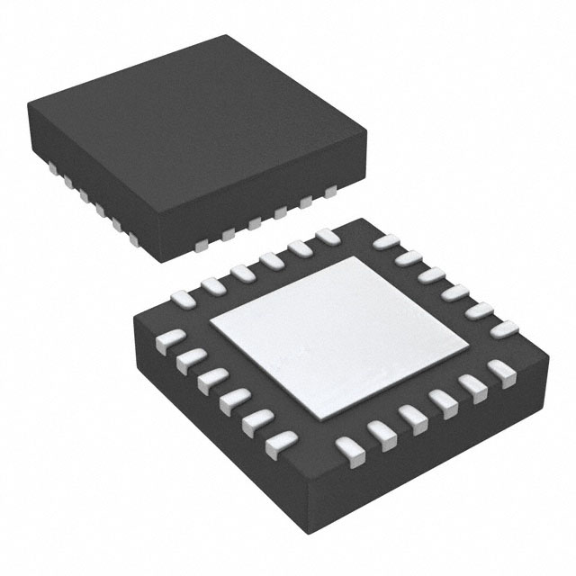


 工商网监
湘ICP备2023018690号
工商网监
湘ICP备2023018690号
