M, C, T
Vishay Dale
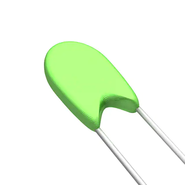
NTC Thermistors, Coated
FEATURES
• Small size - conformally coated
• Wide resistance range
• Available in 11 different R-T curves
DESCRIPTION
Models M, C, and T are conformally coated, leaded thermistors for standard PC board mounting or assembly in probes.
The coating is baked-on phenolic for durability and long-term stability. Models M and C have tinned solid copper leads.
Model T has solid nickel wires with Teflon® insulation to provide isolation when assembled in metal probes or housings.
DIMENSIONS in inches [millimeters]
1/4 NOM.
TINNED COPPER WIRE
TEFLON INSULATED NICKEL WIRE
BODY DIA.
MAX.
BODY DIA.
MAX.
1.5 [36.1] MIN.
CLEAN LEAD LENGTH
3 ± 0.25 [76.2 ± 6.4]
LD DIAMETER
WIRE SIZE
Type M
AWG 30: 0.0100 [0.254]
Type C
AWG 28: 0.0126 [0.320]
Type T
AWG 30: 0.0100 [0.254]
GLOBAL PART NUMBER INFORMATION
New Global Part Numbering: 01C2001FP (preferred part numbering format)
0
CURVE
01
02
03
04
07
08
09
12
13
14
17
1
C
2
0
GLOBAL MODEL
C
M
T
0
1
F
P
RESISTANCE VALUE
2001 = 2K
POINT MATCH TOLERANCE
F=±1%
J=±5%
K = ± 10 %
PACKAGING
F = Lead (Pb)-free, Bulk
P = Tin/Lead, Bulk
Historical Part Number example: 1C2001FP (will continue to be accepted)
01
C
2001
F
P
HISTORICAL CURVE
GLOBAL MODEL
RESISTANCE VALUE
TOLERANCE CODE
PACKAGING
New Global Part Numbering: 01C2001SPC3 (preferred part numbering format)
0
1
C
2
0
0
1
S
P
C
3
CURVE GLOBAL MODEL RESISTANCE VALUE CHARACTERISTICS
PACKAGING
01
C
2001 = 2K
S
F = Lead (Pb)-free, Bulk
02
M
P = Tin/Lead, Bulk
03
T
04
07
08
09
12
* See following pages for Tolerance
13
explanations and details.
14
17
Historical Part Number example: 1C2001SPC3 (will continue to be accepted)
01
C
2001
HISTORICAL CURVE GLOBAL MODEL
www.vishay.com
104
RESISTANCE VALUE
S
P
CURVE TRACK TOLERANCE*
A3
B3
C3
A2
B2
C2
A4
B4
A5
B5
C5
A8
B8
C8
C3
CHARACTERISTIC PACKAGING CURVE TRACK TOLERANCE
For technical questions, contact: thermistors1@vishay.com
Document Number: 33003
Revision: 22-Sep-04
�M, C, T
NTC Thermistors, Coated
Vishay Dale
SELECTION GUIDE FOR TYPE M, C, AND T THERMISTORS
R25
(Ω)
27
33
50
56
68
82
100
120
150
180
220
270
330
390
470
500
560
680
820
1K
1.2K
1.5K
1.8K
2.2K
2.7K
3.3K
3.9K
4.7K
5K
5.6K
6.8K
8.2K
10K
12K
15K
18K
22K
27K
33K
39K
47K
50K
56K
68K
82K
100K
120K
150K
180K
220K
270K
330K
390K
470K
500K
560K
680K
820K
1M
1
•
•
••
••
•••
•••
•••
•••
•••
•••
•••
•••
•••
•••
2
•
••
••
••
••
•••
•••
•••
•••
•••
•••
•••
•••
•••
Document Number: 33003
Revision: 22-Sep-04
3
4
CURVE NUMBER
7
8
9
12
14
17
•
••
•••
•••
•••
•••
•••
•••
•••
•••
•••
•
••
••
••
•••
•••
•••
•••
•••
•••
•••
•••
•••
MAXIMUM BODY DIAMETER
•
0.125 [3.2]
••
0.110 [2.8]
•••
0.095 [2.4]
DISSIPATION CONSTANT
2 - 3 mWatts/°C
THERMAL TIME CONSTANT
6 - 14 Seconds
Notes
•
•
••
••
••
••
•••
•••
•••
•••
•••
•••
•••
•••
•
•
••
••
••
•••
•••
•••
•••
•••
•••
•••
•••
•••
•
••
••
•••
•••
•••
•••
•••
•••
•••
•••
•••
•••
•
•
••
••
•••
•••
•••
•••
•••
•••
•••
•••
•
••
••
•••
•••
•••
•••
•••
•••
•••
•••
•••
1. Intermediate resistance values between
the standard value series are available.
Size would be the same as the color
grouping.
2. Other body diameter available. Bead
diameter increases as Res. decreases.
(Consult Factory)
3. Leaded series of thermistors includes
additional styles: (Consult Factory)
Type B:
Type F:
Type E:
Type D:
Type G:
Type H:
26AWG Lead, 0.0159 [0.40]
32AWG Lead, 0.008 [0.20]
24AWG Lead, 0.020 [0.51]
22AWG Lead, 0.025 [0.64]
20AWG Lead, 0.032 [0.81]
18AWG Lead, 0.040 [1.02]
•
••
••
•••
•••
•••
•••
•••
For technical questions, contact: thermistors1@vishay.com
www.vishay.com
105
�M, C, T
NTC Thermistors, Coated
Vishay Dale
TOLERANCES AVAILABLE FOR TYPE M, C AND T THERMISTORS
DESCRIPTION OF THERMISTOR TOLERANCES
The many applications of thermistors have mandated the need for two basic tolerance schemes for these products - Curve
Tracking and Point Match Thermistors. An example of the resistance tolerance at various temperatures for the two different
tolerancing methods is described in the following graph:
± 5 % POINT MATCH CURVE
10
9
TOLERANCE (± %)
8
7
25 °C
6
± 1 °C CURVE TRACK CURVE
5
4
A2
3
A8
A3
2
A4
1
150
130
140
120
110
100
90
80
70
60
50
30
20
10
0
- 10
- 20
- 30
- 40
- 50
40
A5
0
TEMPERATURE (°C)
CURVE TRACKING TOLERANCE
Thermistors are calibrated at the high temperature of the curve track range and then final tested at the low temperature of
the curve track range. This ensures that the thermistor will meet the specified temperature accuracy at every temperature within
the desired temperature range. Several temperature ranges are available and the accuracy of the thermistor may be ± 0.2 °C,
± 0.5 °C, and ± 1.0 °C. The Curve Tracking temperature ranges and their code designators are shown in Figure 1 and Table 1.
To specify, add the appropriate suffix from the following table to the part number.
Example: 1M1002-B3 = Curve 1, 10 kΩ at + 25 °C, curve tracking to ± 0.5 °C from 0 °C to + 70 °C
STANDARD ELECTRICAL SPECIFICATIONS FOR CURVE TRACKING THERMISTORS
TEMP.
RANGE
TOLERANCE
PART NO.
SUFFIX
0 °C to + 70 °C
- 20 °C to + 50 °C
0 °C to + 100 °C
25 °C to + 90 °C
0 °C to + 50 °C
± 1 °C ± 0.5 °C ± 0.2 °C ± 1 °C ± 0.5 °C ± 0.2 °C ± 1 °C ± 0.5 °C ± 0.2 °C ± 1 °C ± 0.5 °C ± 0.2 °C ± 1 °C ± 0.5 °C ± 0.2 °C
- A3
- B3
- C3
- A2
- B2
- C2
- A4
- B4
- C4
- A5
- B5
- C5
- A8
- B8
- C8
C
1
X
X
X
X
X
X
X
X
N/A
X
X
X
X
X
X
U
2
X
X
X
X
X
X
X
X
N/A
X
X
X
X
X
X
R
4
X
X
X
X
X
X
X
X
N/A
X
X
X
X
X
X
V
8
X
X
X
X
X
X
X
X
N/A
X
X
X
X
X
X
E
9
X
X
X
X
X
X
X
X
N/A
X
X
X
X
X
X
www.vishay.com
106
For technical questions, contact: thermistors1@vishay.com
Document Number: 33003
Revision: 22-Sep-04
�M, C, T
NTC Thermistors, Coated
Vishay Dale
POINT MATCH TOLERANCE
The standard leaded thermistors are calibrated and tested at 25 °C to a tolerance of ± 5 % or ± 10 %; however, tighter tolerance,
point matched thermistors are readily available as are special point match temperatures to fit your application.
Since these thermistors have only one controlled point of reference (the point match temperature), the resistance at other
temperatures is given by the "Resistance vs. Temperature Conversion Tables" for the appropriate material curve. The resistance
value at any temperature is the ratio factor times the resistance at 25 °C.
Example: 1M1002-5, + 70 °C resistance = (Resistance factor for curve 1 at 70 °C is 0.1990) x (10 000 W resistance at 25 °C)
= 1990 Ω.
The tolerance of the resistance at any temperature is described by Figure 2.
FIGURE 2
POINT MATCH TOLERANCES VS. TEMPERATURE
Point match resistance tolerances at temperatures other
than 25 ºC are not the same as the calibration temperature.
This difference is presented in Figure 2.
MAX. R vs. T
RESISTANCE
MIN. R vs. T
NOMINAL R vs. T
PIVOT POINT
(CALIBRATION TEMPERATURE)
The tolerance at any given temperature is the point match
tolerance + the MT ± % (Manufacturing Tolerance).
The MT ± % may be obtained from the R vs. T Conversion
tables and is added to the point match temperature, i.e.,
± 1 % Tol. at 25 ºC + ± 2.6 % at - 30 ºC for Curve 1 equals a
total tolerance of ± 3.6 % at - 30 ºC.
25 °C
TEMPERATURE
COMPUTER AIDS FOR THERMISTOR SELECTION
A spreadsheet is available for the Vishay Thermistor Materials that calculates Beta, Steinhart-Hart Equation Constants A, B, and
C, the resistance at any temperature based upon the Steinhart constants or Beta, the temperature equivalent of the resistance
reading, and resistance temperature coefficients.
This spread sheet will also calculate the total resistance tolerance of any point matched thermistor for temperatures in 10 ºC
increments, and the resistance tolerance at any temperature within the calibrated range of curve tracking thermistors. Please
contact factory if interested in this Excel™ spreadsheet.
Document Number: 33003
Revision: 22-Sep-04
For technical questions, contact: thermistors1@vishay.com
www.vishay.com
107
�Legal Disclaimer Notice
Vishay
Disclaimer
All product specifications and data are subject to change without notice.
Vishay Intertechnology, Inc., its affiliates, agents, and employees, and all persons acting on its or their behalf
(collectively, “Vishay”), disclaim any and all liability for any errors, inaccuracies or incompleteness contained herein
or in any other disclosure relating to any product.
Vishay disclaims any and all liability arising out of the use or application of any product described herein or of any
information provided herein to the maximum extent permitted by law. The product specifications do not expand or
otherwise modify Vishay’s terms and conditions of purchase, including but not limited to the warranty expressed
therein, which apply to these products.
No license, express or implied, by estoppel or otherwise, to any intellectual property rights is granted by this
document or by any conduct of Vishay.
The products shown herein are not designed for use in medical, life-saving, or life-sustaining applications unless
otherwise expressly indicated. Customers using or selling Vishay products not expressly indicated for use in such
applications do so entirely at their own risk and agree to fully indemnify Vishay for any damages arising or resulting
from such use or sale. Please contact authorized Vishay personnel to obtain written terms and conditions regarding
products designed for such applications.
Product names and markings noted herein may be trademarks of their respective owners.
Document Number: 91000
Revision: 18-Jul-08
www.vishay.com
1
�


 工商网监
湘ICP备2023018690号
工商网监
湘ICP备2023018690号
