HVCC Series
www.vishay.com
Vishay Roederstein
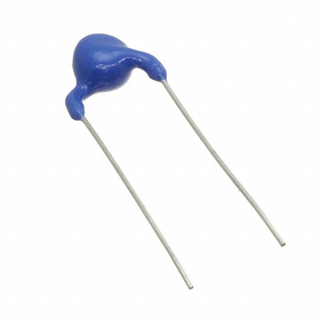
High Voltage Ceramic Capacitors
Radial-Leaded Singlelayer Disc
FEATURES
• Ceramic singlelayer DC disc / AC disc capacitor
• High reliability
• High capacitance values up to 2 nF
• Small sizes
• Low losses
• Radial leads
• Material categorization: for definitions of compliance
please see www.vishay.com/doc?99912
APPLICATIONS
• High voltage power supplies for x-ray sources and pulsed
lasers
LINKS TO ADDITIONAL RESOURCES
3D 3D
3D Models
• Baggage scanner
Related
Documents
Why It
Matters
Capabilities and
Custom Options
Did You
Know?
• Medical x-ray
• Industrial laser
• Airpurifier / ionizer
Infographics
DESIGN
QUICK REFERENCE DATA
DESCRIPTION
Ceramic class
Ceramic dielectric
Temperature coefficient of
capacitance
Voltage (Urated, DC)
VALUE
2
Y6P
± 10 % within -30 °C to +105 °C
10 000
15 000
20 000
Min. capacitance (pF)
100
100
100
Max. capacitance (pF)
Capacitance tolerance
Max. dissipation factor (%)
Min. insulation resistance (G)
Operating temperature (°C)
Mounting
2000
2000
1000
± 20 %, ± 10 %
1.5
200
-30 to +105
Radial
RATED VOLTAGE
Urated, AC = Urated, DC/2.8 at 50 Hz / 60 Hz
Urated, DC: 10 000 V Urated, AC: 3500 V
Urated, DC: 15 000 V Urated, AC: 5300 V
Urated, DC: 20 000 V Urated, AC: 7000 V
INSULATION RESISTANCE
Min. 200 000 M at 500 VDC / 60 s max.
The capacitors consist of a ceramic disc of which both sides
are silver-plated. Connection leads are made of tinned
copper clad steel wire having diameters of 0.026" (0.65 mm)
and 0.032" (0.80 mm).
The capacitors may be supplied with straight leads having
lead spacing of 0.37" (9.5 mm) and 0.49" (12.5 mm).
Coating is made of flame retardant epoxy resin in
accordance with “UL 94 V-0”.
CAPACITANCE RANGE
100 pF to 2000 pF
DIELECTRIC STRENGTH BETWEEN LEADS
1.5 x Urated, DC for maximum 60 s
Test voltage: customer re-test 1.35 x Urated, DC for maximum
60 s
Notes
• Considered as destructive test in insulation liquid
• Avoid flashover between wires and currents higher than 50 mA
CERAMIC DIELECTRIC
Y6P (± 10 % within -30 °C to +105 °C)
TOLERANCE ON CAPACITANCE
± 20 %, ± 10 %
DISSIPATION FACTOR
Max. 1.5 % at 1 kHz
OPERATING TEMPERATURE RANGE
-30 °C to +105 °C
Revision: 19-Jul-2021
Document Number: 23144
1
For technical questions, contact: slcap@vishay.com
THIS DOCUMENT IS SUBJECT TO CHANGE WITHOUT NOTICE. THE PRODUCTS DESCRIBED HEREIN AND THIS DOCUMENT
ARE SUBJECT TO SPECIFIC DISCLAIMERS, SET FORTH AT www.vishay.com/doc?91000
�HVCC Series
www.vishay.com
Vishay Roederstein
DIMENSIONS in millimeters (inches)
Thickness
Lead length
4.0 (0.15)
Diameter
ad
Le ace
p
s
Wire size
ORDERING INFORMATION, 10 kVDC
C
(pF)
TOL.
(%)
100
100
150
150
220
220
330
330
470
470
680
680
1000
1000
1500
1500
2000
± 20
± 10
± 20
± 10
± 20
± 10
± 20
± 10
± 20
± 10
± 20
± 10
± 20
± 10
± 20
± 10
± 20
MAXIMUM
DIAMETER
mm
8.0
8.0
8.0
8.0
9.0
9.0
10.0
10.0
12.0
12.0
13.0
13.0
15.0
15.0
17.0
17.0
19.0
INCH
0.31
0.31
0.31
0.31
0.35
0.35
0.39
0.39
0.47
0.47
0.51
0.51
0.59
0.59
0.67
0.67
0.75
MAXIMUM
THICKNESS
mm
9.0
9.0
8.0
8.0
8.0
8.0
8.0
8.0
8.0
8.0
7.5
7.5
7.5
7.5
7.5
7.5
8.0
INCH
0.35
0.35
0.31
0.31
0.31
0.31
0.31
0.31
0.31
0.31
0.30
0.30
0.30
0.30
0.30
0.30
0.31
LEAD SPACE
± 1 mm
(± 0.04")
mm
INCH
12.5
and
9.5
0.49
and
0.37
WIRE SIZE
± 0.05 mm
(± 0.002")
mm
INCH
0.80
and
0.65
0.032
and
0.026
LEAD LENGTH
± 5 mm
(± 0.2")
mm
INCH
30
1.18
ORDERING CODE
HVCC103Y6P101M###
HVCC103Y6P101K###
HVCC103Y6P151M###
HVCC103Y6P151K###
HVCC103Y6P221M###
HVCC103Y6P221K###
HVCC103Y6P331M###
HVCC103Y6P331K###
HVCC103Y6P471M###
HVCC103Y6P471K###
HVCC103Y6P681M###
HVCC103Y6P681K###
HVCC103Y6P102M###
HVCC103Y6P102K###
HVCC103Y6P152M###
HVCC103Y6P152K###
HVCC103Y6P202M###
ORDERING INFORMATION, 15 kVDC
C
(pF)
100
100
150
150
220
220
330
330
470
470
680
680
1000
1000
1500
1500
2000
TOL.
(%)
± 20
± 10
± 20
± 10
± 20
± 10
± 20
± 10
± 20
± 10
± 20
± 10
± 20
± 10
± 20
± 10
± 20
MAXIMUM
DIAMETER
mm
8.0
8.0
8.0
8.0
9.0
9.0
10.0
10.0
12.0
12.0
13.0
13.0
15.0
15.0
19.0
19.0
19.0
Revision: 19-Jul-2021
INCH
0.31
0.31
0.31
0.31
0.35
0.35
0.39
0.39
0.47
0.47
0.51
0.51
0.59
0.59
0.75
0.75
0.75
MAXIMUM
THICKNESS
mm
9.0
9.0
8.0
8.0
8.0
8.0
8.0
8.0
8.0
8.0
8.0
9.5
8.0
9.5
8.0
8.0
8.0
INCH
0.35
0.35
0.31
0.31
0.31
0.31
0.31
0.31
0.31
0.31
0.31
0.37
0.31
0.37
0.31
0.31
0.31
LEAD SPACE
± 1 mm
(± 0.04")
mm
INCH
12.5
and
9.5
0.49
and
0.37
WIRE SIZE
± 0.05 mm
(± 0.002")
mm
INCH
0.80
and
0.65
0.032
and
0.026
LEAD LENGTH
± 5 mm
(± 0.2")
mm
INCH
30
1.18
ORDERING CODE
HVCC153Y6P101M###
HVCC153Y6P101K###
HVCC153Y6P151M###
HVCC153Y6P151K###
HVCC153Y6P221M###
HVCC153Y6P221K###
HVCC153Y6P331M###
HVCC153Y6P331K###
HVCC153Y6P471M###
HVCC153Y6P471K###
HVCC153Y6P681M###
HVCC153Y6P681K###
HVCC153Y6P102M###
HVCC153Y6P102K###
HVCC153Y6P152M###
HVCC153Y6P152K###
HVCC153Y6P202M###
Document Number: 23144
2
For technical questions, contact: slcap@vishay.com
THIS DOCUMENT IS SUBJECT TO CHANGE WITHOUT NOTICE. THE PRODUCTS DESCRIBED HEREIN AND THIS DOCUMENT
ARE SUBJECT TO SPECIFIC DISCLAIMERS, SET FORTH AT www.vishay.com/doc?91000
�HVCC Series
www.vishay.com
Vishay Roederstein
ORDERING INFORMATION, 20 kVDC
C
(pF)
TOL.
(%)
100
100
150
150
220
220
330
330
470
470
680
680
1000
1000
± 20
± 10
± 20
± 10
± 20
± 10
± 20
± 10
± 20
± 10
± 20
± 10
± 20
± 10
MAXIMUM
DIAMETER
MAXIMUM
THICKNESS
LEAD SPACE
± 1 mm
(± 0.04")
mm
INCH
mm
INCH
mm
8.0
8.0
8.0
8.0
9.0
9.0
12.0
12.0
13.0
13.0
15.0
15.0
17.0
17.0
0.31
0.31
0.31
0.31
0.35
0.35
0.47
0.47
0.51
0.51
0.59
0.59
0.67
0.67
9.0
9.0
9.0
9.0
9.0
9.0
9.0
9.0
9.0
9.0
9.0
9.0
9.0
9.0
0.35
0.35
0.35
0.35
0.35
0.35
0.35
0.35
0.35
0.35
0.35
0.35
0.35
0.35
12.5
and
9.5
INCH
0.49
and
0.37
WIRE SIZE
± 0.05 mm
(± 0.002")
mm
0.80
and
0.65
LEAD LENGTH
± 5 mm
(± 0.2")
INCH
mm
0.032
and
0.026
30
ORDERING CODE
INCH
1.18
HVCC203Y6P101M###
HVCC203Y6P101K###
HVCC203Y6P151M###
HVCC203Y6P151K###
HVCC203Y6P221M###
HVCC203Y6P221K###
HVCC203Y6P331M###
HVCC203Y6P331K###
HVCC203Y6P471M###
HVCC203Y6P471K###
HVCC203Y6P681M###
HVCC203Y6P681K###
HVCC203Y6P102M###
HVCC203Y6P102K###
MARKING
SAMPLE < 470 pF
10 kV
15 kV
101M
101M
SAMPLE < 330 pF
SAMPLE
470 pF
SAMPLE
330 pF
20 kV
10 kV / 15 kV
20 kV
HVCC
101M
102M
15kV
YYWW
YYWW
YY - Year
WW - Week
Revision: 19-Jul-2021
Y6P / YY WW
YYWW
YY - Year
WW - Week
YY - Year
WW - Week
YY - Year
WW - Week
Document Number: 23144
3
For technical questions, contact: slcap@vishay.com
THIS DOCUMENT IS SUBJECT TO CHANGE WITHOUT NOTICE. THE PRODUCTS DESCRIBED HEREIN AND THIS DOCUMENT
ARE SUBJECT TO SPECIFIC DISCLAIMERS, SET FORTH AT www.vishay.com/doc?91000
�HVCC Series
www.vishay.com
Vishay Roederstein
ORDERING CODE
H
V
C
C
1
5
1
3
Y
6
2
P
1
0
3
2
M
4
E
5
A
X
6
7
1
2
3
4
5
6
7
SERIES
(HIGH VOLTAGE
CERAMIC CAPACITOR)
RATED VOLTAGE
TEMPERATURE
CHARACTERISTICS
CAPACITANCE
VALUE
CAPACITANCE
TOLERANCE
1st DIGIT:
LEAD TYPE /
LEAD SPACING /
GAUGE
PACKAGING
2nd DIGIT:
LEAD LENGTH
LEAD TYPE (position 6)
STANDARD TYPE
LEAD SPACING
(mm)
LEAD DIAMETER
(mm)
# GAUGE
MATERIAL
LEAD LENGTH
(mm)
Straight LL
9.5 ± 1.0
0.65
22
TCCSW
30 ± 5
Straight LL
12.5 ± 1.0
0.80
20
TCCSW
30 ± 5
CODE
LEAD TYPE
CA
EA
Notes
• 1th digit: lead type / lead spacing / gauge
2nd digit: A = long leads
• LL = long leads
• TCCSW = tinned copper clad steel wire
PACKAGING (position 7)
CODE
VERSION
X
Bulk
PERFORMANCE
NO.
PARAMETER
TEST CONDITIONS
SPECIFICATION
METHOD AND NOTES
1
Capacitance
Tol. K = ± 10 % at 1000 h
Tol. M = ± 20 % at 1000 h
2
Dissipation factor
DF / tan = max. 1.5 %
3
Insulation resistance
IR = min. 200 G in 60 s
t = 5 s
U = 500 VDC ± 10 VDC
NOTE: very high resistances are sensitive to the surrounding
area (may lead to unstable measurement values)
4
Dielectric strength
(between lead wires)
U1 = +1.35 x URDC/URAC max. 60 s
U2 = -1.35 x URDC/URAC max. 60 s
tU1 = tU2 = 60 s
Imax. = 50 mA
1. Apply +1.35 x URDC/URAC for max. 60 s
2. Unload part (Imax. = 50 mA)
3. Apply -1.35 x URDC for max. 60 s
4. Unload part (Imax. = 50 mA)
5. Avoid current spikes higher than 50 mA
5
Appearance and marking
No visible damage.
The marking shall be legible
Visual inspection
6
Dimensions
Dimensions are within specification
Measurement by caliper gauge
7.1
Temperature characteristics /
TCC
EIA code = Y6P
C/C0 = ± 10 %
Temp. range = -30 °C to 105 °C
7.2
Temperature characteristics /
TCDF
DF / tan = max. 1.5 %
Temp. range = -30 °C to 105 °C
Revision: 19-Jul-2021
Components are measured with a LCR-meter. Consider aging
of ceramic. Given tolerance is valid 1000 h ± 24 h after last
heating. Before and after that moment, aging offset has to be
considered.
(See general information for further instructions)
Measurement is done from cooler temperatures to hotter
temperatures in reasonable temperature steps. For
decreasing temperature run deaging effects must be
considered.
Document Number: 23144
4
For technical questions, contact: slcap@vishay.com
THIS DOCUMENT IS SUBJECT TO CHANGE WITHOUT NOTICE. THE PRODUCTS DESCRIBED HEREIN AND THIS DOCUMENT
ARE SUBJECT TO SPECIFIC DISCLAIMERS, SET FORTH AT www.vishay.com/doc?91000
�HVCC Series
www.vishay.com
Vishay Roederstein
PERFORMANCE
NO.
PARAMETER
TEST CONDITIONS
SPECIFICATION
METHOD AND NOTES
1. Connect both lead wires together
2. Dip component headfirst into a bath with oil and
metal balls (fig.)
3. Apply voltage between lead wires and metal balls
8
Dielectric strength of
body insulation
U = 5000 VDC
t = 60 s
Metal
foil
About 3 mm to 4 mm
Metal balls
U
(V)
90 %
9
Pulse test
tr = 1.2 μs
tf = 50 μs
U = 1.25 x URDC
n = 50 x single polarity
Rise time:
ts = 1.2 µs ± 30 %
100 %
Half value time:
tr = 50 µs ± 20 %
50 %
30 %
Over swing:
ü
很抱歉,暂时无法提供与“HVCC153Y6P151MEAX”相匹配的价格&库存,您可以联系我们找货
免费人工找货- 国内价格
- 1+21.92058
- 10+16.95525
- 25+16.78554
- 50+15.59757
- 100+11.06789
- 500+10.75997


 工商网监
湘ICP备2023018690号
工商网监
湘ICP备2023018690号
