Datasheet Values Refer to PCN-OPT-1224-2022
TSSP4P38
www.vishay.com
Vishay Semiconductors
IR Mid Range Proximity Sensors
DESCRIPTION
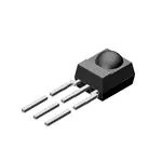
The TSSP4P38 is a compact infrared detector module
for proximity sensing applications. It receives 38 kHz
modulated signals and has a peak sensitivity of 940 nm.
The length of the detector’s output pulse varies in proportion
to the amount of light reflected from the object being
detected.
FEATURES
•
•
•
•
•
•
•
•
•
23196
LINKS TO ADDITIONAL RESOURCES
Product Page
Marking
Packages
Holders
Up to 2 m for proximity sensing
Uses modulated bursts at 38 kHz
Photo detector and preamplifier in one package
Low supply current
Shielding against EMI
Visible light is suppressed by IR filter
Insensitive to supply voltage ripple and noise
Supply voltage: 2.0 V to 5.5 V
Material categorization: for definitions of
compliance please see www.vishay.com/doc?99912
Bends and Cuts
APPLICATIONS
• Object approach detection for activation of displays and
user consoles, signaling of alarms, etc.
• Simple gesture controls
• Differentiation of car arrival, static, car departure in
parking lots
• Reflective sensors for toilet flush
• Navigational sensor for robotics
DESIGN SUPPORT TOOLS
• 3D models
• Window size calculator
BLOCK DIAGRAM
16833_5
3
33 kΩ
VS
1
Input
AGC
Band
pass
Demodulator
OUT
2
PIN
Rev. 2.3, 16-Aug-2022
1
Control circuit
GND
Document Number: 82474
THIS DOCUMENT IS SUBJECT TO CHANGE WITHOUT NOTICE. THE PRODUCTS DESCRIBED HEREIN AND THIS DOCUMENT
ARE SUBJECT TO SPECIFIC DISCLAIMERS, SET FORTH AT www.vishay.com/doc?91000
�Datasheet Values Refer to PCN-OPT-1224-2022
TSSP4P38
www.vishay.com
Vishay Semiconductors
MECHANICAL DATA
PROXIMITY SENSING
Pinning
1 = OUT, 2 = GND, 3 = VS
+3 V
IR emitter
Envelope
signal
38 kHz
+3 V
Out to
μC
1
IR detector
2
3
23198
ORDERING CODE
TSSP4P38 - 2160 pieces in tubes
PARTS TABLE
Carrier frequency
38 kHz
TSSP4P38
Package
Mold
Pinning
1 = OUT, 2 = GND, 3 = VS
Dimensions (mm)
6.0 W x 6.95 H x 5.6 D
Mounting
Leaded
Application
Special options
Proximity sensors
• Narrow optical filter: www.vishay.com/doc?81590
• Wide optical filter: www.vishay.com/doc?82726
ABSOLUTE MAXIMUM RATINGS
PARAMETER
SYMBOL
VALUE
Supply voltage (pin 3)
TEST CONDITION
VS
-0.3 to +6
V
Supply current (pin 3)
IS
5
mA
V
Output voltage (pin 1)
Voltage at output to supply
Output current (pin 1)
Junction temperature
UNIT
VO
-0.3 to 5.5
VS - VO
-0.3 to (VS + 0.3)
V
IO
5
mA
Tj
100
°C
Storage temperature range
Tstg
-25 to +85
°C
Operating temperature range
Tamb
-25 to +85
°C
Tamb ≤ 85 °C
Ptot
10
mW
t ≤ 10 s, 1 mm from case
Tsd
260
°C
Power consumption
Soldering temperature
Note
• Stresses beyond those listed under “Absolute Maximum Ratings” may cause permanent damage to the device. This is a stress rating only
and functional operation of the device at these or any other conditions beyond those indicated in the operational sections of this specification
is not implied. Exposure to absolute maximum rating conditions for extended periods may affect the device reliability
Rev. 2.3, 16-Aug-2022
2
Document Number: 82474
THIS DOCUMENT IS SUBJECT TO CHANGE WITHOUT NOTICE. THE PRODUCTS DESCRIBED HEREIN AND THIS DOCUMENT
ARE SUBJECT TO SPECIFIC DISCLAIMERS, SET FORTH AT www.vishay.com/doc?91000
�Datasheet Values Refer to PCN-OPT-1224-2022
TSSP4P38
www.vishay.com
Vishay Semiconductors
ELECTRICAL AND OPTICAL CHARACTERISTICS (Tamb = 25 °C, unless otherwise specified)
PARAMETER
TEST CONDITION
SYMBOL
MIN.
TYP.
MAX.
UNIT
Ee = 0, VS = 3.3 V
ISD
0.25
0.35
0.45
mA
Ev = 40 klx, sunlight
ISH
-
0.45
-
mA
VS
2.0
-
5.5
V
Receiving distance
Direct line of sight,
test signal see Fig. 1,
IR diode TSAL6200, IF = 50 mA
d
-
26
-
m
Output voltage low
IOSL = 0.5 mA, Ee = 0.7 mW/m2,
test signal see Fig. 1
VOSL
-
-
100
mV
Minimum irradiance
Pulse width tolerance:
tpi - 5/fo < tpo < tpi + 5/fo,
test signal see Fig. 1
Ee min.
-
0.1
0.2
mW/m2
Maximum irradiance
Pulse width tolerance:
tpi - 5/fo < tpo < tpi + 5/fo,
test signal see Fig. 1
Ee max.
30
-
-
W/m2
Angle of half receiving distance
ϕ1/2
-
± 45
-
deg
Supply current
Supply voltage
Directivity
TYPICAL CHARACTERISTICS (Tamb = 25 °C, unless otherwise specified)
Optical Test Signal
(IR diode TSAL6200, 30 pulses, f = f0, T = 10 ms)
1.0
0.9
E e min./Ee - Rel. Responsivity
Ee
t
tpi (1)
(1)
T
tpi ≥ 16/f0
Output Signal
(2)
11/f0 < td < 17/f0
VO
(3)
VOH
16110-17
tpi - 5/f0 < tpo < tpi + 5/f0
0.8
0.7
0.6
0.5
0.4
0.3
0.2
f = f0 ± 5 %
Δf (3 dB) = f0/10
0.1
0.0
25
VOL
td (2)
tpo (3)
30
t
Fig. 1 - Output Active Low
1000
0.6
0.5
0.4
100
0.3
λ = 950 nm,
optical test signal, Fig. 1
0.0
0.1
10
1000
10000
Correlation with ambient light sources:
10 W/m2 = 1.4 klx (std. ilum. A, T = 2855 K)
10 W/m2 = 8.2 klx (daylight, T = 5900 K)
3
Wavelength of ambient
illumination: λ = 950 nm
2
100
1
0
0.01
10
100 000
1000
1st line
2nd line
2nd line
Ee min. - Threshold Irradiance (mW/m2)
Input burst length
1st line
2nd line
2nd line
tpo - Output Pulse Width (ms)
0.8
0.1
10
0.1
1
10
Ee - Irradiance (mW/m2)
Ee - Ambient DC Irradiance (W/m2)
Fig. 2 - Pulse Length and Sensitivity in Dark Ambient
Fig. 4 - Sensitivity in Bright Ambient
Rev. 2.3, 16-Aug-2022
50
Axis Title
Output pulse width
0.2
45
4
10000
0.7
40
Fig. 3 - Frequency Dependence of Responsivity
Axis Title
1.0
0.9
35
f/f0 - Relative Frequency
3
100
Document Number: 82474
THIS DOCUMENT IS SUBJECT TO CHANGE WITHOUT NOTICE. THE PRODUCTS DESCRIBED HEREIN AND THIS DOCUMENT
ARE SUBJECT TO SPECIFIC DISCLAIMERS, SET FORTH AT www.vishay.com/doc?91000
�Datasheet Values Refer to PCN-OPT-1224-2022
TSSP4P38
www.vishay.com
Vishay Semiconductors
Axis Title
Axis Title
10000
0.7
0.6
1000
0.5
f = f0
f = 30 kHz
0.4
f = 10 kHz
f = 100 Hz
0.3
100
0.2
0.1
1
10
0.8
0.7
100
1000
0.6
0.5
0.4
100
0.3
0.2
0.1
10
1000
0
10000
0.9
1st line
2nd line
2nd line
S(λ)rel. - Relative Spectral Sensitivity
1.0
1st line
2nd line
2nd line
Ee min. - Threshold Irradiance (mW/m2)
0.8
10
1150
0
750
∆VS RMS - AC Voltage on DC Supply Voltage (mV)
850
1050
λ - Wavelength (nm)
23180
Fig. 5 - Sensitivity vs. Supply Voltage Disturbances
950
Fig. 8 - Relative Spectral Sensitivity vs. Wavelength
Axis Title
200
180
1.0
1000
160
1st line
2nd line
2nd line
tpo - Output Pulse Width (ms)
220
1.1
10000
dark
1 W/m² ambient DC light
10 W/m² ambient DC light
Burst length = 200 ms,
burst rep. time 1s
Relative Response Distance
240
140
120
100
100
80
60
40
0.9
0.8
0.7
0.6
0.5
0.4
0.3
Directivity Characteristic of a
Reflective Sensor using
VSLB3940 and TSSP4P38
0.2
0.1
20
0.0
0
10
0.1
1
10
-90 -70 -50 -30 -10
100
10
30
50
70
90
Angle (°)
Ee - Irradiance (mW/m2)
Fig. 6 - Max. Output Pulse Width vs. Irradiance
Fig. 9 - Angle Characteristic
Axis Title
700
trepeat min. (ms)
0.4
1000
0.3
1st line
2nd line
2nd line
Ee min. - Threshold Irradiance (mW/m2)
800
10000
0.5
0.2
600
500
400
300
100
200
0.1
100
0
10
0
-30
-10
10
30
50
70
0
90
20
40
60
80
100 120 140 160 180
tpi (ms)
Tamb - Ambient Temperature (°C)
Fig. 7 - Sensitivity vs. Ambient Temperature
Rev. 2.3, 16-Aug-2022
Fig. 10 - Max. Rate of Bursts
4
Document Number: 82474
THIS DOCUMENT IS SUBJECT TO CHANGE WITHOUT NOTICE. THE PRODUCTS DESCRIBED HEREIN AND THIS DOCUMENT
ARE SUBJECT TO SPECIFIC DISCLAIMERS, SET FORTH AT www.vishay.com/doc?91000
�Datasheet Values Refer to PCN-OPT-1224-2022
TSSP4P38
www.vishay.com
Vishay Semiconductors
140
7
120
6
100
5
dmax./dmin.
tpo (ms)
Emitter: VSLB3940
80
60
4
3
IF = 100 mA
2
40
20
1
IF = 10 mA
IF = 50 mA
IF = 30 mA
0
0
0.0
0.4
0.8
1.2
1.6
2.0
10 20 30 40 50 60 70 80 90 100 110 120
2.4
tpi (ms)
Response Distance (m)
Fig. 11 - tpo vs. Distance Kodak Gray Card Plus 15 %
Fig. 12 - Dynamic Range of Sensor vs. tpi
The typical application of the TSSP4P38 is a reflective sensor with analog information contained in its output. The sensor
evaluates the time required by the AGC to suppress a quasi continuous signal. The time required to suppress a continuous
signal is longer when the signal is strong than when the signal is weak. The result is an output pulse length which corresponds
to the distance of an object from the sensor. This kind of analog information can be evaluated by a microcontroller. The absolute
amount of reflected light depends on the infrared reflectivity of the object and is not evaluated. Only changes in the amount of
reflected light, and therefore changes in the pulse width can be evaluated with accuracy.
Example of a signal pattern:
trepeat = 500 ms
tpi = 120 ms, 38 kHz
Optical signal
Response of the
TSSP4P38
(strong reflection)
Response of the
TSSP4P38
(weak reflection)
Example for a sensor hardware:
IR detector
IR emitter
Separation to avoid
crosstalk by stray light inside
the housing
There should be no common window in front of the emitter and detector in order to avoid crosstalk by guided light through the
window.
The logarithmic characteristic of the AGC in the TSSP4P38 results in an almost linear relationship between distance and pulse
width. Ambient light has also some impact to the pulse width of this kind of sensor, making the pulse shorter.
Rev. 2.3, 16-Aug-2022
5
Document Number: 82474
THIS DOCUMENT IS SUBJECT TO CHANGE WITHOUT NOTICE. THE PRODUCTS DESCRIBED HEREIN AND THIS DOCUMENT
ARE SUBJECT TO SPECIFIC DISCLAIMERS, SET FORTH AT www.vishay.com/doc?91000
�Datasheet Values Refer to PCN-OPT-1224-2022
TSSP4P38
www.vishay.com
Vishay Semiconductors
PACKAGE DIMENSIONS in millimeters
3.9
1
30.5
± 0.5
(5.55)
8.25
6.95
5.3
6
1
0.85 max.
0.89
OUT
GND
VS
0.5 max.
2.54 nom.
1.3
0.7 max.
4.1
2.54 nom.
5.6
Marking area
Not indicated tolerances ± 0.2
technical drawings
according to DIN
specifications
Drawing-No.: 6.550-5169.11-4
R 2.5
Issue: 13; 17.12.08
16003
Rev. 2.3, 16-Aug-2022
6
Document Number: 82474
THIS DOCUMENT IS SUBJECT TO CHANGE WITHOUT NOTICE. THE PRODUCTS DESCRIBED HEREIN AND THIS DOCUMENT
ARE SUBJECT TO SPECIFIC DISCLAIMERS, SET FORTH AT www.vishay.com/doc?91000
�Legal Disclaimer Notice
www.vishay.com
Vishay
Disclaimer
ALL PRODUCT, PRODUCT SPECIFICATIONS AND DATA ARE SUBJECT TO CHANGE WITHOUT NOTICE TO IMPROVE
RELIABILITY, FUNCTION OR DESIGN OR OTHERWISE.
Vishay Intertechnology, Inc., its affiliates, agents, and employees, and all persons acting on its or their behalf (collectively,
“Vishay”), disclaim any and all liability for any errors, inaccuracies or incompleteness contained in any datasheet or in any other
disclosure relating to any product.
Vishay makes no warranty, representation or guarantee regarding the suitability of the products for any particular purpose or
the continuing production of any product. To the maximum extent permitted by applicable law, Vishay disclaims (i) any and all
liability arising out of the application or use of any product, (ii) any and all liability, including without limitation special,
consequential or incidental damages, and (iii) any and all implied warranties, including warranties of fitness for particular
purpose, non-infringement and merchantability.
Statements regarding the suitability of products for certain types of applications are based on Vishay's knowledge of typical
requirements that are often placed on Vishay products in generic applications. Such statements are not binding statements
about the suitability of products for a particular application. It is the customer's responsibility to validate that a particular product
with the properties described in the product specification is suitable for use in a particular application. Parameters provided in
datasheets and / or specifications may vary in different applications and performance may vary over time. All operating
parameters, including typical parameters, must be validated for each customer application by the customer's technical experts.
Product specifications do not expand or otherwise modify Vishay's terms and conditions of purchase, including but not limited
to the warranty expressed therein.
Hyperlinks included in this datasheet may direct users to third-party websites. These links are provided as a convenience and
for informational purposes only. Inclusion of these hyperlinks does not constitute an endorsement or an approval by Vishay of
any of the products, services or opinions of the corporation, organization or individual associated with the third-party website.
Vishay disclaims any and all liability and bears no responsibility for the accuracy, legality or content of the third-party website
or for that of subsequent links.
Except as expressly indicated in writing, Vishay products are not designed for use in medical, life-saving, or life-sustaining
applications or for any other application in which the failure of the Vishay product could result in personal injury or death.
Customers using or selling Vishay products not expressly indicated for use in such applications do so at their own risk. Please
contact authorized Vishay personnel to obtain written terms and conditions regarding products designed for such applications.
No license, express or implied, by estoppel or otherwise, to any intellectual property rights is granted by this document or by
any conduct of Vishay. Product names and markings noted herein may be trademarks of their respective owners.
© 2022 VISHAY INTERTECHNOLOGY, INC. ALL RIGHTS RESERVED
Revision: 01-Jan-2022
1
Document Number: 91000
�


 工商网监
湘ICP备2023018690号
工商网监
湘ICP备2023018690号

