WKO Series
www.vishay.com
Vishay Roederstein
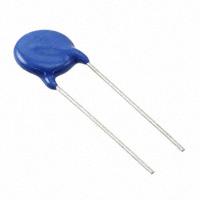
EMI Suppression Capacitor, Ceramic Disc,
Class X1, 440 VAC, Class Y2, 300 VAC
FEATURES
• Complying with IEC 60384-14
• High reliability
• Wide range of different leadstyles
• Singlelayer AC disc safety capacitors
• Material categorization: for definitions of
compliance please see www.vishay.com/doc?99912
APPLICATIONS
• X1, Y2 according to IEC 60384-14.4
• Line-to-line filtering (Class X)
LINKS TO ADDITIONAL RESOURCES
• Line-to-ground filtering (Class Y)
3D 3D
• EMI / RFI suppression and filtering
• Primary and secondary coupling (SMPS)
3D Models
DESIGN
QUICK REFERENCE DATA
DESCRIPTION
The capacitors consist of ceramic disc both sides of which
are silver plated. Connection leads are made of tinned
copper having diameters of 0.6 mm or 0.8 mm.
VALUE
Ceramic Class
1
Ceramic Dielectric
Voltage (VAC)
2
N750
N750
Y5S,
Y5T,
Y5U
Y5S,
Y5T,
Y5U
The capacitors may be supplied with straight or kinked
leads having a lead spacing of 7.5 mm or 12.5 mm.
300
440
300
440
Coating is made of blue colored flame retardant epoxy resin
in accordance with UL 94 V-0.
Min. Capacitance (pF)
33
68
Max. Capacitance (pF)
47
4700
Mounting
Radial
OPERATING TEMPERATURE RANGE
-40 °C to +125 °C
(1)
CAPACITANCE RANGE
33 pF to 4.7 nF
TOLERANCE ON CAPACITANCE
± 10 %, ± 20 %
Note
(1) For explanation about the difference of operating temperature
range and temperature characteristic of capacitance please see
www.vishay.com/doc?48299
RATED VOLTAGE
TEMPERATURE CHARACTERISTICS
• Y2: 300 VAC, 50 Hz (IEC 60384-14)
300 VAC, 50 Hz / 60 Hz (US/UL/CSA 60384-14)
Class 1: N750
Class 2: Y5S, Y5T, Y5U
SECTIONAL SPECIFICATIONS
Climatic category (according to EN 60058-1)
Class 1: 40 / 125 / 21
Class 2: 40 / 125 / 21
APPROVALS
• X1: 440 VAC, 50 Hz (IEC 60384-14)
440 VAC, 50 Hz / 60 Hz (US/UL/CSA 60384-14)
TEST VOLTAGE
• 2600 VAC, 50 Hz, 2 s
Component test (100 %)
• 2600 VAC, 50 Hz, 60 s Random sampling test (destructive)
• 2600 VAC, 50 Hz, 60 s Voltage proof of coating (destructive)
INSULATION RESISTANCE AT 500 VDC
≥ 6000 MΩ (60 s)
IEC 60384-14
DISSIPATION FACTOR
UL 60384-14
Class 1: max. 0.5 % (1 MHz)
CSA E60384-14
Class 2: max. 2.5 % (1 kHz)
Revision: 28-Jan-2022
Document Number: 22204
1
For technical questions, contact: slcap@vishay.com
THIS DOCUMENT IS SUBJECT TO CHANGE WITHOUT NOTICE. THE PRODUCTS DESCRIBED HEREIN AND THIS DOCUMENT
ARE SUBJECT TO SPECIFIC DISCLAIMERS, SET FORTH AT www.vishay.com/doc?91000
�WKO Series
www.vishay.com
Vishay Roederstein
DIMENSIONS in millimeters
Smax.
3.0 max.
Dmax.
V
F
30 - 3
or 10 ± 1
Ø d ± 0.05
TECHNICAL DATA
CAPACITANCE
TOLERANCE
BODY
DIAMETER
DMAX. (mm)
BODY
THICKNESS
SMAX. (mm)
LEAD
SPACING (2)
F (mm)
± 1 mm
LEAD
DIAMETER (2)
d (mm)
± 0.05 mm
WIDTH (2)
V (mm)
± 0.5 mm
PART NUMBER
MISSING DIGITS
SEE ORDERING
CODE BELOW
33
47
± 10 %,
± 20 %
8.0
5.0
7.5
0.6
1.6
WKO330#CP###KR
WKO470#CP###KR
68
100
± 10 %,
± 20 %
8.0
5.0
7.5
0.6
1.9
WKO680#CP###KR
WKO101#CP###KR
150
220
330
± 10 %,
± 20 %
8.0
5.0
7.5
0.6
1.9
WKO151#CP###KR
WKO221#CP###KR
WKO331#CP###KR
0.6
2.0
± 10 %,
± 20 %
8.0
9.0
10.0
12.0
13.0
15.0
16.0
18.0
0.8
1.6
CAPACITANCE (1)
C (pF)
N750
Y5S
Y5T
Y5U
470
680
1000
1500
2200
3300
3900
4700
5.0
7.5
12.5
Notes
(1) Capacitance values from 1 nF to 4.7 nF: the alternative usage of VKO series is recommended for new application
(2) Standard lead configuration, other lead spacing and diameter available on request
WKO471#CP###KR
WKO681#CP###KR
WKO102#CP###KR
WKO152#CP###KR
WKO222#CP###KR
WKO332#CP###KR
WKO392#CP###KR
WKO472#CP###KR
ORDERING CODE
#
###
Example
7th digit
10th to 12th digit
WKO
Series
Capacitance tolerance
Lead configuration
222
M
Capacitance
Tolerance code
value
± 10 % = K, ± 20 % = M
See “General Information” www.vishay.com/doc?22001
CP
CJ0
K
R
Lead
Voltage code
Internal code
RoHS compliant
configuration
MARKING
WKO
440~X1
300~Y2
33p M
WKO 33 pF to 1.0 nF
Revision: 28-Jan-2022
WKO 2n2 M
IEC 384-14
440 300 250~
X1 Y2
WKO 1.5 nF to 4.7 nF
Document Number: 22204
2
For technical questions, contact: slcap@vishay.com
THIS DOCUMENT IS SUBJECT TO CHANGE WITHOUT NOTICE. THE PRODUCTS DESCRIBED HEREIN AND THIS DOCUMENT
ARE SUBJECT TO SPECIFIC DISCLAIMERS, SET FORTH AT www.vishay.com/doc?91000
�WKO Series
www.vishay.com
Vishay Roederstein
APPROVALS
IEC 60384-14 - Safety tests
This approval together with CB test certificate substitutes all national approvals.
CB Certificate (www.vishay.com/doc?22217)
Y2-capacitor: CB test certificate:
US-26157-UL
33 pF to 4.7 nF
300 VAC
X1-capacitor: CB test certificate:
US-26157-UL
33 pF to 4.7 nF
440 VAC
Y2-capacitor: VDE marks approval:
136820
33 pF to 4.7 nF
300 VAC
X1-capacitor: VDE marks approval:
136820
33 pF to 4.7 nF
440 VAC
Minimum thickness of insulation: 0.4 mm
VDE (www.vishay.com/doc?22219)
DIN EN 60384-14 (VDE 0565-1-1)
Minimum thickness of insulation: 0.4 mm
Underwriters Laboratories Inc. / Canadian Standards Association (www.vishay.com/doc?22218)
Y2-capacitor: UL-test certificate:
E183844
33 pF to 4.7 nF
300 VAC
X1-capacitor: UL-test certificate:
E183844
33 pF to 4.7 nF
440 VAC
UL 60384-14, CSA E60384-14
Minimum thickness of insulation: 0.4 mm
IMPEDANCE VS. FREQUENCY (typical)
3000
10
Z (Ω)
I (μA)
AC CURRENT VS. VOLTAGE (typical)
4.7 nF
2000
1
4700 pF
3900 pF
3300 pF
2200 pF
1500 pF
1000 pF
680 pF
470 pF
330 pF
220 pF
150 pF
100 pF
68 pF
47 pF
33 pF
3.3 nF
2.2 nF
1000
0.1
1 nF
0
0.01
0
500
1000
1500
2000
1
2500
10
100
UR (V~)
1000
f (MHz)
STORAGE
The capacitors must not be stored in a corrosive atmosphere, where sulphide or chloride gas, acid, alkali or salt are present.
Exposure of the components to moisture, should be avoided. The solderability of the leads is not affected by storage of up to
24 months (temperature +10 °C to +35 °C, relative humidity up to 60 %). Class 2 ceramic dielectric capacitors are also subject
to aging, see www.vishay.com/doc?22001.
SOLDERING
SOLDERING SPECIFICATIONS
Soldering test for capacitors with wire leads: (according to IEC 60068-2-20, solder bath method)
Soldering temperature
Soldering duration
Distance from component body
Revision: 28-Jan-2022
SOLDERABILITY
RESISTANCE TO SOLDERING HEAT
235 °C ± 5 °C
260 °C ± 5 °C
2 s ± 0.5 s
10 s ± 1 s
≥ 2 mm
≥ 5 mm
Document Number: 22204
3
For technical questions, contact: slcap@vishay.com
THIS DOCUMENT IS SUBJECT TO CHANGE WITHOUT NOTICE. THE PRODUCTS DESCRIBED HEREIN AND THIS DOCUMENT
ARE SUBJECT TO SPECIFIC DISCLAIMERS, SET FORTH AT www.vishay.com/doc?91000
�WKO Series
www.vishay.com
Vishay Roederstein
SOLDERING RECOMMENDATIONS
Soldering of the component should be achieved using a Sn60/40 type or a silver-bearing Sn62/36/2Ag type solder. Ceramic
capacitors are very sensitive to rapid changes in temperature (thermal shock) therefore the solder heat resistance specification
(see Soldering Specifications table) should not be exceeded. Subjecting the capacitor to excessive heating may result in thermal
shocks that can crack the ceramic body. Similarly, excessive heating can cause the internal solder junction to melt.
CLEANING
The components should be cleaned immediately following the soldering operation with vapor degreasers.
SOLVENT RESISTANCE
The coating and marking of the capacitors are resistant to the following test method: IEC 60068-2-45 (method XA).
MOUNTING
If a defined product stop is required for mounting on a PCB, a mechanically formed product stop (kinked or inline wire) or a
mounting tool should be used.
We do not recommend modifying the lead terminals, e.g. bending or cropping. This action could break the coating or crack the
ceramic insert. If however, the lead must be modified in any way, we recommend support of the lead with a clamping fixture
next to the coating.
OPERATING VOLTAGE
In case the voltage is applied to the circuit, starting as well as stopping, may generate irregular voltage for a transit period
because of resonance or switching. Be sure to use a capacitor with a rated voltage range that includes these irregular voltages.
OPERATING TEMPERATURE AND SELF-GENERATED HEAT
Keep the surface temperature of a capacitor below the upper limit of its rated operating temperature range. Be sure to take into
account the heat generated by the capacitor itself. When the capacitor is used in a high frequency, pulse, or similar application,
it may have self-generated heat due to dielectric dissipation.
Temperature increase due to self-generated heating should not exceed 20 °C while operating at an atmosphere temperature of
25 °C.
When measuring, the surface temperature, make sure that the capacitor is not affected by radiant, conductive and convective
heat by its surroundings. Excessive heat may lead to thermo-mechanical deterioration of the capacitor's characteristics and
reliability.
RELATED DOCUMENTS
General Information
www.vishay.com/doc?22001
CB Test Certificate
www.vishay.com/doc?22217
VDE Marks Approval
www.vishay.com/doc?22219
UL Test Certificate
www.vishay.com/doc?22218
Revision: 28-Jan-2022
Document Number: 22204
4
For technical questions, contact: slcap@vishay.com
THIS DOCUMENT IS SUBJECT TO CHANGE WITHOUT NOTICE. THE PRODUCTS DESCRIBED HEREIN AND THIS DOCUMENT
ARE SUBJECT TO SPECIFIC DISCLAIMERS, SET FORTH AT www.vishay.com/doc?91000
�Legal Disclaimer Notice
www.vishay.com
Vishay
Disclaimer
ALL PRODUCT, PRODUCT SPECIFICATIONS AND DATA ARE SUBJECT TO CHANGE WITHOUT NOTICE TO IMPROVE
RELIABILITY, FUNCTION OR DESIGN OR OTHERWISE.
Vishay Intertechnology, Inc., its affiliates, agents, and employees, and all persons acting on its or their behalf (collectively,
“Vishay”), disclaim any and all liability for any errors, inaccuracies or incompleteness contained in any datasheet or in any other
disclosure relating to any product.
Vishay makes no warranty, representation or guarantee regarding the suitability of the products for any particular purpose or
the continuing production of any product. To the maximum extent permitted by applicable law, Vishay disclaims (i) any and all
liability arising out of the application or use of any product, (ii) any and all liability, including without limitation special,
consequential or incidental damages, and (iii) any and all implied warranties, including warranties of fitness for particular
purpose, non-infringement and merchantability.
Statements regarding the suitability of products for certain types of applications are based on Vishay's knowledge of typical
requirements that are often placed on Vishay products in generic applications. Such statements are not binding statements
about the suitability of products for a particular application. It is the customer's responsibility to validate that a particular product
with the properties described in the product specification is suitable for use in a particular application. Parameters provided in
datasheets and / or specifications may vary in different applications and performance may vary over time. All operating
parameters, including typical parameters, must be validated for each customer application by the customer's technical experts.
Product specifications do not expand or otherwise modify Vishay's terms and conditions of purchase, including but not limited
to the warranty expressed therein.
Hyperlinks included in this datasheet may direct users to third-party websites. These links are provided as a convenience and
for informational purposes only. Inclusion of these hyperlinks does not constitute an endorsement or an approval by Vishay of
any of the products, services or opinions of the corporation, organization or individual associated with the third-party website.
Vishay disclaims any and all liability and bears no responsibility for the accuracy, legality or content of the third-party website
or for that of subsequent links.
Except as expressly indicated in writing, Vishay products are not designed for use in medical, life-saving, or life-sustaining
applications or for any other application in which the failure of the Vishay product could result in personal injury or death.
Customers using or selling Vishay products not expressly indicated for use in such applications do so at their own risk. Please
contact authorized Vishay personnel to obtain written terms and conditions regarding products designed for such applications.
No license, express or implied, by estoppel or otherwise, to any intellectual property rights is granted by this document or by
any conduct of Vishay. Product names and markings noted herein may be trademarks of their respective owners.
© 2023 VISHAY INTERTECHNOLOGY, INC. ALL RIGHTS RESERVED
Revision: 01-Jan-2023
1
Document Number: 91000
�


 工商网监
湘ICP备2023018690号
工商网监
湘ICP备2023018690号
