6N138,6N139
TOSHIBA Photocoupler GaAℓAs Ired & Photo IC
6N138, 6N139
Current Loop Driver. Low Input Current Line Receiver. CMOS Logic Interface.
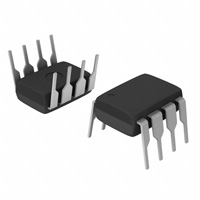
The TOSHIBA 6N138 and 6N139 consists of a GaAℓAs infrared emitting diode coupled with a split-Darlington output configuration. A high speed GaAℓAs Ired manufactured with an unique LPE junction, has the virtue of fast rise and fall time at low drive current. • • Isolation voltage: 2500Vrms (min.) Current transfer ratio : 6N138 − 300% (min.) (IF=1.6mA) : 6N139 − 400% (min.) (IF=0.5mA) • Switching time: 6N138 − tPHL=10μs (max.) − tPLH=35μs (max.) 6N139 − tPHL=1μs (max.) − tPLH=7μs (max.) • UL recognized: UL1577, file no. E67349 TOSHIBA Weight: 0.54 g 11−10C4 Unit in mm
Pin Configuration (top view)
1 : N .C . 2 : Anode 3 : C a th o d e 2 7 4 : N .C . 5 : G nd 3 6 6 : O u tp u t 7 : O u tp u t B a s e 8 : VCC 4 5
1
8
Schematic
VCC 8 2
+
IF IC C IO 6 VO
VF
-
3
IB VB
7
5 GND
1
2007-10-01
�6N138,6N139
Absolute Maximum Ratings (*) (Ta = 0°C to + 70°C)
Characteristic Forward current Pulse forward current LED Total pulse forward current Reverse voltage Diode power dissipation Output current Detector Emitter−base reverse voltage Supply voltage Output voltage Output power dissipation Operating temperature range Storage temperature range Lead solder temperature (10s)
(*4)
Symbol (Note 1) IF IFP IFP
(*1) (*2)
Rating 20 40 1 5 35 60 0.5 −0.5 to 18 −0.5 to 18 100 0 to 70 −55 to 125 260 2500 3540
Unit mA mA A V mW mA V V V mW °C °C °C Vrms Vdc
VR (Note 2) (Note 3) PD IO VEB VCC VO (Note 4)
(*3)
(*3)
PO Topr Tstg Tsol BVS
(**)
Isolation voltage (1min., R.H.≤ 60%)
Note: Using continuously under heavy loads (e.g. the application of high temperature/current/voltage and the significant change in temperature, etc.) may cause this product to decrease in the reliability significantly even if the operating conditions (i.e. operating temperature/current/voltage, etc.) are within the absolute maximum ratings. Please design the appropriate reliability upon reviewing the Toshiba Semiconductor Reliability Handbook (“Handling Precautions”/“Derating Concept and Methods”) and individual reliability data (i.e. reliability test report and estimated failure rate, etc). (*) JEDEC registered data (**) Not registered JEDEC (*1) 50% duty cycle, 1ms pulse width (*2) Pulse width 1μs, 300pps (*3) 6N138… −0.5 to 7V (*4) 1.6mm below seating plane
2
2007-10-01
�6N138,6N139
Electrical Characteristics Over Recommended Temperature (Ta = 0°C to 70°C, unless otherwise noted)
Characteristic Symbol Test Condition IF=0.5mA, VO=0.4V VCC=4.5V CTR(*) IF=1.6mA, VO=0.4V VCC=4.5V IF=1.6mA, IO=6.4mA VCC=4.5V Logic low output voltage 6N139 (Note 6) VOL IF=5mA, IO=15mA VCC=4.5V IF=12mA, IO=24mA VCC=4.5V IF=1.6mA, IO=4.8mA VCC=4.5V IOH(*) ICCL ICCH VF(*) BVR(*) IF=0mA, VO=VCC=18V IF=0mA, VO=VCC=7V IF=1.6mA, VO=Open VCC=5V IF=0mA, VO=Open, VCC=5V IF=1.6mA, Ta=25°C IR=10μA, Ta=25°C Min. 400 500 300 ⎯ ⎯ ⎯ ⎯ ⎯ ⎯ ⎯ ⎯ ⎯ 5 ⎯ ⎯ (Note 7), (Note 7) ⎯ ⎯ (*5)Typ. 800 900 600 0.1 0.1 0.2 0.1 0.05 0.05 0.2 10 1.65 ⎯ −1.9 60 10
12
Max. ⎯ ⎯ ⎯ 0.4 0.4
Unit
Current transfer ratio
6N139 (Note 5, 6) 6N138
%
V 0.4 0.4 100 250 ⎯ ⎯ 1.7 ⎯ ⎯ ⎯ ⎯ ⎯ μA mA nA V V mV / °C pF Ω pF
6N138 Logic high output current 6N139 (Note 6) 6N138 (Note 6) Logic high supply current (Note 6) Input forward voltage Input reverse breakdown voltage Temperature coefficient of forward voltage Input capacitance Resistance (input−output) Capacitance (input−output)
Logic low supply current
ΔVF / ΔTa IF=1.6mA CIN RI−O CI−O f=1MHz, VF=0 VI−O=500V R.H.≤ 60% f=1MHz
0.6
(**) JEDEC registered data. (*5) All typicals at Ta=25°C and VCC=5V, unless otherwise noted.
3
2007-10-01
�6N138,6N139
Switching Specifications (Ta=25°C, VCC=5V, unless otherwise specified)
Characteristic Propagation delay time to logic low at output (Note 6, 8) 6N139 6N138 6N139 6N138 CMH 2 Symbol Test Circuit Test Condition IF=0.5mA, RL=4.7kΩ tpHL(*) 1 IF=12mA, RL=270Ω IF=1.6mA, RL=2.2kΩ IF=0.5mA, RL=4.7kΩ tpLH(*) 1 IF=12mA, RL=270Ω IF=1.6mA, RL=2.2kΩ IF=0mA, RL=2.2kΩ VCM=400Vp−p IF=1.6mA RL=2.2kΩ VCM=400Vp−p Min. ⎯ ⎯ ⎯ ⎯ ⎯ ⎯ ⎯ Typ. 5 0.2 1 5 1 4 500 Max. 25 1 10 60 7 35 ⎯ V / μs μs μs Unit
Propagation delay time to logic high at output (Note 6, 8) Common mode transient immunity at logic high level output Common mode transient immunity at logic low level output
(Note 9)
(Note 9)
CML
2
⎯
−500
⎯
V / μs
(*)JEDEC registered data. (Note 1): (Note 2): (Note 3): (Note 4): (Note 5): (Note 6): (Note 7): (Note 8): (Note 9): Derate linearly above 50°C free−air temperature at a rate of 0.4mA / °C Derate linearly above 50°C free−air temperature at a rate of 0.7mW / °C Derate linearly above 25°C free−air temperature at a rate of 0.7mA / °C Derate linearly above 25°C free−air temperature at a rate of 2.0mW / °C DC CURRENT TRANSFER RATIO is defined as the ratio of output collector current, IO, to the forward LED input current, IF, times 100%. Pin 7 open. Device considered a two−terminal device: Pins 1, 2, 3, and 4 shorted together and Pins 5, 6, 7 and 8 shorted together. Use of a resistor between pin 5 and 7 will decrease gain and delay time. Common mode transient immunity in logic high level is the maximum tolerable (positive) dvCM / dt on the leading edge of the common mode pulse, VCM, to assure that the output will remain in a logic high state (i.e., VO > 2.0V). Common mode transient immunity in Logic Low level is the maximum tolerable (negative) dvCM / dt on the trailing edge of the common mode pulse signal, VCM, to assure that the output will remain in a logic low state (i.e., VO < 0.8V).
4
2007-10-01
�6N138,6N139
Test Circuit 1.
IF 0 VO (Saturated Response) 1.5V tpHL VO (NonSaturated Response) 10% 90% tr 90% 10% tf 1.5V tpLH 5V 5V Pulse gen. Zo = 50Ω tf = 5ns 10% Duty cycle 1 / f < 100μs 100Ω IF MonitorF
IF
1 2 3 4
8 7 6 5 RL
+5V
VOL
VO CL (*)
(*)CL is approximately 15pF which includes probe and stray wiring capacitance.
Test Circuit 2.
tr, tf = 0.64μs 90% tr VO Swith at A : IF = 0mA VOL VO Swith at B : IF = 1.6mA Pulse gen tf 0V B 5V VFF A IF 1 2 3 4 8 7 6 5 RCC RL VO +5V
400V VCM 10%
+
VCM
-
5
2007-10-01
�6N138,6N139
RESTRICTIONS ON PRODUCT USE
• The information contained herein is subject to change without notice.
20070701-EN
• TOSHIBA is continually working to improve the quality and reliability of its products. Nevertheless, semiconductor devices in general can malfunction or fail due to their inherent electrical sensitivity and vulnerability to physical stress. It is the responsibility of the buyer, when utilizing TOSHIBA products, to comply with the standards of safety in making a safe design for the entire system, and to avoid situations in which a malfunction or failure of such TOSHIBA products could cause loss of human life, bodily injury or damage to property. In developing your designs, please ensure that TOSHIBA products are used within specified operating ranges as set forth in the most recent TOSHIBA products specifications. Also, please keep in mind the precautions and conditions set forth in the “Handling Guide for Semiconductor Devices,” or “TOSHIBA Semiconductor Reliability Handbook” etc. • The TOSHIBA products listed in this document are intended for usage in general electronics applications (computer, personal equipment, office equipment, measuring equipment, industrial robotics, domestic appliances, etc.).These TOSHIBA products are neither intended nor warranted for usage in equipment that requires extraordinarily high quality and/or reliability or a malfunction or failure of which may cause loss of human life or bodily injury (“Unintended Usage”). Unintended Usage include atomic energy control instruments, airplane or spaceship instruments, transportation instruments, traffic signal instruments, combustion control instruments, medical instruments, all types of safety devices, etc.. Unintended Usage of TOSHIBA products listed in his document shall be made at the customer’s own risk. • The products described in this document shall not be used or embedded to any downstream products of which manufacture, use and/or sale are prohibited under any applicable laws and regulations. • The information contained herein is presented only as a guide for the applications of our products. No responsibility is assumed by TOSHIBA for any infringements of patents or other rights of the third parties which may result from its use. No license is granted by implication or otherwise under any patents or other rights of TOSHIBA or the third parties. • GaAs(Gallium Arsenide) is used in this product. The dust or vapor is harmful to the human body. Do not break, cut, crush or dissolve chemically. • Please contact your sales representative for product-by-product details in this document regarding RoHS compatibility. Please use these products in this document in compliance with all applicable laws and regulations that regulate the inclusion or use of controlled substances. Toshiba assumes no liability for damage or losses occurring as a result of noncompliance with applicable laws and regulations.
6
2007-10-01
�


 工商网监
湘ICP备2023018690号
工商网监
湘ICP备2023018690号
