MODULE FOR STEPPER MOTORS
MODULE
Hardware Version V1.4
HARDWARE MANUAL
+
+
TMCM-1021
1-Axis Stepper
Controller / Driver
24V DC
up-to 0.7A RMS / 1.4A RMS
RS485 Interface
sensOstep™ Encoder
+
UNIQUE FEATURES:
TRINAMIC Motion Control GmbH & Co. KG
Hamburg, Germany
www.trinamic.com
+
�TMCM-1021 V1.4 Hardware Manual (Rev. 1.04 / 2018-JAN-22)
Table of Contents
1
2
3
Features........................................................................................................................................................................... 3
Order Codes ................................................................................................................................................................... 5
Mechanical and Electrical Interfacing ..................................................................................................................... 6
3.1
Size of Board ........................................................................................................................................................ 6
3.1.1 Board mounting considerations ............................................................................................................... 6
3.2
Connectors ............................................................................................................................................................. 7
3.2.1 Power, Communication and I/O Connector .......................................................................................... 8
3.2.2 Motor Connector .......................................................................................................................................... 13
4
Motor driver current .................................................................................................................................................. 14
5
Reset to Factory Defaults ......................................................................................................................................... 16
6
On-board LED............................................................................................................................................................... 16
7
Operational Ratings ................................................................................................................................................... 17
8
Functional Description .............................................................................................................................................. 19
9
Life Support Policy ..................................................................................................................................................... 20
10 Revision History .......................................................................................................................................................... 21
10.1 Document Revision ........................................................................................................................................... 21
10.2 Hardware Revisions .......................................................................................................................................... 21
11 References .................................................................................................................................................................... 22
www.trinamic.com
2
�TMCM-1021 V1.4 Hardware Manual (Rev. 1.04 / 2018-JAN-22)
3
1 Features
The TMCM-1021 is a single axis controller/driver module for 2-phase bipolar stepper motors with state of the
art feature set. It is highly integrated, offers a convenient handling and can be used in many decentralized
applications. The module can be mounted on the back of NEMA11 (28mm flange size) and has been designed
for coil currents up to 0.7A RMS (low current range, programmable) or 1.4A RMS (high current range,
programmable, new additional range since hardware version 1.4) and 24V DC supply voltage. With its high
energy efficiency from TRINAMIC’s coolStep™ technology cost for power consumption is kept down. The TMCL™
firmware supports remote control (direct mode) and standalone operation (with TMCL program being executed
on the TMCM-1021 itself).
MAIN CHARACTERISTICS
Highlights
Motion profile calculation in real-time
On the fly alteration of motor parameters (e.g. position, velocity, acceleration)
High performance microcontroller for overall system control and serial communication protocol handling
For position movement applications, where larger motors do not fit and higher torques are not required
Bipolar stepper motor driver
Up to 256 microsteps per full step
High-efficient operation, low power dissipation
Dynamic current control
Integrated protection
stallGuard2 feature for stall detection
coolStep feature for reduced power consumption and heat dissipation
Encoder
sensOstep magnetic encoder (max. 1024 increments per rotation) e.g. for step-loss detection under all
operating conditions and positioning supervision
Interfaces
Up to 4 multi-purpose inputs (2 shared with general purpose outputs)
2 general purpose outputs
RS485 2-wire communication interface
Software
TMCL: standalone operation or remote controlled operation,
program memory (non volatile) for up to 876 TMCL commands, and
PC-based application development software TMCL-IDE available for free.
Electrical and mechanical data
Supply voltage: +24V DC nominal (9… 28V DC max.)
Motor current: up to 0.7A RMS (low current range, programmable) or 1.4A RMS (high current range,
programmable, new additional range since hardware version 1.4)
Please refer to separate TMCL Firmware Manual, also.
www.trinamic.com
�TMCM-1021 V1.4 Hardware Manual (Rev. 1.04 / 2018-JAN-22)
4
TRINAMICS UNIQUE FEATURES – EASY TO USE WITH TMCL
stallGuard2™
stallGuard2 is a high-precision sensorless load measurement using the back EMF on the coils.
It can be used for stall detection as well as other uses at loads below those which stall the
motor. The stallGuard2 measurement value changes linearly over a wide range of load,
velocity, and current settings. At maximum motor load, the value goes to zero or near to zero.
This is the most energy-efficient point of operation for the motor.
Load
[Nm]
stallGuard2
Initial stallGuard2
(SG) value: 100%
Max. load
stallGuard2 (SG) value: 0
Maximum load reached.
Motor close to stall.
Motor stalls
Figure 1.1 stallGuard2 load measurement SG as a function of load
coolStep™
coolStep is a load-adaptive automatic current scaling based on the load measurement via
stallGuard2 adapting the required current to the load. Energy consumption can be reduced by
as much as 75%. coolStep allows substantial energy savings, especially for motors which see
varying loads or operate at a high duty cycle. Because a stepper motor application needs to
work with a torque reserve of 30% to 50%, even a constant-load application allows significant
energy savings because coolStep automatically enables torque reserve when required.
Reducing power consumption keeps the system cooler, increases motor life, and allows
reducing cost.
0,9
Efficiency with coolStep
0,8
Efficiency with 50% torque reserve
0,7
0,6
0,5
Efficiency
0,4
0,3
0,2
0,1
0
0
50
100
150
200
250
300
350
Velocity [RPM]
Figure 1.2 Energy efficiency example with coolStep
www.trinamic.com
�TMCM-1021 V1.4 Hardware Manual (Rev. 1.04 / 2018-JAN-22)
5
2 Order Codes
Order code
TMCM-1021
Size of unit
Description
Single axis bipolar stepper motor controller/driver 28mm x 28mm
electronics with integrated encoder electronics
Table 2.1 Order codes
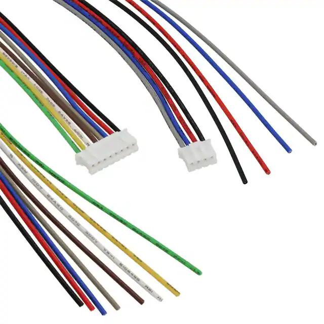
A cable loom set is available for this module:
Order code
TMCM-1021-CABLE
Description
Cable loom for TMCM-1021
1x cable loom for power, communication and
(cable length approx. 200mm)
1x cable loom for motor connector (cable length ca. 200mm)
Table 2.2 Cable loom order code
www.trinamic.com
I/O
connector
�TMCM-1021 V1.4 Hardware Manual (Rev. 1.04 / 2018-JAN-22)
6
3 Mechanical and Electrical Interfacing
3.1 Size of Board
The board with the controller/driver electronics has an overall size of 28mm x 28mm in order to fit on the
back side of a NEMA11 (28mm flange size) stepper motor. The printed circuit board outline is marked green
in the following figure:
28mm
27mm
25.5mm
R 2mm
PCB outline
25.5mm
27mm
28mm
28mm x 28mm
Motor backbell
R 1.3mm
R 2.5mm
Figure 3.1 Board dimensions and position of mounting holes
Maximum board height (without mating connectors and cable looms) is about 10mm (approx. 6mm above
printed circuit board level).
3.1.1 Board mounting considerations
The board offers two mounting holes for M2.5 screws (both holes with 2.6mm diameter). Both mounting holes
are isolated. Nevertheless, it is highly recommended to electrically connect any metal screws used for mounting
to supply ground (either directly or via resistor) in order to prevent any electrostatic discharge (ESD) across
the isolation barrier. This is especially recommended in case the board is mounted to the backside of a motor.
Since hardware version 1.4 a second high current range for motor currents up-to 1.4A RMS is available. This
makes it possible to support NEMA11 motors with typical standard coil currents up-to 0.7A RMS using the low
current range and with the same hardware also NEMA17 bipolar stepper motors with coil currents up-to 1.4A
RMS using the high current range.
Example for setup with TMCM-1021_V14 mounted to back side of NEMA17 motor (with sensOstep™ encoder):
Figure 3.2: TMCM-1021 V14 mounted to back side of NEMA17 bipolar stepper motor
www.trinamic.com
�TMCM-1021 V1.4 Hardware Manual (Rev. 1.04 / 2018-JAN-22)
7
3.2 Connectors
The TMCM-1021 has two connectors, an 8-pin power, communication and I/O (input/output) connector and a
4-pin motor connector (used to connect the attached motor).
Power / communication / I/Os
1
8
4
1
Motor
Figure 3.3 TMCM-1021 connectors
Overview of connector and mating connector types:
Label
Connector type
Mating connector types
Connector housing CVIlux: CI01085000-A
Contacts CVIlux: CI01T011PE0-A
Power,
communication
and I/O
CI0108P1VK0-LF
CVIlux CI01 series, 8pins, 2mm
pitch
or
Connector housing JST: PHR-8
Contacts JST: SPH-002T-P0.5S
Wire: 0.22mm2
Connector housing CVIlux: CI01045000-A
Contacts CVIlux: CI01T011PE0-A
Motor
CI0104P1VK0-LF
CVIlux CI01 series, 4 pins, 2mm
pitch
or
Connector housing JST: PHR-4
Contacts JST: SPH-002T-P0.5S
Wire: 0.22mm2
Table 3.1 Connectors and mating connectors, contacts and applicable wire
www.trinamic.com
�TMCM-1021 V1.4 Hardware Manual (Rev. 1.04 / 2018-JAN-22)
8
3.2.1 Power, Communication and I/O Connector
An 8-pin, 2mm pitch single row connector is used for power supply, RS485 serial communication and
additional multi-purpose inputs and outputs.
Pin
1
2
3
4
Label
GND
VDD
RS485+
RS485-
Direction
Power (GND)
Power (Supply)
Bidirectional
Bidirectional
5
IN_0
Input
6
IN_1
Input
7
OUT_0 / IN_2 Output / Input
8
OUT_1 / IN_3 Output / Input
Description
GND
VDD, typ. +24V (+9V…+28V max.)
RS485 interface, diff. signal (non-inverting)
RS485 interface, diff. signal (inverting)
General purpose digital input,
+24V compatible, internal 20k pull-down resistor
Alternate function 1: Step input,
+24V compatible, internal 20k pull-down resistor.
Please note: the bandwidth of the low-pass (noise rejection) filter at
the input is 16kHz (-3dB) which will limit the upper step frequency
Alternate function 2: Left stop switch,
+24V compatible, internal 20k pull-down resistor
General purpose digital input,
+24V compatible, internal 20k pull-down resistor
Alternate function 1: Direction input,
+24V compatible, internal 20k pull-down resistor
Please note: the bandwidth of the low-pass (noise rejection) filter at
the input is 16kHz (-3dB)
Alternate function 2: Right stop switch,
+24V compatible, internal 20k pull-down resistor
Open drain output with freewheeling diode (max. 100mA)
Please note: there is a 20k pull-down resistor of the input connected
in parallel
Alternate function 1: general purpose digital input,
+24V compatible, internal 20k pull-down resistor
Alternate function 2:
home switch, +24V compatible, internal 20k pull-down resistor
Open drain output with freewheeling diode (max. 100mA)
Please note: there is a 20k pull-down resistor of the input connected
in parallel
Alternate function 1:
digital input, +24V compatible, internal 20k pull-down resistor
Alternate function 2:
analog input, 0..6.6V range, +24V survival, internal 20k pull-down
resistor
Table 3.2 8pin power, communication and I/O connector
www.trinamic.com
�TMCM-1021 V1.4 Hardware Manual (Rev. 1.04 / 2018-JAN-22)
9
3.2.1.1 Power supply
For proper operation care has to be taken with regard to power supply concept and design. Due to space
restrictions the TMCM-1021 includes just about 20µF/35V (V1.2) resp. 30µF/35V (V1.4) of supply filter capacitors.
These are ceramic capacitors which have been selected for high reliability and long life time. The module
includes a 24V suppressor diode for over-voltage protection.
Please take the following measures into account in order to avoid serious damage of the device:
Add external power supply capacitors!
It is recommended to connect an electrolytic capacitor of significant size (e.g. 470µF/35V) to
the power supply lines next to the TMCM-1021!
Rule of thumb for size of electrolytic capacitor: c = 1000
μF
A
× ISUPPLY
In addition to power stabilization (buffer) and filtering this added capacitor will also reduce
any voltage spikes which might otherwise occur from a combination of high inductance
power supply wires and the ceramic capacitors. In addition it will limit slew-rate of power
supply voltage at the module. The low ESR of ceramic-only filter capacitors may cause stability
problems with some switching power supplies.
Keep the power supply voltage below the upper limit of 28V!
Otherwise the driver electronics will seriously be damaged! Especially, when the selected
operating voltage is near the upper limit a regulated power supply is highly recommended.
Please see also chapter 7, operating values.
There is no reverse polarity protection!
The module will short any reversed supply voltage due to internal diodes of the driver
transistors.
3.2.1.2 RS485
For remote control and communication with a host system the TMCM-1021 provides a two wire RS485 bus
interface. For proper operation the following items should be taken into account when setting up an RS485
network:
1.
BUS STRUCTURE:
The network topology should follow a bus structure as closely as possible. That is, the connection
between each node and the bus itself should be as short as possible. Basically, it should be short
compared to the length of the bus.
Host
c:>
Slave
Slave
Slave
node
1
node
n-1
node
n
}
termination
resistor
(120 Ohm)
RS485
termination
resistor
(120 Ohm)
keep distance as
short as possible
Figure 3.4: Bus structure
2.
BUS TERMINATION:
Especially for longer busses and/or multiple nodes connected to the bus and/or high communication
speeds, the bus should be properly terminated at both ends. The TMCM-1021 does not integrate any
termination resistor. Therefore, 120 Ohm termination resistors at both ends of the bus have to be
added externally.
www.trinamic.com
�TMCM-1021 V1.4 Hardware Manual (Rev. 1.04 / 2018-JAN-22)
10
3.
NUMBER OF NODES:
The RS485 electrical interface standard (EIA-485) allows up to 32 nodes to be connected to a single
bus. The bus transceivers used on the TMCM-1021 units (hardware V1.2: SN65HVD3082ED, since
hardware V1.4: SN65HVD1781D) have a significantly reduced bus load and allow a maximum of 255
units to be connected to a single RS485 bus using TMCL firmware. Please note: usually it cannot be
expected to get reliable communication with the maximum number of nodes connected to one bus
and maximum supported communication speed at the same time. Instead, a compromise has to be
found between bus cable length, communication speed and number of nodes.
4.
COMMUNICATION SPEED:
The maximum RS485 communication speed supported by the TMCM-1021 is 115200 bit/s (FW version
1.29 with TMCM-1021 hardware version 1.2 and 1.4). Factory default is 9600 bit/s. Please see separate
TMCM-1021 TMCL firmware manual for information regarding other possible communication speeds
below 115200 bit/s.
5.
NO FLOATING BUS LINES:
Avoid floating bus lines while neither the host/master nor one of the slaves along the bus line is
transmitting data (all bus nodes switched to receive mode). Floating bus lines may lead to
communication errors. In order to ensure valid signals on the bus it is recommended to use a resistor
network connecting both bus lines to well defined logic levels.
There are actually two options which can be recommended:
Add resistor (Bias) network on one side of the bus, only (120R termination resistor still at both ends):
Slave
Slave
node
n- 1
node
n
+5V
pull-up (680R)
RS485+ / RS485A
termination
resistor
(220R)
termination
resistor
(120R)
RS485- / RS485B
pull-down (680R)
GND
Figure 3.5: Bus lines with resistor (Bias) network on one side, only
Or add resistor (Bias) network at both ends of the bus (like Profibus™ termination):
+5V
pull-up (390R)
Slave
Slave
node
n- 1
node
n
pull-up (390R)
RS485+ / RS485A
termination
resistor
(220R)
termination
resistor
(220R)
RS485- / RS485B
pull-down (390R)
GND
Figure 3.6: Bus lines with resistor (Bias) network at both ends
www.trinamic.com
+5V
pull-down (390R)
GND
�TMCM-1021 V1.4 Hardware Manual (Rev. 1.04 / 2018-JAN-22)
11
Certain RS485 interface converters available for PCs already include these additional resistors (e.g. USB2-485 with bias network at one end of the bus).
3.2.1.3 Digital Inputs IN_0 and IN_1
The eight pin connector of the TMCM-1021 provides four general purpose inputs IN_0, IN_1, IN_2 and IN_3.
The first two inputs have dedicated connector pins while the other two share pins with two general purpose
outputs.
All four inputs are protected using voltage resistor dividers together with limiting diodes against voltages
below 0V (GND) and above +3.3V DC. Input circuit of the first two inputs IN_0 and IN_1 is shown below:
IN_0,
IN_1
+3.3V
10k
microcontroller
and stepper
motor driver
10k
1nF
GND
GND
GND
Figure 3.7 General purpose inputs IN_0 and IN_1
The two inputs have alternate functions depending on configuration in software. The following functions are
available:
Label
(connector pin)
IN_0 (5)
Default Function
Alternate function 1
Alternate function 2
Digital input
+24V compatible,
internal 20k pulldown resistor
Left stop switch
+24V
compatible,
internal 20k pulldown resistor
IN_1 (6)
Digital input
+24V compatible,
internal 20k pulldown resistor
Step signal input
(connected to stepper motor driver step
input)
+24V compatible, internal 20k pull-down
resistor.
Please note: the bandwidth of the low-pass
RC (10k / 1nF) filter at the input is 16kHz (3dB) which will limit the upper step
frequency
Direction signal input
(connected to stepper motor driver
direction input)
+24V compatible, internal 20k pull-down
resistor.
Please note: the bandwidth of the low-pass
RC (10k / 1nF) filter at the input is 16kHz (3dB)
Right stop switch
+24V
compatible,
internal 20k pulldown resistor
Table 3.3 Multipurpose inputs / alternate functions
All four inputs are connected to the on-board processor and can be used as general purpose digital inputs.
Using the alternate function 1 of IN_0 and IN_1 it is possible to control the on-board stepper motor driver
with the help of an external stepper motor controller using step and direction signals (Please see separate
TMCL firmware manual / axis parameter 254 for more details how to enable this mode). For the step and
www.trinamic.com
�TMCM-1021 V1.4 Hardware Manual (Rev. 1.04 / 2018-JAN-22)
12
direction signals the signal levels are the same as for the general purpose digital inputs. Please note that the
low-pass filter (for noise rejection) at the inputs offers a bandwidth of 16kHz (-3dB).
IN_3 can be used as analog input, also. A 12bit analog to digital converter integrated in the microcontroller
will convert any analog input voltage between 0 and +6.6V to a digital value between 0 and 4095 then.
3.2.1.4 Inputs IN_2, IN_3, Digital Outputs OUT_0, OUT_1
The eight pin connector of the TMCM-1021 provides two general purpose outputs. These two outputs are opendrain outputs and can sink up to 100mA each. Both outputs OUT_0 and OUT_1 share pins with two of the four
inputs (IN_2 resp. IN_3).
The inputs are protected using voltage resistor dividers together with limiting diodes against voltages below
0V (GND) and above +3.3V DC. The circuit of the two outputs and the two inputs connected in parallel to the
inputs is shown below:
VDD
OUT_0 / IN_2
OUT_1 / IN_3
+3.3V
10k
microcontroller
10k
1nF
GND
GND
GND
microcontroller
since V1.4
1k
GND
GND
Figure 3.8 General purpose outputs OUT_0, OUT_1 and inputs IN_2, IN_3 connected in parallel
The outputs of the N-channel MOSFET transistors (Open-Drain) are connected to freewheeling diodes each for
protection against voltage spikes especially from inductive loads (relais etc.). Please take into account the 20k
(2x 10k in series) resistance to ground (transistor not active) of the input voltage divider (figure 4.8) when
designing the external “load” circuit.
Since hardware version 1.4 the gate inputs of the MOSFETs are pulled-low during power-up and while the
processor might be still in reset / output pins not initialized. This way, the outputs will not briefly switch on
at power-up.
The two outputs OUT_0 / OUT_1 and inputs IN_2 / IN_3 have alternate functions depending on configuration
in software:
Label
(connector pin)
OUT_0 / IN_2 (7)
www.trinamic.com
Default Function
Alternate function 1
Alternate function 2
Open drain output with
freewheeling diode (max.
100mA)
Please note: there is a 20k
pull-down resistor of the
input connected in parallel
Alternate function 1: general
purpose digital input,
+24V compatible, internal
20k pull-down resistor
Alternate function 2:
home
switch,
+24V
compatible, internal 20k
pull-down resistor
�TMCM-1021 V1.4 Hardware Manual (Rev. 1.04 / 2018-JAN-22)
13
Label
(connector pin)
OUT_1 / IN_3 (8)
Default Function
Alternate function 1
Alternate function 2
Open drain output with
freewheeling diode (max.
100mA)
Please note: there is a 20k
pull-down resistor of the
input connected in parallel
Alternate function 1:
digital
input,
+24V
compatible, internal 20k
pull-down resistor
Alternate function 2:
analog input, 0..6.6V range,
+24V survival, internal 20k
pull-down resistor
Table 3.4 Multipurpose outputs / inputs / alternate functions
Do not apply any voltage above supply voltage to inputs IN_2 and IN_3. Due to the
freewheeling diodes of the outputs connected in parallel they will be shorted to power supply
input voltage.
For hardware version 1.2: Do not connect either IN_2 or IN_3 directly to a low resistance
supply voltage (e.g. directly to any power supply voltage). As the output transistors connected
in parallel might briefly switch-on during power-up they might be damaged / destroyed if the
current through the transistors to ground exceeds 100mA.
3.2.2 Motor Connector
A 4-pin, 2mm pitch single row connector is used for connecting the four motor wires to the electronics.
Pin
1
2
3
4
Label
OB2
OB1
OA2
OA1
Direction
Output
Output
Output
Output
Description
Pin
Pin
Pin
Pin
2
1
2
1
of
of
of
of
motor
motor
motor
motor
coil
coil
coil
coil
B
B
A
A
Table 3.4 Motor connector
Do not connect or disconnect motor during operation!
Motor cable and motor inductivity might lead to voltage spikes when the motor is
disconnected / connected while energized. These voltage spikes might exceed voltage limits
of the driver MOSFETs and might permanently damage them. Therefore, always disconnect
power supply before connecting / disconnecting the motor.
For hardware version 1.4: please note the additional high current range for motor
currents up-to 1.4A RMS!
Setting motor current too high might lead to excessive power dissipation inside the motor,
overheating and even permanent damage of the motor. Therefore, make sure the motor
current is properly set. Also with hardware version 1.2 the low current range is set as default.
Example for connecting a motor.
black
www.trinamic.com
Description
Motor coil B
Motor coil B
Motor coil A
Motor coil A
M
A
pin
pin
pin
pin
2
1
2
1
green
blue
Coil
BB
AA
B
Motor connector pin Cable colour
1
Blue
2
Red
3
Green
4
Black
QSH2818 Motor
red
TMCM-1021
�TMCM-1021 V1.4 Hardware Manual (Rev. 1.04 / 2018-JAN-22)
14
4 Motor driver current
The on-board stepper motor driver operates current controlled. The driver current may be programmed in
software in two ranges (low current range up-to 0.7A RMS and high current range up-to 1.4A RMS) with 32
effective scaling steps in hardware for each range. Please note: the high current range is available with
hardware revision V1.4, only – not with hardware revision V1.2!
Explanation of different columns in table below:
Motor current
setting in
software
(TMCL)
These are the values for TMCL axis parameter 6 (motor run current) and 7 (motor
standby current). They are used to set the run / standby current using the following
TMCL commands:
SAP 6, 0, // set run current
SAP 7, 0, // set standby current
(read-out value with GAP instead of SAP. Please see separate TMCM-1021 firmware
manual for further information)
Range setting
in software
(TMCL)
This is the value for TMCL axis parameter 179 (Vsense). This value defines the current
range. This value can be set using the following TMCL command:
SAP 179, 0, // = 0 high current range
// = 1 low current range
For either 0 (high current range) or 1 (low current range) is supported (see
table) since hardware revision V1.4. For earlier hardware revisions (incl. V1.2) this
parameter is set to the fixed value “1” (low current range).
(read-out value with GAP instead of SAP. Please see separate TMCM-1021 firmware
manual for further information)
Motor current
IRMS [A]
Motor current
setting in
software (TMCL)
0..7
8..15
16..23
24..31
32..39
40..47
48..55
56..63
64..71
72..79
80..87
88..95
96..103
104..111
112..119
120..127
128..135
136..143
www.trinamic.com
Resulting motor current based on range and motor current setting
Range setting
in software
(TMCL)
1
1
1
1
1
1
1
1
1
1
1
1
1
1
1
1
1
1
Current
scaling step
(CS)
0
1
2
3
4
5
6
7
8
9
10
11
12
13
14
15
16
17
Motor
current
ICOIL_PEAK [A]
0.034
0.069
0.103
0.138
0.172
0.206
0.241
0.275
0.309
0.344
0.378
0.413
0.447
0.481
0.516
0.550
0.584
0.619
Motor
current
ICOIL_RMS [A]
0.024
0.049
0.073
0.097
0.122
0.146
0.170
0.194
0.219
0.243
0.267
0.292
0.316
0.340
0.365
0.389
0.413
0.438
�TMCM-1021 V1.4 Hardware Manual (Rev. 1.04 / 2018-JAN-22)
15
Motor current
setting in
software (TMCL)
144..151
152..159
160..167
168..175
176..183
184..191
192..199
200..207
208..215
216..223
224..231
232..239
240..247
248..255
0..7
8..15
16..23
24..31
32..39
40..47
48..55
56..63
64..71
72..79
80..87
88..95
96..103
104..111
112..119
120..127
128..135
136..143
144..151
152..159
160..167
168..175
176..183
184..191
192..199
200..207
208..215
216..223
224..231
232..239
240..247
248..255
Range setting
in software
(TMCL)
1
1
1
1
1
1
1
1
1
1
1
1
1
1
0
0
0
0
0
0
0
0
0
0
0
0
0
0
0
0
0
0
0
0
0
0
0
0
0
0
0
0
0
0
0
0
Current
scaling step
(CS)
18
19
20
21
22
23
24
25
26
27
28
29
30
31
0
1
2
3
4
5
6
7
8
9
10
11
12
13
14
15
16
17
18
19
20
21
22
23
24
25
26
27
28
29
30
31
Motor
current
ICOIL_PEAK [A]
0.653
0.688
0.722
0.756
0.791
0.825
0.859
0.894
0.928
0.963
0.997
1.031
1.066
1.100
0.064
0.127
0.191
0.254
0.318
0.381
0.445
0.508
0.572
0.635
0.699
0.763
0.826
0.890
0.953
1.017
1.080
1.144
1.207
1.271
1.334
1.398
1.461
1.525
1.589
1.652
1.716
1.779
1.843
1.906
1.970
2.033
Motor
current
ICOIL_RMS [A]
0.462
0.486
0.510
0.535
0.559
0.583
0.608
0.632
0.656
0.681
0.705
0.729
0.754
0.778
0.045
0,090
0.135
0.180
0.225
0.270
0.315
0.359
0.404
0.449
0.494
0.539
0.584
0.629
0.674
0.719
0.764
0.809
0.854
0.899
0.944
0.988
1.033
1.078
1.123
1.168
1.213
1.258
1.303
1.348
1.393
1.438
In addition to the settings in the table the motor current may be switched off completely (free-wheeling)
using axis parameter 204 (see TMCM-1021 firmware manual).
www.trinamic.com
�TMCM-1021 V1.4 Hardware Manual (Rev. 1.04 / 2018-JAN-22)
16
5 Reset to Factory Defaults
It is possible to reset the TMCM-1021 to factory default settings without establishing a communication link.
This might be helpful in case communication parameters of the preferred interface have been set to unknown
values or got accidentally lost.
For this procedure two pads on the bottom side of the board have to be shortened (see Figure 5.1).
Please perform the following steps:
1.
2.
3.
4.
5.
6.
7.
Power supply off and USB cable disconnected
Short two pads as marked in Figure 5.1
Power up board (power via USB is sufficient for this purpose)
Wait until the on-board red and green LEDs start flashing fast (this might take a while)
Power-off board (disconnect USB cable)
Remove short between pads
After switching on power-supply / connecting USB cable all permanent settings have been restored
to factory defaults
Short these two PADs on
the bottom of the PCB
Figure 5.1 Reset to factory default settings
6 On-board LED
The board offers one LED in order to indicate board status. The function of the LED is dependent on the
firmware version. With standard TMCL firmware the green LED flashes slowly during operation.
When there is no valid firmware programmed into the board or during firmware update the green LED is
permanently on.
Green LED
Figure 6.1 On-board LED
www.trinamic.com
�TMCM-1021 V1.4 Hardware Manual (Rev. 1.04 / 2018-JAN-22)
17
7 Operational Ratings
The operational ratings show the intended or the characteristic ranges and should be used as design values.
In no case shall the maximum values be exceeded!
Symbol
Parameter
Min
Typ
Max
Unit
VDD
Power supply voltage for operation
9
12… 24
28
V
ICOIL_PEAK_L
Motor coil current for sine wave peak
0
1
A
0
0.7
A
0
2*)
A
0
1.4*)
A
1.4 * ICOIL
A
+60
°C
(low range setting, chopper regulated, adjustable
via software)
ICOIL_RMS_L
Continuous motor current (RMS)
(low current range setting, chopper regulated,
adjustable via software)
ICOIL_PEAK_H*)
Motor coil current for sine wave peak
(high current range setting, chopper regulated,
adjustable via software)
ICOIL_RMS_H*)
Continuous motor current (RMS)
(high current range setting, chopper regulated,
adjustable via software)
IDD
Power supply current
TENV
Environment temperature at rated current (no
forced cooling required)


 工商网监
湘ICP备2023018690号
工商网监
湘ICP备2023018690号

