MODULES FOR STEPPER MOTORS
MODULES
V 1.07
HARDWARE MANUAL
+
+
TMCM-343
3-axis stepper
controller / driver
300mA up to 1.1A RMS
nominal supply: 8V… 34V DC
TMCL™ / CANopen firmware
+
TRINAMIC Motion Control GmbH & Co. KG
Hamburg, Germany
www.trinamic.com
+
�TMCM-343 Hardware Manual (V1.07 / 2011-JUN-08)
2
Table of contents
1
2
4
5
6
7
8
9
10
11
12
13
14
Life support policy ....................................................................................................................................................... 4
Features........................................................................................................................................................................... 5
Order codes.................................................................................................................................................................... 6
Electrical and mechanical interfacing ..................................................................................................................... 7
5.1 Dimensions ........................................................................................................................................................... 7
5.2 Connecting the module .................................................................................................................................... 8
5.3 Power supply requirements............................................................................................................................. 9
Operational ratings .................................................................................................................................................... 11
Functional description .............................................................................................................................................. 12
7.1 System architecture .......................................................................................................................................... 12
7.1.1
Microcontroller ........................................................................................................................................ 12
7.1.2
EEPROM ...................................................................................................................................................... 12
7.1.3
TMC428 motion controller ................................................................................................................... 13
7.1.4
Stepper motor drivers ........................................................................................................................... 13
7.2 Power supply ..................................................................................................................................................... 13
7.3 Motor connection .............................................................................................................................................. 13
7.4 Host communication ........................................................................................................................................ 14
7.4.1
CAN 2.0b .................................................................................................................................................... 14
7.4.2
RS232.......................................................................................................................................................... 15
7.4.3
RS485.......................................................................................................................................................... 15
7.5 stallGuard™ - sensorless motor stall detection ...................................................................................... 16
7.5.1
stallGuard™ adjusting tool ................................................................................................................. 16
7.5.2
stallGuard™ profiler .............................................................................................................................. 17
7.6 Reference switches ........................................................................................................................................... 18
7.6.1
Left and right limit switches .............................................................................................................. 18
7.6.2
Triple switch configuration ................................................................................................................. 18
7.6.3
One limit switch for circular systems .............................................................................................. 19
7.7 Serial peripheral interface (SPI) .................................................................................................................... 19
7.8 Additional inputs and outputs ...................................................................................................................... 19
7.9 Miscellaneous connections ............................................................................................................................ 19
7.10 Microstep resolution ........................................................................................................................................ 20
Putting the TMCM-343 into operation .................................................................................................................. 21
Migrating from the TMCM-303 to the TMCM-343 ............................................................................................... 22
TMCM-343 operational description ........................................................................................................................ 23
10.1 Calculation: Velocity and acceleration vs. microstep and fullstep frequency ................................. 23
TMCL™ ........................................................................................................................................................................... 25
CANopen ....................................................................................................................................................................... 25
Revision history .......................................................................................................................................................... 26
13.1 Document revision ........................................................................................................................................... 26
13.2 Hardware revision ............................................................................................................................................. 26
13.3 Firmware revision ............................................................................................................................................. 26
References .................................................................................................................................................................... 27
Copyright © 2011, TRINAMIC Motion Control GmbH & Co. KG
�TMCM-343 Hardware Manual (V1.07 / 2011-JUN-08)
3
List of figures
Figure
Figure
Figure
Figure
Figure
Figure
Figure
Figure
Figure
Figure
Figure
Figure
Figure
Figure
Figure
4.1: Front view of TMCM-343 (all values in mm)............................................................................................ 7
4.2: Ordering options for the connector ........................................................................................................... 7
4.3: Pin order of the connector ........................................................................................................................... 8
4.4: Power supply requirements for TMCM-343 .............................................................................................. 9
4.5: Power supply requirements for TRINAMIC modules in a bus system .......................................... 10
6.1: Main parts of the TMCM-343 ....................................................................................................................... 12
6.2: Connecting the motors ................................................................................................................................ 14
6.3: Connecting CAN ............................................................................................................................................. 14
6.4: Connecting RS232 .......................................................................................................................................... 15
6.5: Connecting RS485 .......................................................................................................................................... 15
6.6: stallGuard™ adjusting tool ......................................................................................................................... 16
6.7: The stallGuard™ profiler ............................................................................................................................. 17
6.8: Left and right limit switches ...................................................................................................................... 18
6.9: Limit switch and reference switch ........................................................................................................... 18
6.10: One reference switch ................................................................................................................................. 19
List of tables
Table
Table
Table
Table
Table
Table
Table
Table
Table
Table
Table
Table
Table
Table
Table
Table
Table
Table
3.1: Order codes ......................................................................................................................................................... 6
4.1: Pinout of the 68-Pin connector ..................................................................................................................... 8
5.1: Operational ratings ......................................................................................................................................... 11
6.1: Pinning of power supply .............................................................................................................................. 13
6.2: Pinout for motor connections ..................................................................................................................... 13
6.3: Pinout for CAN connection ........................................................................................................................... 14
6.4: Pin out for RS232 connection ...................................................................................................................... 15
6.5: Pinout for RS485 connection ....................................................................................................................... 15
6.6: stallGuard™ parameter SAP 205 ................................................................................................................. 16
6.7: Pinout reference switches ............................................................................................................................ 18
6.8: Pinout SPI .......................................................................................................................................................... 19
6.9: Additional I/O pins ......................................................................................................................................... 19
6.10: Miscellaneous connections ......................................................................................................................... 20
6.11: Microstep resolution setting ...................................................................................................................... 20
9.1: TMC428 velocity parameters ......................................................................................................................... 23
12.1: Document revision ........................................................................................................................................ 26
12.2: Hardware revision ......................................................................................................................................... 26
12.3: Firmware revision ......................................................................................................................................... 26
Copyright © 2011, TRINAMIC Motion Control GmbH & Co. KG
�TMCM-343 Hardware Manual (V1.07 / 2011-JUN-08)
1 Life support policy
TRINAMIC Motion Control GmbH & Co. KG does not
authorize or warrant any of its products for use in life
support systems, without the specific written consent
of TRINAMIC Motion Control GmbH & Co. KG.
Life support systems are equipment intended to
support or sustain life, and whose failure to perform,
when properly used in accordance with instructions
provided, can be reasonably expected to result in
personal injury or death.
© TRINAMIC Motion Control GmbH & Co. KG 2011
Information given in this data sheet is believed to be
accurate and reliable. However neither responsibility
is assumed for the consequences of its use nor for
any infringement of patents or other rights of third
parties, which may result from its use.
Specifications are subject to change without notice.
Copyright © 2011, TRINAMIC Motion Control GmbH & Co. KG
4
�TMCM-343 Hardware Manual (V1.07 / 2011-JUN-08)
5
2 Features
The TMCM-343 is a compact and versatile triple axis 2-phase stepper motor controller and driver
module. It provides a complete motion control solution at a very small size for embedded
applications. Using the integrated additional I/Os it even can do complete system control applications.
The board can be connected to a baseboard or customized electronics with a pin connector. The
TMCM-343 comes with the PC based software development environment TMCL-IDE. Using predefined
TMCL™ (Trinamic Motion Control Language) high level commands like move to position or constant
rotation rapid and fast development of motion control applications is guaranteed. Host
communication is possible via the serial UART interface (e.g. using an RS232 or RS485 level shifter) or
via CAN. All time critical operations, e.g. ramp calculation are performed onboard. A user TMCL™
program can be stored in the on board EEPROM for stand-alone operation. The firmware of the
module can be updated via the serial interface. With the optional stallGuardTM feature it is possible to
detect overload and stall of the motor.
Applications
Controller/driver board for control of up to 3 axes
Versatile possibilities of applications in stand alone or PC controlled mode
Motor type
Coil current from 300mA to 1.1A RMS (1.5A peak)
8V to 34V nominal supply voltage
Highlights
Automatic ramp generation in hardware
stallGuardTM option for sensorless motor stall detection
Full step frequencies up to 20kHz
On the fly alteration of motion parameters (e.g. position, velocity, acceleration)
Local reference move using sensorless stallGuardTM feature or reference switch
Coil current adjustable by software
Up to 64 times microstepping
TRINAMIC driver technology: No heat sink required
Adjustment possibilities. Therefore this module offers solutions for a great field of demands
Software
Stand-alone operation using TMCL™ or remote controlled operation
TMCL™ program storage: 16 KByte EEPROM (2048 TMCL™ commands)
PC-based application development software TMCL-IDE included
Special firmware for CANopen protocol support also available
Other
68 pin connector carries all signals
RoHS compliant latest from 1 July 2006
Size: 80 x 50mm²
Copyright © 2011, TRINAMIC Motion Control GmbH & Co. KG
�TMCM-343 Hardware Manual (V1.07 / 2011-JUN-08)
6
4 Order codes
Order code
TMCM-343 (-option)
Products related to TMCM-343
BB-303 (-option)
BB-323-03
TMCM-323
TMCM-EVAL
Options for TMCM-343
-H
-V
Description
3-axis controller/driver module 1.1A, 34V
Dimensions
80 x 55 x 8 mm3
Baseboard for TMCM-343
Baseboard for TMCM-343
3-axis encoder
Evaluation baseboard
80 x 50 x 15 mm3
96.5 x 79 x 60 mm3
80 x 53 x 8 mm3
160 x 100 x 24 mm3
horizontal pin connector (standard)
vertical pin connector (on request)
Table 4.1: Order codes
Copyright © 2011, TRINAMIC Motion Control GmbH & Co. KG
�TMCM-343 Hardware Manual (V1.07 / 2011-JUN-08)
7
5 Electrical and mechanical interfacing
5.1 Dimensions
The 68 pin connector has a 2.0mm pitch.
80
76
4
R1.6
2.2
R1.1
1.2
39.1
36.9
R1.25
24.4
21.9
50 46
9.2 5.4 4
4
10
Figure 5.1: Front view of TMCM-343 (all values in mm)
6.7
53 50
Horizontal
connector
9.7
50
Header
connector
Figure 5.2: Ordering options for the connector (all values in mm)
Copyright © 2011, TRINAMIC Motion Control GmbH & Co. KG
�TMCM-343 Hardware Manual (V1.07 / 2011-JUN-08)
8
5.2 Connecting the module
The 68-pin connector provides communication to a host, configuration of the EEPROM and connection
of motors as well as connection of reference switches. Pin 1 of this connector is located in the lower
left corner on the top site, while the connector is pointing towards the user.
Pin
1
2
3
4
5
6
7
8
9
10
11
12
13
14
15
16
17
18
19
20
21
22
23
24
25
26
27
28
29
30
31
32
33
34
Direction
In
In
In
In
In
In
In
In
In
In
Out
Out
Out
In
Out
Out
In
Out
In
Out
In
Out
In
Out
In
Out
In
Out
In
Out
Out
Out
Description
+5VDC (+/- 5%) Imax=300mA
GND
+5VDC (+/- 5%)
GND
V_Motor (+7 to 34VDC)
GND
V_Motor (+7 to 34VDC)
GND
V_Motor (+7 to 34VDC)
GND
SPI Select 0
SPI Clock
SPI Select 1
SPI MISO
SPI Select 2
SPI MOSI
Reset, active low
Alarm
Reference Switch Motor 0 right
Motor0 A0
Reference Switch Motor 0 left
Motor0 A1
Reference Switch Motor 1 right
Motor0 B0
Reference Switch Motor 1 left
Motor0 B1
Reference Switch Motor 2 right
Motor1 A0
Reference Switch Motor 2 left
Motor1 A1
Reserved
Motor1 B0
Reserved
Motor1 B1
Pin
35
36
37
38
39
40
41
42
43
44
45
46
47
48
49
50
51
52
53
54
55
56
57
58
59
60
61
62
63
64
65
66
67
68
Direction
out
out
out
out
in
in
out
in
out
in
out
in
out
in
out
in
out
in
out
in
out
in
in
out
in and out
in
in and out
out
Description
Reserved
Motor2 A0
Reserved
Motor2 A1
Reserved
Motor2 B0
Reserved
Motor2 B1
Reserved
Shutdown
General Purpose
General Purpose
General Purpose
General Purpose
General Purpose
General Purpose
General Purpose
General Purpose
General Purpose
General Purpose
General Purpose
General Purpose
General Purpose
General Purpose
General Purpose
General Purpose
GND
GND
Reserved
RS485 Direction
CAN RS232 RxD
CAN +
RS232 TxD
Table 5.1: Pinout of the 68-Pin connector
2
68
1
67
PCB
Figure 5.3: Pin order of the connector
Copyright © 2011, TRINAMIC Motion Control GmbH & Co. KG
input 0
output 0
input 1
output 1
input 2
output 2
input 3
output 3
input 4
output 4
input 5
output 5
input 6
output 6
input 7
output 7
�TMCM-343 Hardware Manual (V1.07 / 2011-JUN-08)
9
5.3 Power supply requirements
Two different power supplies have to be provided for the TMCM-343: +5VDC for the controller part and
+7… 34VDC for the motor supply. Please connect all listed pins for the power supply inputs and
ground in parallel. It is recommended to use capacitors of some 1000µF and a choke close to the
module for the motor supply. This ensures a stable power supply and minimizes noise injected into
the power supply cables. The choke especially becomes necessary in larger distributed systems using
a common power supply.
keep distance short
L
V_ Motor
(7... 34V)
+
Local +5V
regulator
TMCM-343
+
C (> 1000µF)
Power Supply
-
GND
supply for further modules on
same base board
Figure 5.4: Power supply requirements for TMCM-343
Especially in bus controlled systems (e.g. CAN or RS485) it is important to ensure a stable ground
potential of all modules. The stepper driver modules draw peak currents of some ampere from the
power supply. It has to be made sure, that this current does not cause a substantial voltage
difference on the interface lines between the module and the master, as disturbed transmissions
could result.
The following hints help avoiding transmission problems in larger systems:
Use power supply filter capacitors of some 1000µF on the base board for each module in order to
take over current spikes. A choke in the positive power supply line will prevent current spikes
from changing the GND potential of the base board, especially when a central power supply is
used.
Optionally use an isolated power supply for the TMCM-Modules (no earth connection on the
power supply, in case the CAN master is not optically decoupled)
Do not supply modules which are mounted in a distance of more than a few meters with the
same power supply.
For modules working on the same power supply (especially the same power supply as the
master) use a straight and thick, low-resistive GND connection.
Use a local +5V regulator on each baseboard.
Copyright © 2011, TRINAMIC Motion Control GmbH & Co. KG
�TMCM-343 Hardware Manual (V1.07 / 2011-JUN-08)
10
keep distance short
V_ Motor
(7...34V)
CAN high
TMCM-343
CAN low
+
+
L
Power supply
C
GND
V_ Motor
(7...34V)
CAN high
other devices on CAN
bus (incl. master)
CAN low
GND
CAN_ GND
+
L
C
keep distance short
V_ Motor
(7...34V)
CAN high
TMCM-343
CAN low
+
L
C
keep distance below a few meters with a single power supply
-
CAN_ GND
GND
CAN_ GND
Figure 5.5: Power supply requirements for TRINAMIC modules in a bus system
In large systems it may make sense to use an optically decoupled CAN bus for each number
of nodes, e.g. for each base board with a number of TMCM-34x modules, especially when a
centralized power supply is to be used.
Be aware that different ground potentials of the CAN sender (e.g. a PC) and the power supply
may damage the modules.
Please make sure that the GND lines of the CAN sender and the module(s) and power
supplies are connected by a cable.
Copyright © 2011, TRINAMIC Motion Control GmbH & Co. KG
�TMCM-343 Hardware Manual (V1.07 / 2011-JUN-08)
11
6 Operational ratings
The operational ratings show the intended or rather the characteristic range for the values and should
be used as design values. In no case shall the maximum values be exceeded.
Symbol
Parameter
Min
Typ
Max
Unit
7
12 … 28
34
V
4.8
5.0
5.2
V
0
0.3 … 1.5
1.5
A
VS
DC Power supply voltage for operation
V+5V
+5V DC input (max. 50mA / no OUT load)
ICOIL
Motor coil current for sine wave peak
(chopper
regulated,
adjustable
via
software)
fCHOP
Motor chopper frequency
IS
Power supply current (per motor)
VINPROT
Input voltage for StopL, StopR, GPI0
(internal protection diodes)
VANA
INx analog measurement range
(resolution: 10bit / range: 0..1023)
0 ... 5.5
VINLO
INx, StopL, StopR low level input
0
VINHI
INx, StopL, StopR high level input
(integrated 10k pull-up to +5V for Stop)
IOUTI
OUTx max +/- output current (CMOS
output) (sum for all outputs max. 50mA)
TENV
Environment temperature at rated current
(no cooling)
36.8
-0.5
Table 6.1: Operational ratings
Copyright © 2011, TRINAMIC Motion Control GmbH & Co. KG
2
-40
kHz
很抱歉,暂时无法提供与“TMCM-343-H”相匹配的价格&库存,您可以联系我们找货
免费人工找货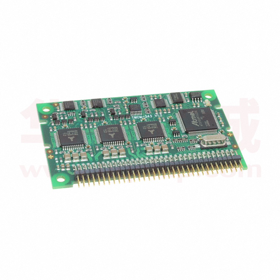


 工商网监
湘ICP备2023018690号
工商网监
湘ICP备2023018690号

