SD603C..C Series
Vishay High Power Products
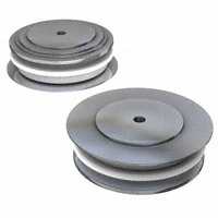
Fast Recovery Diodes (Hockey PUK Version), 600 A
FEATURES
• High power FAST recovery diode series • 1.0 to 2.0 µs recovery time • High voltage ratings up to 2200 V • High current capability
B-43
RoHS
COMPLIANT
• Optimized turn-on and turn-off characteristics • Low forward recovery • Fast and soft reverse recovery • Press PUK encapsulation • Case style conform to JEDEC B-43 • Maximum junction temperature 125 °C • Lead (Pb)-free
PRODUCT SUMMARY
IF(AV) 600 A
• Designed and qualified for industrial level
TYPICAL APPLICATIONS
• Snubber diode for GTO • High voltage freewheeling diode • Fast recovery rectifier applications
MAJOR RATINGS AND CHARACTERISTICS
PARAMETER IF(AV) IF(RMS) TEST CONDITIONS VALUES 600 Ths Ths 50 Hz 60 Hz 50 Hz 60 Hz Range 55 942 25 8320 8715 346 316 400 to 2200 1.0 to 2.0 TJ 25 - 40 to 125 UNITS A °C A °C A
IFSM I2 t VRRM trr TJ
kA2s V µs °C
Document Number: 93178 Revision: 04-Aug-08
For technical questions, contact: ind-modules@vishay.com
www.vishay.com 1
�SD603C..C Series
Vishay High Power Products
ELECTRICAL SPECIFICATIONS VOLTAGE RATINGS
TYPE NUMBER VOLTAGE CODE 04 SD603C..S10C 08 10 12 SD603C..S15C 14 16 SD603C..S20C 20 22 VRRM, MAXIMUM REPETITIVE PEAK AND OFF-STATE VOLTAGE V 400 800 1000 1200 1400 1600 2000 2200 VRSM, MAXIMUM NON-REPETITIVE PEAK VOLTAGE V 500 900 1100 1300 1500 1700 2100 2300 45 IRRM MAXIMUM AT TJ = 125 °C mA
Fast Recovery Diodes (Hockey PUK Version), 600 A
FORWARD CONDUCTION
PARAMETER Maximum average forward current at heatsink temperature Maximum RMS current SYMBOL IF(AV) IF(RMS) TEST CONDITIONS 180° conduction, half sine wave Double side (single side) cooled 25 °C heatsink temperature double side cooled t = 10 ms Maximum peak, one-cycle non-repetitive forward current IFSM t = 8.3 ms t = 10 ms t = 8.3 ms t = 10 ms Maximum I2t for fusing I2t t = 8.3 ms t = 10 ms t = 8.3 ms Maximum I2√t for fusing I 2 √t VF(TO)1 VF(TO)2 rf1 rf2 VFM No voltage reapplied 100 % VRRM reapplied No voltage reapplied 100 % VRRM reapplied VALUES 600 (300) 55 (75) 942 8320 8715 7000 Sinusoidal half wave, initial TJ = TJ maximum 7330 346 316 245 224 3460 1.36 1.81 0.87 0.67 2.97 kA2√s V mΩ V kA2s A UNITS A °C
t = 0.1 to 10 ms, no voltage reapplied (16.7 % x π x IF(AV) < I < π x IF(AV)), TJ = TJ maximum (I > π x IF(AV)), TJ = TJ maximum (16.7 % x π x IF(AV) < I < π x IF(AV)), TJ = TJ maximum (I > π x IF(AV)), TJ = TJ maximum Ipk = 1885 A, TJ = 25 °C; tp = 10 ms sinusoidal wave
Low level value of threshold voltage High level value of threshold voltage Low level of forward slope resistance High level of forward slope resistance Maximum forward voltage drop
RECOVERY CHARACTERISTICS
MAXIMUM VALUE AT TJ = 25 °C CODE trr AT 25 % IRRM (µs) 1.0 1.5 2.0 1000 25 - 30 TEST CONDITIONS Ipk SQUARE PULSE (A) TYPICAL VALUES AT TJ = 125 °C Vr (V) trr AT 25 % IRRM (µs) 2.0 3.2 3.5 Qrr (µC) 45 87 97 Irr (A) 34 51 55
IFM
dI/dt (A/µs)
trr t Qrr IRM(REC)
S10 S15 S20
dir dt
www.vishay.com 2
For technical questions, contact: ind-modules@vishay.com
Document Number: 93178 Revision: 04-Aug-08
�SD603C..C Series
Fast Recovery Diodes Vishay High Power Products (Hockey PUK Version), 600 A
THERMAL AND MECHANICAL SPECIFICATIONS
PARAMETER Maximum operating junction temperature range Maximum storage temperature range Maximum thermal resistance, junction to heatsink Mounting force, ± 10 % Approximate weight Case style See dimensions - link at the end of datasheet SYMBOL TJ TStg DC operation single side cooled RthJ-hs DC operation double side cooled TEST CONDITIONS VALUES - 40 to 125 °C - 40 to 150 0.076 K/W 0.038 9800 (1000) 83 B-43 N (kg) g UNITS
ΔRthJ-hs CONDUCTION
SINUSOIDAL CONDUCTION CONDUCTION ANGLE SINGLE SIDE 180° 120° 90° 60° 30° 0.006 0.008 0.010 0.015 0.026 DOUBLE SIDE 0.007 0.008 0.010 0.015 0.025 SINGLE SIDE 0.005 0.008 0.011 0.016 0.026 DOUBLE SIDE 0.005 0.008 0.011 0.015 0.025 TJ = TJ maximum K/W RECTANGULAR CONDUCTION TEST CONDITIONS UNITS
Note • The table above shows the increment of thermal resistance RthJ-hs when devices operate at different conduction angles than DC
Document Number: 93178 Revision: 04-Aug-08
For technical questions, contact: ind-modules@vishay.com
www.vishay.com 3
�SD603C..C Series
Vishay High Power Products
Fast Recovery Diodes (Hockey PUK Version), 600 A
Maximum Allowable Heatsink T emperature (°C) 130 120 110 100 90 80 70 60 50 DC 40 0 200 400 600 800 1000 Average Forward Current (A) 30° 60° 90° 120° 180°
Conduction Period
Maximum Allowable Heatsink T emperat ure (°C)
130 120 110 100 90 80
S D603C..C S eries (S ingle S ide Cooled) RthJ-hs (DC) = 0.076 K/ W
S D603C..C S eries (Double S Cooled) ide RthJ-hs (DC) = 0.038 K/ W
Conduction Angle
30° 70 0 50 100 150
60°
90° 120° 250
180°
200
300
350
Average Forward Current (A)
Fig. 1 - Current Ratings Characteristics
Fig. 4 - Current Ratings Characteristics
Maximum Allowable Heatsink T emperature (°C)
Maximum Average F orward Power Loss (W)
130 120 110 100 90 80 70 60 0 100 200 300 30° 60° 90° 120° 180° DC 400 500 S D603C..C S eries (S ingle S ide Cooled) RthJ-hs (DC) = 0.076 K/ W
1800 1600 1400 1200 1000 800 600 400 200 0 0 100 200 300 400 500 600 Average Forward Current (A)
Conduction Angle
180° 120° 90° 60° 30° RMS Limit
Conduction Period
S D603C..C S eries T = 125°C J
Average Forward Current (A)
Fig. 2 - Current Ratings Characteristics
Fig. 5 - Forward Power Loss Characteristics
Maximum Allowable Heatsink T emperature (°C)
130 120 110 100
Maximum Average Forward Power Loss (W)
2500 DC 180° 120° 90° 60° 30°
S D603C..C S eries (Double S Cooled) ide R thJ-hs(DC) = 0.038 K/ W
2000
1500
Conduction Angle
90 80 70 60 50 0 100 200 300 400 500 600 700 Average Forward Current (A) 30° 60° 90°
1000
RMS Limit
Conduc tion Period
500
120°
180°
S D603C..C S eries T = 125°C J
0 0 200 400 600 800 1000 Average Forward Current (A)
Fig. 3 - Current Ratings Characteristics
Fig. 6 - Forward Power Loss Characteristics
www.vishay.com 4
For technical questions, contact: ind-modules@vishay.com
Document Number: 93178 Revision: 04-Aug-08
�SD603C..C Series
Fast Recovery Diodes Vishay High Power Products (Hockey PUK Version), 600 A
Peak Half S Wave F ine orward Current (A) 8000 7500
10000 Instantaneous Forward Current (A)
At Any Rated Load Condition and With R ated VRRM Applied Following S urge. Initial T = 125°C J 7000 @60 Hz 0.0083 s 6500 @50 Hz 0.0100 s 6000 5500 5000 4500 4000 3500 3000 2500 1 10 100
Number of Equa l Amplitude Ha lf Cyc le Current Pulses (N)
1000
T = 25 °C J 100 T = 125 °C J
S D603C..C S eries
S D603C..C S eries
10 .5 1.5 2.5 3.5 4.5 5.5 6.5 7.5 8.5 Instantaneous Forward Voltage (V)
Fig. 7 - Maximum Non-Repetitive Surge Current Single and Double Side Cooled
Fig. 9 - Forward Voltage Drop Characteristics
8000 7000 6000 5000 4000 3000
Maximum Non R epetitive S urge Current Versus Pulse T rain Duration. Initial T = 125 °C J No Voltage Reapplied R ated VRRMReapplied
T ransient T hermal Impedance Z thJ-hs (K/ W)
Peak Half S Wave F ine orward Current (A)
9000
0.1 S D603C..C S eries
0.01 S tead y S tate Va lue : RthJ-hs= 0.076 K/ W (S ingle S Cooled) ide RthJ-hs= 0.038 K/ W (Double S Cooled) ide (DC Operation) 0.001 0.001 0.01 0.1 1 10 100
S D603C..C S eries
2000 0.01
0.1 Pulse T rain Duration (s)
1
S quare Wave Pulse Duration (s)
Fig. 8 - Maximum Non-Repetitive Surge Current Single and Double Side Cooled
Fig. 10 - Thermal Impedance ZthJ-hs Characteristics
100
V
FP
80 F orward R overy (V) ec
I
TJ = 125°C
60
40
TJ = 25°C
20 S D603C..S 20C S eries 0 0 200 400 600 800 1000 1200 1400 1600 1800 2000 R ate Off R Of F ise orward Current di/ d t (A/ usec)
Fig. 11 - Typical Forward Recovery Characteristics
Document Number: 93178 Revision: 04-Aug-08
For technical questions, contact: ind-modules@vishay.com
www.vishay.com 5
�SD603C..C Series
Vishay High Power Products
Fast Recovery Diodes (Hockey PUK Version), 600 A
Maximum R everse R ecovery Time - T (µs) rr 4 S D603C..S 15C S eries T = 125 °C; V r = 30V J 3.5
I FM = 1000 A S quare Pulse
Maximum Revers Recovery T e ime - Trr (µs)
2.2 2.1 2 1.9 1.8 1.7 1.6 10
S D603C..S 10C S eries T = 125 °C; V r = 30V J
I FM = 1000 A S quare Pulse
500 A
3
500 A
2.5
250 A
250 A
100
2 10
100
Rate Of Fall Of Forward Current - di/ dt (A/ µs)
Rate Of Fall Of Forward Current - di/d t (A/ µs)
Fig. 12 - Recovery Time Characteristics
Fig. 15 - Recovery Time Characteristics
Maximum Reverse Recovery Charge - Qrr (µC)
Maximum Reverse Rec overy Charge - Qrr (µC)
130 120 110 100 90 80 70 60 50 40 30 S D603C..S 10C S eries T = 125 °C; V r = 30V J
250 A 500 A I FM = 1000 A S quare Pulse
200 180 160 140
500 A I FM = 1000 A S quare Pulse
120 100 80 60 S D603C..S 15C S eries T = 125 °C; V r = 30V J
250 A
20 10 20 30 40 50 60 70 80 90 100
40 10 20 30 40 50 60 70 80 90 100
Rate Of Fall Of Forward Current - di/ dt (A/ µs)
Rate Of Fall Of Forward Current - di/ dt (A/ µs)
Fig. 13 - Recovery Charge Characteristics
Fig. 16 - Recovery Charge Characteristics
Maximum R everse R overy Current - Irr (A) ec
Maximum Reverse Recovery Current - Irr (A)
120 110 100 90 80 70 60 50 40 30 20 S D603C..S 10C S eries T = 125 °C; V r = 30V J
I FM = 1000 A S quare Pulse 500 A 250 A
140 130 120 110 100 90 80 70 60 50 40 30 S D603C..S 15C S eries T = 125 °C; V r = 30V J
250 A 500 A I FM = 1000 A Square Pulse
10 10 20 30 40 50 60 70 80 90 100
20 10 20 30 40 50 60 70 80 90 100
Rate Of Fall Of Forward Current - di/ dt (A/ µs)
Rate Of Fall Of Forward Current - di/ dt (A/µs)
Fig. 14 - Recovery Current Characteristics
Fig. 17 - Recovery Current Characteristics
www.vishay.com 6
For technical questions, contact: ind-modules@vishay.com
Document Number: 93178 Revision: 04-Aug-08
�SD603C..C Series
Fast Recovery Diodes Vishay High Power Products (Hockey PUK Version), 600 A
Maximum R everse Rec overy T ime - T (µs) rr 4.5 S D603C..S 20C S eries TJ= 125 °C; V r = 30V 4
Maximum Reverse Recovery Charge - Qrr (µC) 200 180 160 140 120 100
250 A 500 A I FM = 1000 A S uare Pulse q
3.5
I FM = 1000 A S uare Pulse q
3
500 A
80 60 S D603C..S 20C S eries T = 125 °C; V r = 30V J
2.5
250 A
2 10
100
40 10 20 30 40 50 60 70 80 90 100
Rate Of Fa ll Of Forward Current - di/ dt (A/ µs)
Rate Of Fall Of Forward Current - di/dt (A/ µs)
Fig. 18 - Recovery Time Characteristics
Fig. 19 - Recovery Charge Characteristics
Maximum R everse Recovery Current - Irr (A)
150 140 130 120 110 100 90 80 70 60 50 40 30 S D603C..S 20C S eries T = 125 °C; V r = 30V J
250 A 500 A IFM = 1000 A S quare Pulse
20 10 20 30 40 50 60 70 80 90 100
Rate Of Fall Of Forward Current - di/ dt (A/ µs)
Fig. 20 - Recovery Current Characteristics
1E4
10 4 20 joules per pulse
10 4 2 1 0.4 0.2 0.1 20 joules per pulse
Peak Forward Current (A)
1
2
1E3
0.1 0.04 0.02 0.01
0.4 0.2
1E2
tp
S D603C..S 10C S eries S inusoidal Pulse T = 125°C, VRRM = 1120V J d v/ dt = 1000V/ µs
tp
S D603C..S 10C S eries T rapezoidal Pulse TJ = 125°C, VRRM = 1120V d v/ dt = 1000V/ µs; di/ dt=50A/ µs
1E1 11 E
1E2
1E3
1E 4
11 E
1E2
1E3
1E 4
Pulse Basewidth (µs)
Pulse Basewidth (µs)
Fig. 21 - Maximum Total Energy Loss Per Pulse Characteristics
Document Number: 93178 Revision: 04-Aug-08
For technical questions, contact: ind-modules@vishay.com
www.vishay.com 7
�SD603C..C Series
Vishay High Power Products
Fast Recovery Diodes (Hockey PUK Version), 600 A
1E 4
20 joules p er p ulse 10
20 joules per pulse 10 4 2 1 0.4 0.2
Peak F orward Current (A)
4 2 1
1E 3
0.1 0.04
0.4 0.2
1E 2
0.02
S D603C..S 15C S eries S inusoid al Pulse TJ= 125°C, VRRM = 1760V d v/ dt = 1000V/ µs
tp
tp
S D603C..S 15C S eries T rapezoidal Pulse TJ = 125°C, VRRM = 1760V d v/ dt = 1000V/ µs; di/ dt=50A/ µs
1E 1 11 E
1E2
1E3
1E 4
1E1
1E2
1E 3
1E 4
Pulse Basewidth (µs)
Pulse Basewid th (µs)
Fig. 22 - Maximum Total Energy Loss Per Pulse Characteristics
1E4
20 joules per pulse 10
10 4 2 1 0.4 20 joules per pulse
Peak Forward Current (A)
4
1E3
2 1 0.4 0.2
1E2
0.1 0.04
S D603C..S 20C S eries S inusoidal Pulse T = 125°C, VRRM = 1760V J d v/ dt = 1000V/ µs
S D603C..S 20C S eries T rapezoidal Pulse T = 125°C, VRRM = 1760V J d v/ dt = 1000V/ µs; di/ d t=50A/ µs
tp
tp
1E1 1E1
1E2
1E3
1E4
1E 1
1E2
1E3
1E4
Puls Basewidth (µs) e
Pulse Basewidth (µs)
Fig. 23 - Maximum Total Energy Loss Per Pulse Characteristics
www.vishay.com 8
For technical questions, contact: ind-modules@vishay.com
Document Number: 93178 Revision: 04-Aug-08
�SD603C..C Series
Fast Recovery Diodes Vishay High Power Products (Hockey PUK Version), 600 A
ORDERING INFORMATION TABLE
Device code
SD
1
1 2 3 4 5 6 7
60
2 Diode
3
3
C
4
22
5
S20
6
C
7
Essential part number 3 = Fast recovery C = Ceramic PUK Voltage code x 100 = VRRM (see Voltage Ratings table) trr code (see Recovery Characteristics table) C = PUK case B-43
LINKS TO RELATED DOCUMENTS Dimensions http://www.vishay.com/doc?95249
Document Number: 93178 Revision: 04-Aug-08
For technical questions, contact: ind-modules@vishay.com
www.vishay.com 9
�Legal Disclaimer Notice
Vishay
Disclaimer
All product specifications and data are subject to change without notice. Vishay Intertechnology, Inc., its affiliates, agents, and employees, and all persons acting on its or their behalf (collectively, “Vishay”), disclaim any and all liability for any errors, inaccuracies or incompleteness contained herein or in any other disclosure relating to any product. Vishay disclaims any and all liability arising out of the use or application of any product described herein or of any information provided herein to the maximum extent permitted by law. The product specifications do not expand or otherwise modify Vishay’s terms and conditions of purchase, including but not limited to the warranty expressed therein, which apply to these products. No license, express or implied, by estoppel or otherwise, to any intellectual property rights is granted by this document or by any conduct of Vishay. The products shown herein are not designed for use in medical, life-saving, or life-sustaining applications unless otherwise expressly indicated. Customers using or selling Vishay products not expressly indicated for use in such applications do so entirely at their own risk and agree to fully indemnify Vishay for any damages arising or resulting from such use or sale. Please contact authorized Vishay personnel to obtain written terms and conditions regarding products designed for such applications. Product names and markings noted herein may be trademarks of their respective owners.
Document Number: 91000 Revision: 18-Jul-08
www.vishay.com 1
�


 工商网监
湘ICP备2023018690号
工商网监
湘ICP备2023018690号
