DSA240 Series
AC-DC Power Supplies
240 Watts
xxx Series
• Ultra Slim Design
• 150% Peak Load for 3 seconds
• Ambient Operation from -25 °C to +70 °C
• High Efficiency – Up to 92%
• Selectable Overload Characteristic
• Selectable Remote Inhibit or Enable
• 3 Year Warranty
Dimensions:
DSA240:
4.64 x 4.93 x 2.59” (117.8 x 125.2 x 65.8 mm)
Models & Ratings
Output Voltage
24 V
48 V
Output Power
240 W
240 W
Output Voltage Trim(3)
23.52-25.92 V
47.04-51.84 V
Output Current
10 A
5A
Peak Load(2)
15.0 A
7.5 A
Typical Efficiency(1)
91%
92%
Model Number
DSA240PS24
DSA240PS48
Notes
1. Typical efficiency at 230 VAC and full load.
2. Peak load is for a maximum of 3 s, see Application Notes. Average power is not to exceed nominal output power.
3. Output current should be limited so that nominal output power is not exceeded.
Mechanical Details
4.636
(117.75)
117.7
1
6
Pin Connector
DC O/P
+V
-V +RC -RC
DC
OK
ON
1
2
OCP Mode
RC Mode
DSA240
www.xppower.com
L
4.929 (125.2)
VOUT ADJ.
N
AC I/P
2.591
(65.8)
65.80
1
www.xppower.com
Conn Pin
1
AC
2
I/P
3
1
2
3
DC
O/P
4
5
6
Designation
Ground
L
N
+Vout
-Vout
+RC
-RC
DC OK
DC OK
�DSA240 Series
AC-DC Power Supplies
Input
Characteristic
Minimum
Input Voltage - Operating
90
Input Frequency
47
Power Factor
Typical
50/60
Units
264
VAC
63
Hz
Notes & Conditions
0.95
Input Current - Full Load
At 230 VAC. Conforms to EN61000-3-2 Class A
2.5/1.3
Inrush Current
Earth Leakage Current
Input Protection
Maximum
A
115/230 VAC
33/65
A
At 115/230 VAC
1.0
mA
Maximum
Units
Notes & Conditions
48
VDC
See Models and Ratings table
±1
%
-2/+8
%
See Models and Ratings table
A
No minimum load required
At 264 VAC, 60 Hz
T5.0 A / 250 V internal in-line fuse
Output
Characteristic
Output Voltage - V1
Minimum
Typical
24
Initial Set Accuracy
Output Voltage Adjustment
Minimum Load
0
Start Up Delay
1.0
s
Start Up Rise Time
50
ms
Hold Up Time
20
ms
Line Regulation
±0.5
%
Load Regulation
±1
%
Transient Response - V1
4
%
Ripple & Noise
1
% pk-pk
Overvoltage Protection
At 100% load
At full load and 115 VAC
Recovery within 1% in less than 2 ms
for a 50% step load change at 0.2 A/µs
Measured at 20 MHz bandwidth with 0.1 µF ceramic
capacitor and 47 µF electrolytic
28
33
V
24 V model
56
65
V
48 V model
Overload Protection
%
See Application Notes
Trip & restart (hiccup mode) for 5 cycles then latch.
Recycle AC to reset.
Short Circuit Protection
Thermal Protection
Temperature Coefficient
Remote On/Off
95 (±5)
°C
0.03
%/˚C
Measured on internal heatsink auto recovery
Selectable as Enable or Inhibit using front panel switch
General
Characteristic
Efficiency
Isolation: Input to Output
Input to Ground
Output to Ground
Switching Frequency
Minimum
Typical
91
Maximum
Units
92
%
3000
Notes & Conditions
See Models & Ratings table
VAC
1500
VAC
500
VAC
100
kHz
PFC & Main converter
DC OK Signal
Volt free contacts rated at 60 VDC/0.3 A, 30 VDC/1.0 A or 30 VAC/0.5 A (resistive load)
Output LED
Green LED to indicate output on.
Mean Time Between Failure
Weight
>150
kHrs
1.9 (860)
lb (g)
www.xppower.com
MIL-HDBK-217F, +25 °C GB
2
�DSA240 Series
AC-DC Power Supplies
Environmental
Characteristic
Maximum
Units
Operating Temperature
Minimum
-25
Typical
+70
°C
Storage Temperature
-40
+85
°C
20
95
%RH
3000
m
Natural convection
Cooling
Operating Humidity
Notes & Conditions
See derating curve in Application Notes
Operating Altitude
Non-condensing
Shock
IEC68-2-27, 4 g, 22 ms half sine, 3 times in each of
6 axes
Vibration
IEC68-2-6, 10-500 Hz, 2 g 10 mins/sweep. 60 mins
for each of 3 axes
EMC: Emissions
Phenomenon
Standard
Test Level
Conducted
EN55022
Class B
EN55022
Class B
Harmonic Current
EN61000-3-2
Class A
Voltage Fluctuations
EN61000-3-3
Radiated
Criteria
Notes & Conditions
Criteria
Contact
EMC: Immunity
Phenomenon
Standard
ESD Immunity
EN61000-4-2
Radiated Immunity
EN61000-4-3
Test Level
6 kV
A
8 kV
10 V/m
A
EFT/Burst
EN61000-4-4
3
A
Surges
EN61000-4-5
Installation class 3
A
Conducted
EN61000-4-6
10 V
A
Magnetic Fields
EN61000-4-8
4
Dips and Interruptions
EN55024
Notes & Conditions
Air Discharge
A
Dip: 30%, 10 ms
A
Dip: 60%, 100 ms
A/B
High Line/Low Line
B
Dip: 100%, 5000 ms
Safety Approvals
3
Safety Agency
Safety Standard
Notes & Conditions
UL
UL508
Industrial Control Equipment
TUV
EN60950-1 A12:2011
Information Technology
CB
IEC60950-1 +A1:2009
Information Technology
www.xppower.com
�DSA240 Series
AC-DC Power Supplies
Mechanical Details
4.636
(117.75)
117.7
1
6
Pin Connector
DC O/P
+V
-V +RC -RC
DC
OK
Conn Pin
1
AC
2
I/P
3
1
2
3
DC
O/P
4
5
6
VOUT ADJ.
4.929 (125.2)
ON
1
2
OCP Mode
RC Mode
DSA240
www.xppower.com
L
N
AC I/P
2.591
(65.8)
65.80
Designation
Ground
L
N
+Vout
-Vout
+RC
-RC
DC OK
DC OK
Notes
1. All dimensions in inches (mm)
2. Weight: 1.916 lbs (860g)
3. Tolerance: ±0.02 in (±0.5 mm)
4. Screw terminal: 10-24 AWG cables size.
5. Connection screw maximum torque: Input: 4.4lbs-in (0.5 Nm), Output: 7.0 lbs-in (0.79 Nm).
Application Notes
Derating Curves
100
150
Load (%)
Load (%)
90
For typ. 3sec
112.5
100
Continuous
50
80
70
60
50
40
-25
40
0
10
20
30
40
50
60
70
(Vertical)
90
Ambient Temperature (°C)
100
110
135
230 264Vac
Input Voltage(V)
DC OK
5
6
DCOK
DCOK
Open = Output fail, if voltage drops below 45% of nominal
Closed = Output good
Contact Rating: 0.3 A at 60 VDC, 1.0 A at 30 VDC, 0.5 A at 30 VAC.
500 VDC isolation to output.
www.xppower.com
4
�DSA240 Series
AC-DC Power Supplies
Application Notes
Peak Loading
The peak loading and overload characteristics can be programmed into one of two modes by
appropriate selection of the OCP mode switch on the front panel.
OCP Mode switch set to position 1
I
A peak load of up-to 150% can be taken for a given duration. This duration depends on the
percentage of peak load taken and can be determined by graph A below.
T-peak
I-peak
If the load is reduced to less than 100% of nominal either before or at the end of the duration,
then there is a period of recovery needed to allow the power supply to cool down before the
peak load can be re-applied. The time required for recovery depends on the amount of reduction
of load and can be determined by graph B below.
I-recovery
T-recovery
0
T
However, if the peak load period exceeds the duration indicated by graph A the output will go
into constant current mode for protection. The constant current value will be 105% of the
nominal rating.
During constant current operation, if the output voltage should fall below 40% of the rated
voltage then the output will turn off and try to restart for five times before turning off
permanently. Once this has happened, the output will need to be reset by turning the AC mains
off and on again.
A peak load of up-to 150% can be taken for a given duration. This duration depends on the
percentage of peak load taken as described by graph A.
OCP Mode switch set to position 2
I
Once the peak load duration is exceeded, the output will turn off for 3-4 seconds before
automatically restarting.
T-peak
I-peak
GRAPH A
0
3 ~ 4 sec
T
Peak
duration
GRAPH B
Recovery duration
(Sec.)
(Sec.)
24
22
20
18
16
14
12
10
8
6
4
2
0
22
20
18
16
14
12
10
8
6
4
2
0
110% 115% 120% 125% 130% 135% 140% 145% 150% I-peak
Load (%)
10% 20% 30% 40% 50% 60% 70% 80% 90% I-normal
Load (%)
Remote Control
The output can be controlled by applying a voltage between
pin 3 of the DC output with respect to pin 4. The effect of the
control is dependant upon the RC switch setting on the front
panel.
If the switch is set to position 1 then the output can be
disabled by applying a suitable voltage.
If the switch is set to position 2 then the output can be
enabled by applying a voltage. In the range of 2.5 V to 9.0 V
limited to 20 mA.
Switch Position
Pin 3 Voltage
with respect to Pin 4
Output
1
2.5 V,
很抱歉,暂时无法提供与“DSA240PS48”相匹配的价格&库存,您可以联系我们找货
免费人工找货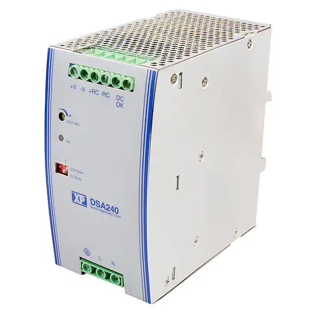


 工商网监
湘ICP备2023018690号
工商网监
湘ICP备2023018690号
