ZMOTION® 20-Pin Detection
and Control Development Kit
Quick Start Guide
QS008502-0813
Introduction
This Quick Start Guide acquaints users with Zilog’s ZMOTION 20-Pin Detection and
Control Development Kit Revision B or later, and provides instructions for setting up and
using the kit to demonstrate its basic operation1. The following topics are covered:
• Getting Started: the quickest way to get the board up and running; see page 2
• Lens Mounting Options – see page 4
• Attaching the Circuit Board Lens – see page 4
Kit Contents
•
•
•
•
•
•
•
•
•
ZMOTION 20-Pin Detection and Control Development Board
USB SmartCable Debugger
0.9" focal flat lens holder
0.77" focal circular lens holder
Selection of lenses (see Table 1 on page 4)
Selection of pyroelectric sensors (RE200B-P is preinstalled on the Board)
Mini-USB serial cable
Wall-mount power supply
Various mounting hardware
1
For a more in-depth approach to assembling and configuring your ZMOTION 20-Pin Detection and
Control Development Kit, Zilog recommends the ZMOTION 20-Pin Detection and Control Development Kit User Manual (UM0239).
Copyright ©2013 Zilog®, Inc. All rights reserved.
www.zilog.com
�ZMOTION® Detection and Control Development Kit
Quick Start Guide
Figure 1 shows the components of the kit, plus the sensors and lenses it contains.
Wall-Mount Power Supply
ZMOTION 20-Pin Detection and Control Development Board
2 additional pyroelectric sensors
Mini-USB Serial Cable
USB Smart Cable Debugger
Lens Holders
Lenses
Figure 1. ZMOTION 20-Pin Detection and Control Development Kit Components
Getting Started
The kit contains a number of lens options. To provide a quick method of getting the kit up
and running, the ZMOTION MCU is initially programmed with a
ZMOTION_Serial_Config project using the CWM 0.5 GI V1 lens. By installing the lens
and then applying power, the basic operation of the kit can be observed.
To get started with the kit, observe the following brief procedure.
1. Install the CWM 0.5 GI V1 lens, as described on page 4.
2. Ensure that jumper J5 is in the WALL position (i.e., positions 2–3 are closed) and that
the Power Switch (SW1) is in the OFF position.
QS008502-0813
Page 2 of 7
�ZMOTION® Detection and Control Development Kit
Quick Start Guide
3. Install the AC plug adapter appropriate for your region into the wall-mount USB power supply.
4. Plug the wall-mount power supply into a suitable AC outlet.
5. Insert the power supply output connector into Mini-USB Plug P1 on the ZMOTION
20-Pin Detection and Control Development Board.
6. Apply power to the Board by sliding Power Switch SW1 to the PWR ON position.
7. The blue 3.3 V power LED (LED1) will illuminate and the red motion LED (LED3)
will initially illuminate and remain on until the pyroelectric sensor stabilizes – a period
of approximately 5 to 30 seconds.
8. After the PIR sensor has stabilized, the red motion LED turns OFF and will turn ON
only when motion is detected.
9. Wave your hand over the lens and observe the red motion LED turning ON for approximately 0.5 seconds.
10. For more information about ZMOTION lens configurations, downloading the ZDS II
application code and additional details, please refer to the ZMOTION 20-Pin Detection
and Control Development Kit User Manual (UM0239).
11. ZMOTION software and documentation are available as a downloadable file from the
Zilog Store. Observe the following steps to install this software.
a. In a web browser, visit zilog.com/store. At the top left, under Categories, click
Downloadable Software to present a list of the available software in the Zilog
Store. In this list, click ZMOTIONL200ZCOG Software and Documentation; the
Product ID for this software is SD00026. On the Product Details page, click the
Add to Cart button and complete the Checkout process to download the
ZMOTION Software and Documentation files to your hard drive. (If you are a
first-time visitor to the Zilog Store, you will be required to register before
downloading this software).
b. When the download is complete, unzip the file to your hard drive, double-click to
launch the ZMOTIONL200ZCOG_.exe installation file, and follow the
on-screen instructions.
c. When the installation is complete, the user manual can be viewed in the following
path:
C:\Program Files\Zilog\ZMOTIONL200ZCOG_\ZMOTION
Lighting Documentation
QS008502-0813
Page 3 of 7
�ZMOTION® Detection and Control Development Kit
Quick Start Guide
Lens Mounting Options
The ZMOTION 20-Pin Detection and Control Development Board supports four lens
mounting options, as indicated in Table 1. For detailed drawings and information about the
lenses, please refer to the ZMOTION Lens and Pyroelectric Sensor Product Specification
(PS0286).
Table 1. Lens Mounting Options
Lens Mounting
PIR Sensor Clip On
Circuit Board Clip In
Circular Lens Holder 0.77 Focal
Flat Lens Holder 0.9 Focal
Lens Supported
NCL-9(26)
NCL-3B
NCL3R
NCL-10S
NCL-10IL
CWM 0.5 GI V1
CM 0.77 GI V3
CM 0.77 GI V5
AA 0.9 GI T1
Note: When mounting the ZMOTION 20-Pin Detection and Control Development
Board vertically or from the ceiling, special consideration should be taken
regarding the height and levelness of the board. Be sure to follow the lens
manufacturer’s recommended height requirements to ensure optimal performance.
Attaching the Circuit Board Lens
This clip-in lens style clips directly into the circuit board over the top of the PIR sensor.
There are 4 mounting clips on the lens that are aligned with the slots in the circuit board.
Note the locating tab on the side of the lens is to be aligned with the silkscreened tab, as
indicated in Figure 2.
QS008502-0813
Page 4 of 7
�ZMOTION® Detection and Control Development Kit
Quick Start Guide
Figure 2. Assembled Clip-In Lens Installed on the ZMOTION 20Pin Detection and Control Development Board
QS008502-0813
Page 5 of 7
�ZMOTION® Detection and Control Development Kit
Quick Start Guide
References
Refer to the documentation in Table 2 for additional information about Zilog’s ZMOTION
products.
Table 2. ZMOTION Documentation
Document
Number
Description
ZMOTION 20-Pin Detection and Control Documentation
PB0225
ZMOTION Detection and Control Product Brief
PS0285
ZMOTION Detection and Control Product Specification
QS0085
This ZMOTION 20-Pin Detection and Control Development Kit Quick Start
Guide
UM0239
ZMOTION 20-Pin Detection and Control Development Kit User Manual
Additional ZMOTION Documentation
PS0286
ZMOTION Lens and Pyroelectric Sensor Product Specification
PB0223
ZMOTION Detection Module Product Brief
PS0284
ZMOTION Detection Module Product Specification
PB0230
ZMOTION Intrusion Detection Product Brief
PS0288
ZMOTION Intrusion Detection Product Specification
RD0001
ZMOTION Intrusion Detection Reference Design
RD0001-SC01
Source code for the ZMOTION Intrusion Detection Reference Design
WP0017
ZMOTION: A New PIR Motion Detection Architecture White Paper
QS0076
ZMOTION Detection and Control Development Kit Quick Start Guide
UM0230
ZMOTION Detection and Control Development Kit User Manual
WP0018
ZMOTION Detection Lens and Pyro Sensor Configuration Guide
AN0301
Power Management and Customer Sensing with Zilog’s ZMOTION
Detection Module
AN0307
ZMOTION Detection Module Application Walkthrough
AN0319
Controlling Power with the ZMOTION Detection Module and Clare
Solid State Relays
QS008502-0813
Page 6 of 7
�ZMOTION® Detection and Control Development Kit
Quick Start Guide
Customer Support
To share comments, get your technical questions answered, or report issues you may be
experiencing with our products, please visit Zilog’s Technical Support page at
http://support.zilog.com.
To learn more about this product, find additional documentation, or to discover other facets about Zilog product offerings, please visit the Zilog Knowledge Base at http://
zilog.com/kb or consider participating in the Zilog Forum at http://zilog.com/forum.
This publication is subject to replacement by a later edition. To determine whether a later
edition exists, please visit the Zilog website at http://www.zilog.com.
Warning: DO NOT USE THIS PRODUCT IN LIFE SUPPORT SYSTEMS.
LIFE SUPPORT POLICY
ZILOG’S PRODUCTS ARE NOT AUTHORIZED FOR USE AS CRITICAL COMPONENTS IN LIFE
SUPPORT DEVICES OR SYSTEMS WITHOUT THE EXPRESS PRIOR WRITTEN APPROVAL OF THE
PRESIDENT AND GENERAL COUNSEL OF ZILOG CORPORATION.
As used herein
Life support devices or systems are devices which (a) are intended for surgical implant into the body, or (b)
support or sustain life and whose failure to perform when properly used in accordance with instructions for use
provided in the labeling can be reasonably expected to result in a significant injury to the user. A critical
component is any component in a life support device or system whose failure to perform can be reasonably
expected to cause the failure of the life support device or system or to affect its safety or effectiveness.
Document Disclaimer
©2013 Zilog, Inc. All rights reserved. Information in this publication concerning the devices, applications, or
technology described is intended to suggest possible uses and may be superseded. ZILOG, INC. DOES NOT
ASSUME LIABILITY FOR OR PROVIDE A REPRESENTATION OF ACCURACY OF THE
INFORMATION, DEVICES, OR TECHNOLOGY DESCRIBED IN THIS DOCUMENT. ZILOG ALSO
DOES NOT ASSUME LIABILITY FOR INTELLECTUAL PROPERTY INFRINGEMENT RELATED IN
ANY MANNER TO USE OF INFORMATION, DEVICES, OR TECHNOLOGY DESCRIBED HEREIN OR
OTHERWISE. The information contained within this document has been verified according to the general
principles of electrical and mechanical engineering.
ZMOTION is a trademark or registered trademark of Zilog, Inc. All other product or service names are the
property of their respective owners.
QS008502-0813
Page 7 of 7
�
很抱歉,暂时无法提供与“ZMOTIONL200ZCOG”相匹配的价格&库存,您可以联系我们找货
免费人工找货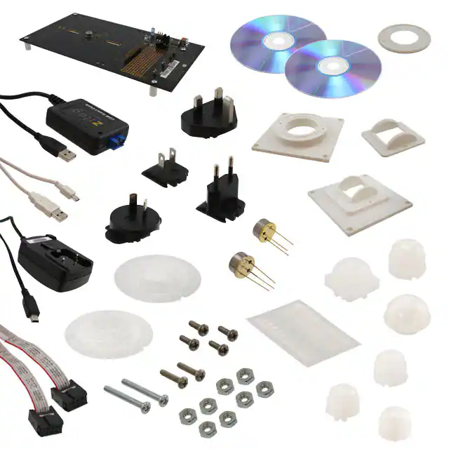


 工商网监
湘ICP备2023018690号
工商网监
湘ICP备2023018690号
