GaAs-IR-Lumineszenzdiode in SMT-Gehäuse GaAs Infrared Emitter in SMT Package SFH 420 SFH 425
SFH 420
SFH 425
Wesentliche Merkmale • GaAs-LED mit sehr hohem Wirkungsgrad • Gute Linearität (Ie = f [IF]) bei hohen Strömen • Gleichstrom- (mit Modulation) oder Impulsbetrieb möglich • Hohe Zuverlässigkeit • Hohe Impulsbelastbarkeit • Oberflächenmontage geeignet • Gegurtet lieferbar • SFH 420 Gehäusegleich mit SFH 320 SFH 425 Gehäusegleich mit SFH 325 • SFH 425: Nur für IR-Reflow-Lötung geeignet. Anwendungen • Miniaturlichtschranken für Gleich- und Wechsellichtbetrieb, Lochstreifenleser • Industrieelektronik • „Messen/Steuern/Regeln“ • Automobiltechnik • Sensorik • Alarm- und Sicherungssysteme • IR-Freiraumübertragung Typ Type Bestellnummer Ordering Code
Features • Very highly efficient GaAs-LED • Good Linearity (Ie = f [IF]) at high currents • DC (with modulation) or pulsed operations are possible • High reliability • High pulse handling capability • Suitable for surface mounting (SMT) • Available on tape and reel • SFH 420 same package as SFH 320 SFH 425 same package as SFH 325 • SFH 425: Suitable only for IR-reflow soldering. Applications • • • • • • • Miniature photointerrupters Industrial electronics For drive and control circuits Automotive technology Sensor technology Alarm and safety equipment IR free air transmission
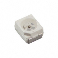
Gehäuse Package Kathodenkennzeichnung: abgesetzte Ecke cathode marking: bevelled edge TOPLED® SIDELED
SFH 420 SFH 425
Q62702-P1690 Q62702-P0330
2001-02-22
1
�SFH 420, SFH 425
Grenzwerte (TA = 25 °C) Maximum Ratings Bezeichnung Parameter Betriebs- und Lagertemperatur Operating and storage temperature range Sperrspannung Reverse voltage Durchlaßstrom Forward current Stoßstrom, τ = 10 µs, D = 0 Surge current Verlustleistung Power dissipation Symbol Symbol Wert Value – 40 … + 100 5 100 3 160 450 Einheit Unit °C V mA A mW K/W
Top; Tstg VR IF IFSM Ptot
Wärmewiderstand Sperrschicht - Umgebung bei RthJA Montage auf FR4 Platine, Padgröße je 16 mm2 Thermal resistance junction - ambient mounted on PC-board (FR4), padsize 16 mm2 each Wärmewiderstand Sperrschicht - Lötstelle bei RthJS Montage auf Metall-Block Thermal resistance junction - soldering point, mounted on metal block Kennwerte (TA = 25 °C) Characteristics Bezeichnung Parameter Wellenlänge der Strahlung Wavelength at peak emission IF = 100 mA, tp = 20 ms Spektrale Bandbreite bei 50% von Imax Spectral bandwidth at 50% of Imax IF = 100 mA Abstrahlwinkel Half angle Aktive Chipfläche Active chip area Abmessungen der aktiven Chipfläche Dimensions of the active chip area Symbol Symbol λpeak
200
K/W
Wert Value 950
Einheit Unit nm
∆λ
55
nm
ϕ
± 60 0.09 0.3 × 0.3
Grad deg. mm2 mm
A L×B L×W
2001-02-22
2
�SFH 420, SFH 425
Kennwerte (TA = 25 °C) Characteristics (cont’d) Bezeichnung Parameter Schaltzeiten, Ιe von 10% auf 90% und von 90% auf 10%, bei IF = 100 mA, RL = 50 Ω Switching times, Ιe from 10% to 90% and from 90% to 10%, IF = 100 mA, RL = 50 Ω Kapazität, Capacitance VR = 0 V, f = 1 MHz Durchlaßspannung, Forward voltage IF = 100 mA, tp = 20 ms IF = 1 A, tp = 100 µs Sperrstrom, Reverse current VR = 5 V Gesamtstrahlungsfluß, Total radiant flux IF = 100 mA, tp = 20 ms Temperaturkoeffizient von Ie bzw. Φe, Symbol Symbol Wert Value 0.5 Einheit Unit µs
tr, tf
Co
25
pF
VF VF IR
1.3 (≤ 1.5) 1.9 (≤ 2.5) 0.01 (≤ 1)
V V µA
Φe
14
mW
TCI
– 0.55
%/K
IF = 100 mA IF = 100 mA
Temperature coefficient of Ie or Φe,
Temperaturkoeffizient von VF, IF = 100 mA Temperature coefficient of VF, IF = 100 mA Temperaturkoeffizient von λ, IF = 100 mA Temperature coefficient of λ, IF = 100 mA
TCV TCλ
– 1.5 + 0.3
mV/K nm/K
2001-02-22
3
�SFH 420, SFH 425
Strahlstärke Ie in Achsrichtung gemessen bei einem Raumwinkel Ω = 0.01 sr Radiant Intensity Ie in Axial Direction at a solid angle of Ω = 0.01 sr Bezeichnung Parameter Strahlstärke Radiant intensity IF = 100 mA, tp = 20 ms Strahlstärke Radiant intensity IF = 1 A, tp = 100 µs Radiation Characteristics Srel = f (ϕ)
40˚ 30˚ 20˚ 10˚ 0˚
OHL01660
Symbol Ie
Werte Values > 2.5
Einheit Unit mW/sr
Ie typ.
38
mW/sr
ϕ
1.0
50˚
0.8
0.6 60˚ 0.4 70˚ 0.2 80˚ 90˚ 100˚ 1.0 0.8 0.6 0.4 0˚ 20˚ 40˚ 60˚ 80˚ 100˚ 120˚ 0
2001-02-22
4
�SFH 420, SFH 425
Relative Spectral Emission Irel = f (λ)
100 %
OHR01938
Radiant Intensity
Ιe = f (IF ) Ιe 100 mA
OHR00864
Single pulse, tp = 20 µs
Ιe Ι e (100 mA) 10 1
Permissible Pulse Handling Capability IF = f (tp), duty cycle D = parameter, TA = 20 °C
10 4
OHR00865
Ι rel
I F mA
5
τ
80
D= τ T D = 0.005
0.01
IF T
60
0.02 10 3 0.05 0.1 0.2
40
10 0
5
20
0.5 DC 10 2 -5 10 10 -4 10 -3 10 -2 10 -1 10 0 10 1 s 10 2 τ
0 880
920
960
1000
nm λ
1060
10 -1 10 -2
10 -1
10 0
A ΙF
10 1
IF = f (VF), single pulse, tp = 20 µs
10 1
OHR01554
Forward Current
Max. Permissible Forward Current IF = f (TA)
120
OHR00883
ΙF
A
I F mA
100
10 0
80
RthjA = 450 K/W
10
-1
60
40
10
-2
20
10 -3
0
1
2
3
4
5
6
V VF
8
0
0
20
40
60
80
100 ˚C 120
TA
2001-02-22
5
�SFH 420, SFH 425
Maßzeichnung Package Outlines
SFH 420
3.0 (0.118) 2.6 (0.102) 2.3 (0.091) 2.1 (0.083)
2.1 (0.083) 1.7 (0.067) 0.1 (0.004) (typ.) 0.9 (0.035) 0.7 (0.028)
(2.4) (0.095)
1.1 (0.043)
3.7 (0.146) 3.3 (0.130) 4˚±1
0.18 (0.007) 0.12 (0.005)
3.4 (0.134) 3.0 (0.118)
Cathode marking
0.5 (0.020)
0.6 (0.024) 0.4 (0.016)
GPLY6724
SFH 425
(2.4 (0.094))
2.8 (0.110)
2.4 (0.094)
4.2 (0.165) 3.8 (0.150)
0.7 (0.028)
1.1 (0.043) Cathode 2.54 (0.100) spacing (1.4 (0.055)) 0.9 (0.035) Anode
(2.85 (0.112))
Cathode marking
(0.3 (0.012))
(2.9 (0.114))
(R1)
4.2 (0.165) 3.8 (0.150)
3.8 (0.150) 3.4 (0.134)
GPLY6880
Maße werden wie folgt angegeben: mm (inch) / Dimensions are specified as follows: mm (inch). 2001-02-22 6
�SFH 420, SFH 425
Löthinweise Soldering Conditions Bauform Types Tauch-, Schwall- und Schlepplötung Dip, Wave and Drag Soldering Lötbadtemperatur Maximal zulässige Lötzeit Abstand Lötstelle – Gehäuse Reflowlötung Reflow Soldering Lötzonentemperatur Maximale Durchlaufzeit
Temperature Max. Perm. Distance of the Soldering Time between Soldering Bath Solder Joint and Case TOPLED SIDELED 260 °C – 10 s – – –
Temperature of Soldering Zone 245 °C ≥ 225 °C
Max. Transit Time
10 s 10 s
Zusätzliche Informationen über allgemeine Lötbedingungen erhalten Sie auf Anfrage. For additional information on general soldering conditions please contact us.
Published by OSRAM Opto Semiconductors GmbH & Co. OHG Wernerwerkstrasse 2, D-93049 Regensburg © All Rights Reserved. Attention please! The information describes the type of component and shall not be considered as assured characteristics. Terms of delivery and rights to change design reserved. Due to technical requirements components may contain dangerous substances. For information on the types in question please contact our Sales Organization. Packing Please use the recycling operators known to you. We can also help you – get in touch with your nearest sales office. By agreement we will take packing material back, if it is sorted. You must bear the costs of transport. For packing material that is returned to us unsorted or which we are not obliged to accept, we shall have to invoice you for any costs incurred. Components used in life-support devices or systems must be expressly authorized for such purpose! Critical components 1 , may only be used in life-support devices or systems 2 with the express written approval of OSRAM OS. 1 A critical component is a component usedin a life-support device or system whose failure can reasonably be expected to cause the failure of that life-support device or system, or to affect its safety or effectiveness of that device or system. 2 Life support devices or systems are intended (a) to be implanted in the human body, or (b) to support and/or maintain and sustain human life. If they fail, it is reasonable to assume that the health of the user may be endangered. 2001-02-22 7
�


 工商网监
湘ICP备2023018690号
工商网监
湘ICP备2023018690号
