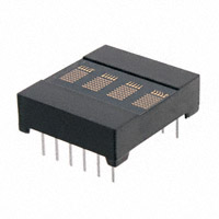
0.145" 4-Character 5 x 7 Dot Matrix
Alphanumeric Intelligent Display® Devices with Memory/Decoder/Driver
Lead (Pb) Free Product - RoHS Compliant
DLR1414, DLO1414, DLG1414
Description
The DLR/DLO/DLG1414 is a four digit 5 x 7 dot matrix display module with a built-in CMOS integrated circuit.
The integrated circuit contains memory, ASCII ROM decoder, multiplex circuitry and drivers. Data entry is asynchronous and random. A display system can be built using any number of DLX1414s since each character in any DLX1414
can be addressed independently and will continue to display the character last stored until replaced by another.
System interconnection is very straightforward. The least significant two address bits (A0, A1) are normally connected
to the like named inputs of all displays in the system. Data lines are connected to all DLX1414s directly and in parallel
as is the write line (WR). The display then will behave as a write only memory.
The DLX1414 has several features superior to competitive devices. The character set consists of 128 special ASCII
characters for English, German, Italian, Swedish, Danish, and Norwegian.
Features
• 0.145" High, Dot Matrix Character
• 128 Special ASCII Characters for English, German,
Italian, Swedish, Danish, and Norwegian
Languages
• Wide Viewing Angle: X Axis ±50°, Y Axis ±75°
• Close Vertical Row Spacing, 0.800" Centers
• Fast Access Time, 110 ns at 25°C
• Compact Size for Hand Held Equipment
• Built-in Memory
• Built-in Character Generator
Built-in Multiplex and LED Drive Circuitry
• Direct Access to Each Digit Independently and Asynchronously
• TTL Compatible, 5.0 Volt Power
• Low Power Consumption, 20 mA per Character Typical
• Intensity Coded for Display Uniformity
• Extended Operating Temperature Range:
–40°C to +85°C
• End Stackable, 4-Character Package
See Appnotes 18, 19, 22, and 23 for additional
information.
Ordering Information
Type
Color of Emission
Ordering Code
DLR1414
red
Q68000A8091
DLO1414
high efficiency red
Q68000A8092
DLG1414
green
Q68000A8093
2006-01-23
1
�DLR1414, DLO1414, DLG1414
EIA
Date Code
0.25 (0.010) 4 pl.
Part
Number
Luminous
Intensity Code
0.46 (0.018) 12 pl.
0.3 (0.012) ±0.05 (0.002) 12 pl.
2.54 (0.100) 10 pl.
At Seating Plane
2.41 (0.095) ref.
15.24 (0.600) ±0.51 (0.020)
17.78 (0.700) max.
4.06 (0.160) ±0.51 (0.020)
DLX1414 Z
OSRAM YYWW V
6.1 (0.240) ref.
1.78 (0.070) ±0.08 (0.003) 4 pl.
5.33 (0.210)
1.27 (0.050) 4 pl.
Pin 1
Indicator
4.45 (0.175)
2.34 (0.092)
3.66 (0.144)
0.56 (0.022)
20.32 (0.800) max.
0.51 (0.020)
Tolerance: ±0.254 (0.010)
IDOD5218
2006-01-23
2
�DLR1414, DLO1414, DLG1414
Maximum Ratings
Parameter
Symbol
Value
Unit
Operating temperature range
Top
– 40 … + 85
°C
Storage temperature range
Tstg
– 40 … + 100
°C
DC supply voltage
– 0.5 … + 7.0
V
Input voltage levels relative to GND (all inputs)
– 0.5 to VCC + 0.5
V
Solder temperature 0.063“ (1.59 mm)
below seating plane, t < 5.0 s
Ts
260
°C
Relative humidity at 85°C
RH
85
%
Characteristics
(TA = 25 °C)
Wavelength at peak emission
IF = 0 mA
Viewing angle (off normal axis)
(typ.)
hor. (typ.)
ver. (typ.)
Character Height
Time averaged luminous intensity1)
(100% brightness, VCC = 5.0 V)
(typ.)
LED to LED intensity matching
(max.)
LED to LED hue matching at VCC = 5.0 V
(max.)
1)
red
high
green
efficiency
red
λpeak
660
630
565
nm
2ϕ
±50
±75
±50
±75
±50
±75
deg
deg.
h
0.145
3.7
0.145
3.7
0.145
3.7
inch
mm
50
60
70
µcd/LED
1.8:1.0
1.8:1.0
1.8:1.0
±2.0
Peak luminous intensity values can be calculated by multiplying these values by 7.
2006-01-23
Unit
DLG1414
Values
DLO1414
Symbol
DLR1414
Parameter
3
nm
�DLR1414, DLO1414, DLG1414
Top View
12
11
10
9
8
7
Digit 3 Digit 2 Digit 1 Digit 0
1
2
3
4
5
6
IDPA5301
DC Characteristics
Parameter
–40°C
+25°C
+85°C
Unit
Condition
Min.
Typ.
Max.
Min.
Typ.
Max.
Min.
Typ.
Max.
ICC 4 Digits
on 20
dots/digit
—
90
120
—
80
105
—
70
95
mA
VCC=5.0 V
ICC Blank
—
2.8
4.0
—
2.3
3.0
—
2.0
2.5
mA
VCC=5.0 V,
WR=5.0 V
VIN=0 V
IIL (all
inputs)
30
60
120
25
50
100
20
40
80
µA
VIN=0.8 V,
VCC=5.0 V
VIH
2.0
—
—
2.0
—
—
2.0
—
—
V
VCC=5.0 V
±0.5 V
VIL
—
—
0.8
—
—
0.8
—
—
0.8
V
VCC=5.0 V
±0.5 V
VCC
4.5
5.0
5.5
4.5
5.0
5.5
4.5
5.0
5.5
V
—
Pins and Functions
Pin
Function
Pin
Function
Pin
Function
1
D5 Data Input
5
A0 Digit Select
9
D1 Data Input
2
D4 Data Input
6
VCC
10
D2 Data Input
3
WR Write
7
GND
11
D3 Data Input
4
A1 Digit Select
8
D0 Data Input (LSB)
12
D6 Data Input (MSB)
2006-01-23
4
�DLR1414, DLO1414, DLG1414
Timing Characteristics (VCC=4.5 V)
2.0 V
0.8 V
A0, A1
TAH
TAS
2.0 V
0.8 V
D0-D6
TDS
TDH
WR
2.0 V
0.8 V
TW
TACC
Note: These waveforms are not edge triggered.
AC Characteristics (guaranteed minimum timing parameters at VCC=5.0 V ±0.5 V)
Parameter
Symbol
–40°C
+25°C
+85°C
Unit
Address Set Up Time
TAS
10
10
10
ns
Address Hold Time
TAH
20
30
40
ns
Write Time
TW
60
70
90
ns
Data Set Up Time
TDS
20
30
50
ns
Data Hold Time
TDH
20
30
40
ns
TACC
90
110
140
ns
Access Time
1)
1)
TACC= Set Up Time + Write Time + Hold Time.
2006-01-23
5
�DLR1414, DLO1414, DLG1414
Loading Data State Table
WR
A1
A0
D6
D5
D4
D3
D2
D1
D0
Display Digit
3
2
1
0
G
R
E
Y
H
previously loaded display
L
L
L
H
L
L
L
H
L
H
G
R
E
E
L
L
H
H
L
H
L
H
L
H
G
R
U
E
L
H
L
H
L
L
H
H
L
L
G
L
U
E
L
H
H
H
L
L
L
L
H
L
B
L
U
E
L
L
H
H
L
L
H
H
L
H
B
L
E
E
L
L
L
H
L
H
L
H
H
H
B
L
E
W
L
X
X
see character code
see character set
X=Don’t care
Typical Interconnection for 32 Characters
+V
GND
D8 D7
D4 D3
D0
D0-D6
A0-A1
WR
D31 D28 D27 D24 D23 D20 D19 D16 D15 D12 D11
D0-D6 7
DATA
A0, A1 2
ADDRESS
ADDRESS
A2
A3
A4
WRITE
7
6
A 5
B 4
C 3
G 2
1
0
IDCD5040
74138
2006-01-23
6
�DLR1414, DLO1414, DLG1414
Block Diagram
Display
Rows 0 to 6
3
2
1
0
Row Control Logic
&
Row Drivers
OSC
128
Counter
Columns 0 to 19
Timing and Control Logic
7
Counter
RAM
Memory
4 x 7 bit
WR
A0
A1
Write
Address
Decoder
7-bit ASCII Code
Latches
D6
D5
D4
D3
D2
D1
D0
Row Decoder
Column Decoder
RAM Read Logic
ROM
128 x 35 bit
ASCII
Character
Decode
4480 bits
Column Data
Column
Enable
Latches and
Column
Drivers
IDBD5072
2006-01-23
7
�DLR1414, DLO1414, DLG1414
Character Set
D0
D1
D2
D3
D6 D5 D4 HEX
ASCII
CODE
0 0 0
0
0 0 1
1
0 1 0
2
0 1 1
3
1 0 0
4
1 0 1
5
1 1 0
6
1 1 1
7
0
0
0
0
0
1
0
0
0
1
0
1
0
0
2
1
1
0
0
3
0
0
1
0
4
1
0
1
0
5
0
1
1
0
6
1
1
1
0
7
0
0
0
1
8
1
0
0
1
9
0
1
0
1
A
1
1
0
1
B
0
0
1
1
C
1
0
1
1
D
0
1
1
1
E
1
1
1
1
F
IDCS5087
Notes:
1. High=1 level
2. Low= 0 level
3. Upon power up, the device will initialize in a random state.
2006-01-23
8
�DLR1414, DLO1414, DLG1414
Revision History: 2006-01-23
Previous Version: 2004-11-04
Page
Subjects (major changes since last revision)
Date of change
all
completely rework
2004-08-31
all
Lead free device
2006-01-23
Attention please!
The information describes the type of component and shall not be considered as assured characteristics.
Terms of delivery and rights to change design reserved. Due to technical requirements components may contain
dangerous substances. For information on the types in question please contact our Sales Organization.
If printed or downloaded, please find the latest version in the Internet.
Packing
Please use the recycling operators known to you. We can also help you – get in touch with your nearest sales office.
By agreement we will take packing material back, if it is sorted. You must bear the costs of transport. For packing
material that is returned to us unsorted or which we are not obliged to accept, we shall have to invoice you for any costs
incurred.
Components used in life-support devices or systems must be expressly authorized for such purpose! Critical
components1) may only be used in life-support devices or systems2) with the express written approval of OSRAM OS.
1)
A critical component is a component used in a life-support device or system whose failure can reasonably be expected to cause the failure
of that life-support device or system, or to affect its safety or the effectiveness of that device or system.
2)
Life support devices or systems are intended (a) to be implanted in the human body, or (b) to support and/or maintain and sustain human
life. If they fail, it is reasonable to assume that the health and the life of the user may be endangered.
2006-01-23
9
�DLR1414, DLO1414, DLG1414
Design Considerations
For details on design and applications of the DLX1414 using
standard bus configurations in multiple display systems, or parallel
I/O devices, such as the 8255 with an 8080 or memory mapped
addressing on processors such as the 8080, Z80, 6502, 8748, or
6800, refer to Appnote 15 at www.osram-os.com.
Electronics, Inc., Frenchtown, NJ; Garry Manufacturing, New Brunswick, NJ; Robinson-Nugent, New Albany, IN; and Samtec Electronic Hardware, New Albany, IN.
For further information refer to Appnote 22 at www.osram-os.com.
Optical Considerations
The .145" high characters of the DLX1414 gives readability up to
eight feet. The user can build a display that enhances readability
over this distance by proper filter selection.
Using filters emphasizes the contrast ratio between a lit LED and
the character background. This will increase the discrimination of
different characters. The only limitation is cost. Remember to take
into consideration the ambient lighting environment for the best
cost/benefit ratio for filters.
Incandescent (with almost no green) or fluorescent (with almost no
red) lights do not have the flat spectral response of sunlight. Plastic band-pass filters are an inexpensive and effective way to
strengthen contrast ratios. The DLR1414 is a standard red display
and should be matched with long wavelength pass filter in the 600
nm to 620 nm range. For displays of multiple colors, neutral density grey filters offer the best compromise.
The DLO1414 is a high efficiency red display and should be
matched with a long wavelength pass filter in the 570 nm to
590 nm range. The DLG1414 should be matched with a yellow-green band-pass filter that peaks at 565 nm. For displays of
multiple colors, neutral density gray filters offer the best compromise.
Additional contrast enhancement can be gained by shading the
displays. Plastic band-pass filters with built-in louvers offer the next
step up in contrast improvement. Plastic filters can be improved
further with anti-reflective coatings to reduce glare. The trade-off is
fuzzy characters. Mounting the filters close to the display reduces
this effect. Take care not to overheat the plastic filter by allowing for
proper air flow.
Optimal filter enhancements are gained by using circular polarized, anti-reflective, band-pass filters. The circular polarizing further enhances contrast by reducing the light that travels through
the filter and reflects back off the display to less than 1%.
Several filter manufacturers supply quality filter materials. Some of
them are: Panelgraphic Corporation, W. Caldwell, NJ; SGL Homalite, Wilmington, DE; 3M Company, Visual Products Division, St.
Paul, MN; Polaroid Corporation, Polarizer Division, Cambridge,
MA; Marks Polarized Corporation, Deer Park, NY, Hoya Optics,
Inc., Fremont, CA.
One last note on mounting filters: recessing displays and bezel
assemblies is an inexpensive way to provide a shading effect in
overhead lighting situations. Several bezel manufacturers are:
R.M.F. Products, Batavia, IL; Nobex Components, Griffith Plastic
Corp., Burlingame, CA; Photo Chemical Products of California,
Santa Monica, CA; I.E.E.-Atlas, Van Nuys, CA.
Refer to Appnote 23 at www.osram-os.com.
Electrical & Mechanical Considerations
Voltage Transient Suppression
We strongly recommend that the same power supply be used for
the display and the components that interface with the display to
avoid logic inputs higher than VCC. Additionally, the LEDs may
cause transients in the power supply line while they change display states. The common practice is to place .01 mF capacitors
close to the displays across VCC and GND, one for each display,
and one 10 mF capacitor for every second display.
ESD Protection
The metal gate CMOS IC of the DLX1414 is extremely immune to
ESD damage. However, users of these devices are encouraged to
take all the standard precautions, normal for CMOS components.
These include properly grounding personnel, tools, tables, and
transport carriers that come in contact with unshielded parts.
Where these conditions are not, or cannot be met, keep the leads
of the device shorted together or the parts in anti-static packaging.
Soldering Considerations
The DLX1414 can be hand soldered with SN63 solder using a
grounded iron set to 260×C.
Wave soldering is also possible following these conditions: Preheat
that does not exceed 93×C on the solder side of the PC board or a
package surface temperature of 85×C. Water soluble organic acid
flux (except carboxylic acid) or rosin-based RMA flux without
alcohol can be used.
Wave temperature of 245×C ±5×C with a dwell between 1.5 sec. to
3.0 sec. Exposure to the wave should not exceed temperatures
above 260×C for five seconds at 0.063" below the seating plane.
The packages should not be immersed in the wave.
Post Solder Cleaning Procedures
The least offensive cleaning solution is hot D.I. water (60 ×C) for
less than 15 minutes. Addition of mild saponifiers is acceptable. Do
not use commercial dishwasher detergents.
For faster cleaning, solvents may be used. Carefully select solvents as some may chemically attack the nylon package. Maximum exposure should not exceed two minutes at elevated
temperatures. Acceptable solvents are TF (trichlorotrifluorethane),
TA, 111 Trichloroethane, and unheated acetone.
Note: Acceptable commercial solvents are: Basic TF, Arklone P,
Genesolve D, Blaco-tron TF, Genesolve DA, and Blaco-tron TA.
Unacceptable solvents contain alcohol, methanol, methylene chloride, ethanol, TP35, TCM, TMC, TMS+, TE, or TES. Since many
commercial mixtures exist, contact a solvent vendor for chemical
composition information. Some major solvent manufacturers are:
Allied Chemical Corporation, Specialty Chemical Division, Morristown, NJ; Baron-Blakeslee, Chicago, IL; Dow Chemical, Midland,
MI; E.I. DuPont de Nemours & Co., Wilmington, DE.
For further information refer to Appnotes 18 and 19 at
www.osram-os.com.
An alternative to soldering and cleaning the display modules is to
use sockets. Eighteen pin DIP sockets .600" wide with .100" centers work well for single displays. Multiple display assemblies are
best handled by longer SIP sockets or DIP sockets when available
for uniform package alignment. Socket manufacturers are Aries
2006-01-23
Published by
OSRAM Opto Semiconductors GmbH
Wernerwerkstrasse 2, D-93049 Regensburg
www.osram-os.com
© All Rights Reserved.
10
�


 工商网监
湘ICP备2023018690号
工商网监
湘ICP备2023018690号
