Reference
Manual
DOC. REV. 4/9/2013
VL-ENCL-5
Development
Enclosure
�WWW.VERSALOGIC.COM
12100 SW Tualatin Road
Tualatin, OR 97062-7341
(503) 747-2261
Fax (971) 224-4708
Contents Copyright ©2013
All Rights Reserved
Notice:
Although every effort has been made to ensure this document is error-free, VersaLogic makes no
representations or warranties with respect to this product and specifically disclaims any implied warranties
of merchantability or fitness for any particular purpose.
VersaLogic reserves the right to revise this product and associated documentation at any time without
obligation to notify anyone of such changes.
PC/104 and the PC/104 logo are trademarks of the PC/104 Consortium.
The SUMIT name and logo are trademarks of the Small Form Factor Special Interest Group.
VL-ENCL-5 Reference Manual
ii
�Table of Contents
Introduction ............................................................................................................................... 1
Description ....................................................................................................................................... 1
Features ............................................................................................................................... 1
Models ................................................................................................................................ 1
Technical Specifications .................................................................................................................. 2
Accessories / Options ...................................................................................................................... 2
Recommended Tools ....................................................................................................................... 2
Parts List .......................................................................................................................................... 3
Metal Parts .......................................................................................................................... 3
Hardware............................................................................................................................. 3
Front and Back Panels ............................................................................................................. 4
VL-ENCL-5A Front Panel ............................................................................................................... 4
VL-ENCL-5B Front Panel ............................................................................................................... 4
VL-ENCL-5C Front Panel ............................................................................................................... 5
VL-ENCL-5D Front Panel ............................................................................................................... 5
Installation ................................................................................................................................. 7
Procedure ......................................................................................................................................... 7
Enclosure Lid .......................................................................................................................... 12
Installation ..................................................................................................................................... 12
VL-ENCL-5 Reference Manual
iii
�Introduction
Description
The VL-ENCL-5 provides easy access, superb protection and portable convenience for products
under development. A single board computer (SBC), EBX, EPIC or PC/104 format, installs on
top of the unit and I/O device cables attach to the front panel for making connections easier.
FEATURES
Low cost enclosure for prototype and
development use
Front connector panel for easy
accessibility
Properly supports SBC for repeated
insertion and removal of PC/104
expansion modules (without excess
board flex)
Lid accommodates up to two PC/104
boards on top of the SBC (or one
expansion board with a dual-board
computer)
Protects system components during
development
Provides system portability during
development
Provides full access to the top of the
SBC
Improves appearance of system for
demonstration purposes
Accommodates:
EBX, EPIC, PC/104, PC/104-Plus, and
SUMIT SBCs
PC/104 expansion boards
ATX style power supply
5.25” CD-ROM drive
2.5” or 3.5” hard drive
MODELS
There are four models of the VL-ENCL-5, which accommodate computers with different
interfaces and breakout boards. See KnowledgeBase article VT1630 - VL-ENCL-5 Models for
VersaLogic SBCs for information on the appropriate VL-ENCL-5 model for your computer.
Model
Front Panel Cutouts
Drive Bays
VL-ENCL5a
COM (4), USB (4), LPT/floppy, PS/2
mouse, PS/2 keyboard, audio in, audio out,
digital I/O, analog I/O, LEDs, reset button
One 3.5”/2.5” internal drive bay, one 5.25”
external access drive bay.
VL-ENCL5b
COM (4), video out, LPT, PS/2 mouse,
PS/2 keyboard, Ethernet (2), LEDs, reset
button, speaker.
One 3.5”/2.5” internal drive bay, one
external access 3.5” floppy drive bay, one
5.25” external access drive bay.
VL-ENCL5c
COM (4), video out, LPT, Ethernet, PS/2
(2) or USB (4), depending on cable used,
LEDs, reset button.
Two 3.5”/2.5” internal drive bays, one 5.25”
external access drive bay.
VL-ENCL5d
COM (2), USB (3), video out, audio in,
audio out, power, LEDs, reset button.
Two 3.5”/2.5” internal drive bays, one 5.25”
external access drive bay.
The back panel of all models includes cutouts for CompactFlash, Ethernet (2), video, USB (2),
audio in, audio out, and mic.
VL-ENCL-5 Reference Manual
1
�Technical Specifications
Size:
13.12” W x 10.2” D x 4.5” H
Connector Panel:
Accommodates (depending on configuration) VGA, PS/2 keyboard and mouse, COM (4), LPT,
RJ45 (Ethernet, 2), USB (4), sound and mic jacks, reset switch, LEDs (2), speaker, 50-pin cable
exit slot, CompactFlash
Expansion Modules:
Accommodates two PC/104 boards on EBX and EPIC form factor SBCs (or one expansion board
with a dual-board computer)
Material:
Light gauge steel
Finish:
Black powder coat
Accessories / Options
The following accessories and options for the VL-ENCL-5 are available from VersaLogic:
VL-CDD-IDE1
CD-RW, DVD-ROM, Internal
VL-ENCL-3HS
Handle set
VL-ENCL5LID
Tilt lid for VL-ENCL-5
VL-FDD-144
3.5” floppy drive, 1.44 MB
VL-HDD-35-xx
3.5” hard drive
VL-HDW-101
Metric standoff package - PC/104
VL-HDW-105
Metric standoff package - SUMIT
VL-HDW-201
PC/104 extractor tool
VL-HDS35-320
320 GB 3.5” SATA hard drive
VL-PS200-ATX
200 watt ATX style power supply
Recommended Tools
ESD protected work area
3/16” and 7/32” hex drivers
Flathead screwdriver
Needle nose pliers
Phillips screwdriver
VL-ENCL-5 Reference Manual
2
�Parts List
The enclosure includes the following hardware:
METAL PARTS
Enclosure base
Enclosure top
Front panel
Drive mounting bracket
HARDWARE
Screws for assembly of metal parts
(15)
(2)
Enclosure mounting feet for stability on the bench top
(4)
Enclosure attachment screw 4-40 x 1/4”
Enclosure attachment screw 6-32 x 3/8”
Rubber feet
Hardware kit HDW-ENCL5 for the installation of circuit board hardware and devices
(7)
D-Sub jack screw sets for attaching connectors to front and rear
panels
(20)
M3 nuts for use with hex standoffs
(12)
Black Phillips pan head screws, 6-32 x 1/4”, for use in securing
drives and devices
(32)
Phillips pan head screws, 3mm x 6mm, for use in securing drives
and standoffs
(4)
5mm x 10mm M3 hex standoff for use in mounting EPIC paddle
board
(12)
5mm x 15.24mm M3 hex standoff (brass with black oxide) for use
in mounting SBC and paddle boards
VL-ENCL-5 Reference Manual
3
�Front and Back Panels
VL-ENCL-5 models have different front panels to accommodate various VersaLogic breakout
board and connector configurations. Each front panel option is shown below.
VL-ENCL-5A Front Panel
Figure 1. VL-ENCL-5A Front Panel
VL-ENCL-5B Front Panel
Figure 2. VL-ENCL-5B Front Panel
VL-ENCL-5 Reference Manual
4
�VL-ENCL-5C Front Panel
Figure 3. VL-ENCL-5C Front Panel
VL-ENCL-5D Front Panel
Figure 4. VL-ENCL-5D Front Panel
VL-ENCL-5 Reference Manual
5
�CBL-4404
COMPACT FLASH
ETHERNET
VIDEO
AUDIO
IN
OUT
MIC
ETHERNET
USB3
USB4
Figure 5. VL-ENCL-5 Back Panel (All Models)
VL-ENCL-5 Reference Manual
6
�Installation
Follow the procedure below to install a VersaLogic computer in the VL-ENCL-5. Skip any steps
that do not apply to your computer or configuration.
The VL-ENCL-5B enclosure is shipped assembled to minimize cosmetic damage to the painted
parts.
Procedure
1.
Remove the enclosure top and front panel.
The top of the enclosure is secured with eight screws. The front panel is secured with three
screws.
2.
Install standoffs to the base of the VL-ENCL-5 to support the breakout board.
Breakout boards are typically secured using four 5mm x 15mm standoffs with four 3mm x
6mm screws.
Note: The CBL/CBR-4004 breakout board can be mounted to the back panel using four
5mm x 10mm standoffs with 3mm x 6mm screws.
3.
4.
Install the drives (HD, CD-ROM, FDD).
Install the CD-ROM drive in bottom bay. Secure it with eight 3mm x 6mm screws.
Install the floppy drive inside the middle bay. The front panel of the floppy drive should
be flush with the front panel of the CD drive. Secure the floppy drive with six 3mm x
6mm screws.
Install the hard drive in the top bay. The drive’s power and data connectors should point
toward the back panel of the enclosure base. Secure 3.5” drives with six 3mm x 6mm
screws from the sides, or a 2.5” drive with four screws from the top. Some drives use 632 x 1/4” screws, which are also supplied in the hardware kit.
Attach the breakout board to the base.
Secure the breakout board to the standoffs installed in step 2 with four M3 nuts.
5.
Reinstall the front panel using the screws removed in step 1.
6.
Secure the breakout board to the front panel.
Use three D-Sub jack screw sets to secure the breakout board to the front panel. If your
application uses an additional breakout board (such as an industrial I/O board), secure it to
the front panel with D-Sub jack screw sets.
7.
Install front and rear panel connectors.
Connectors to install can include VGA video, Ethernet, or others. These either snap into the
appropriate cutouts or are secured with D-Sub jack screw sets.
8.
Install the ATX power supply.
Place the power supply inside the enclosure with the switch and fan positioned against the
back panel of enclosure base. Use four 6-32 x 1/4” screws to secure the power supply to the
back panel.
9.
Install the enclosure handles.
Secure the handles to the sides of the enclosure top with the screws provided.
VL-ENCL-5 Reference Manual
7
�10. Install standoffs to the top to support the computer.
The following figures show where to install standoffs to the top of the VL-ENCL-5 to
support the computer.
Warning!
Be sure to use the correct size standoffs for your computer. SUMIT boards
must use the standoffs and screws available as part number VL-HDW-105.
These standoffs are 15.25 mm (0.60 inch), and must not be mixed with the
15.0 mm standoffs used for non-SUMIT boards. Using the standoffs
available as VL-HDW-101 on SUMIT boards will result in damage to the
board.
Figure 6. Standoff Positions for PC/104 Boards
Figure 7. Standoff Positions for EBX Boards
VL-ENCL-5 Reference Manual
8
�Figure 8. Standoff Positions for EPIC Boards
11. Reinstall the enclosure top.
Thread the breakout board, back panel, power, and drive cables through the holes in the
enclosure top while keeping the vent towards the drive bay. Place the top over the
components and secure it with the screws removed in step 1.
12. Attach the computer to the standoffs.
Place the board on the standoffs and use M3 nuts to secure the board to the enclosure.
Dual-board computers: If your computer is a dual-board set, you must separate the two
boards before securing it to the enclosure. After separating the boards, secure the south
board to the enclosure, and then re-mate the dual-board set, using care not to bend any pins
or misalign the inter-board connectors. Improper alignment could result in damage to the
computer.
13. Connect the cables.
See the reference manual for your computer for proper cable connections. The following
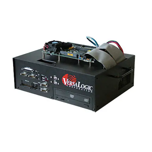
figures show examples of complete installations of PC/104, EBX, and EPIC computers.
VL-ENCL-5 Reference Manual
9
�Figure 9. Example PC/104 Board Installation
Figure 10. Example EBX Board Installation
VL-ENCL-5 Reference Manual
10
�Figure 11. Example EPIC Board Installation
VL-ENCL-5 Reference Manual
11
�Enclosure Lid
The optional enclosure lid includes the following parts.
Metal Parts:
Enclosure lid
Hardware:
(1)
(1)
(2)
3” strip double-sided foam tape 1/2”
36” strip double-sided foam tape 1/2”
Shoulder washers
Installation
The VL-ENCL-5 lid (VL-ENCL5LID) is shipped unassembled with the enclosure lid hardware
kit. Follow the procedure below to install the lid.
1. Remove the two screws from the rear of top enclosure.
These are two 6-32 x 3/8” screws that will be reused to install the lid.
2. Tape the front tabs.
Cut the 3” foam tape in half and place it on the front tabs.
3. Mount the flat pane display.
Cut the 36” foam tape into appropriate size strips and use it to mount the display.
4. Install the shoulder washers.
Install one shoulder washer on each inside lid flange, on both sides of top.
5. Reinstall the lid using the screws removed in step 1.
VL-ENCL-5 Reference Manual
12
�


 工商网监
湘ICP备2023018690号
工商网监
湘ICP备2023018690号
