Web Site: www.parallax.com
Forums: forums.parallax.com
Sales: sales@parallax.com
Technical: support@parallax.com
Office: (916) 624-8333
Fax: (916) 624-8003
Sales: (888) 512-1024
Tech Support: (888) 997-8267
Parallax Standard Servo (#900-00005)
The Parallax Standard Servo provides 180° range of motion and position control to your project. Great
for animatronics and robotics applications.
Features
Holds any position between 0 and 180 degrees
38 oz-in torque at 6 VDC
Accepts four mounting screws
Easy to interface with any Parallax microcontroller or
PWM-capable device
Simple to control with the PULSOUT command in
PBASIC
High-precision gear made of POM (polyacetal) resin
makes for smooth operation with no backlash
Weighs only 1.55 oz (44 g)
Key Specifications
Power requirements: 4 to 6 VDC*; Maximum current draw is 140 +/- 50 mA at 6 VDC when
operating in no load conditions, 15 mA when in static state
Communication: Pulse-width modulation, 0.75–2.25 ms high pulse, 20 ms intervals
Dimensions approx 2.2 x 0.8 x 1.6 in (5.58 x 1.9 x 40.6 cm) excluding servo horn
Operating temperature range: 14 to 122 °F (-10 to +50 °C)
*Power Requirement Notes
The manufacturer specifies 4-6 VDC for this servo. However, we find that this servo is tolerant of a 9 V
battery for very brief periods of time when there is no load, as used in some activities in the Stamps in
Class series of tutorials. (Slight jittering may be observed when batteries are fresh; this does not cause
damage). Do not use this servo with an unregulated wall-mount supply, or a regulated wall mount
supply exceeding 6 VDC.
Servo current draw can spike while under load. Be sure that your application's power supply and voltage
regulator is prepared to supply adequate current for all servos used. Do not try to power this servo
directly from a BASIC Stamp module's or any microcontroller’s Vdd or Vin pins; do not connect the servo's
Vss line directly to the BASIC Stamp module's or any microcontroller’s Vss pin.
Copyright © Parallax Inc.
Parallax Standard Servo (#900-00005)
v2.2 10/24/2011 Page 1 of 5
�Quick-Start Circuit
Vµ
Vservo
Vµ = microcontroller voltage supply
Vdd
Vservo = 4 to 6 VDC, regulated or battery
White
I/O
I/O = PWM TTL or CMOS output signal
from microcontroller: 3.3 to 5 V, not to
exceed Vservo + 0.2 V
Red
Black
Vss
Microcontroller
Standard Servo
GND
Specifications
Pin
Name
Description
Minimum
Typical
Maximum
Units
1 (White)
2 (Red)
3 (Black)
Signal
Vservo
Vss
Input; TTL or CMOS
Power Supply
Ground
3.3
4.0
5.0
5.0
0
Vservo + 0.2
6.0
V
V
V
Power Precautions
Do not use this servo with an unregulated wall-mount supply. Such power supplies may deliver
variable voltage far above the stated voltage.
Do not power this servo through the BASIC Stamp Module's Vdd pin.
Servo current draw can spike while under peak load; be sure your application's regulator is
prepared to supply adequate current for all servos used in combination.
Some Stamps in Class tutorials, such as What's a Microcontroller? instruct the user to briefly
power these servos with a 9 V battery when using a HomeWork Board and no load; this does not
cause damage.
Board of Education Jumper Connection
When connecting the servo to the Board of Education Rev C’s servo header,
be sure the jumper is set to Vdd (regulated 5 VDC for this board) as shown
in the figure below. Failure to place the jumper at this setting can cause
damage your servo.
15 14 Vdd 13 12
Red
Black
X4
X5
Vin
Using a Separate Power Supply on a HomeWork Board
The BASIC Stamp HomeWork Board uses a 9 V battery for a power supply. A servo can drain a fresh 9 V
battery in under 20 minutes! Follow these directions to build two servo ports on the breadboard, and
power them with a separate battery pack.
Hardware Required
(1) BASIC Stamp HomeWork Board (serial #555-28158 or USB #555-28188)
(1) Battery pack with tinned leads (Parallax #753-00001)
(2) Parallax standard servos (#900-00005)
(2) 3-pin male-male headers (Parallax #451-00303)
(4) Jumper wires (10-pack: Parallax #800-00016)
(4) 1.5 V AA batteries
Copyright © Parallax Inc.
Parallax Standard Servo (#900-00005)
v2.2 10/24/2011 Page 2 of 5
�√
√
√
√
√
Disconnect the 9 V battery from the board, and do not put the AA batteries in their holder yet.
Build the servo ports shown by the schematic and wiring diagram below.
Double-check to make sure the black wire with the white stripe is connected to Vbp, the solid
black wire is connected to Vss, and that all the connections for P13, Vbp, Vss, Vbp (another one),
and P12 all exactly match the wiring diagram.
Connect the servo plugs to the male headers on the right side of the wiring diagram.
Connect the 9 V battery, and insert the AA batteries into their holder.
Vbp
Vbp stands for Voltage battery pack.
White
Red
Black
P13
It refers to the 6 VDC supplied by the four 1.5 V
batteries. This is brought directly to the breadboard to
power the servos. BASIC Stamp is still powered by the
9 V battery.
Vss
Vbp
White
Red
Black
P12
Vss
Battery pack
solid black
wire = ground
Battery
pack black
wire with
white stripe
= Vbp
(916) 624-8333
www.parallaxinc.com
www.stampsinclass.com
Vdd
Vin
(916) 624-8333
www.parallaxinc.com
www.stampsinclass.com
Rev B
Vdd
Vss
Port connections
Vss
X3
X3
P15
P14
P13
P12
P11
P10
P9
P8
Vin
Rev B
P13
Vbp
Vss
Vbp
P12
P15
P14
P13
P12
P11
P10
P9
P8
White
Red
Black
Red
White
Servo connections by wire color
HomeWork Board with
servo ports built on the
breadboard, with a separate
battery pack power supply
for the servos.
Copyright © Parallax Inc.
Parallax Standard Servo (#900-00005)
v2.2 10/24/2011 Page 3 of 5
�Communication Protocol
The Parallax Standard Servo is controlled through pulse width modulation, where the position of the
servo shaft is dependent on the duration of the pulse. In order to hold its position, the servo needs to
receive a pulse every 20 ms. Below is a sample timing diagram for the center position of the Parallax
Standard Servo.
BASIC Stamp 2 Programming Example
PBASIC has a PULSOUT command that sets the I/O pin to an output and sends a pulse of a specified
duration.
PULSOUT Pin, Duration
The example shown below for a BASIC Stamp 2 causes a servo connected to BASIC Stamp I/0 pin 12 to
turn to and hold its center position for approximately 5 seconds.
' CenterStdServo.bs2
' {$STAMP BS2}
' {$PBASIC 2.5}
counter VAR Word
FOR counter = 1 TO 220
PULSOUT 12, 750
PAUSE 20
NEXT
Servo I/O pin
Number of 44ths of a
second to hold the
position, for the BS2
FOR counter = 1 TO 220
PULSOUT 12, 750
PAUSE 20
NEXT
Position to hold, in 2 µs units for the BS2
Required 20 ms
between each pulse
Copyright © Parallax Inc.
Parallax Standard Servo (#900-00005)
v2.2 10/24/2011 Page 4 of 5
�For detailed explanations using the BASIC Stamp 2, see What's a Microcontroller? Chapter 4, available for
free download from www.parallax.com/go/WAM.
Different BASIC Stamp modules use different units for the PULSOUT command's Duration argument.
When adapting BS2 code to another BASIC Stamp model, you may need to make adjustments. See the
article “Adapt BS2 Code to Other Models” in the PBASIC Language section of the BASIC Stamp Editor
Help.
The table below lists the PULSOUT ranges for each BASIC Stamp model.
BASIC Stamp Module
0.75 ms
1.5 ms (center)
2.25 ms
BS1
75
150
225
BS2, BS2e, BS2pe
375
750
1125
BS2sx, BS2px, BS2p24/40
938
1875
2813
Propeller P8X32A Programming Example
Servo control with the Propeller chip is simplified by using a cog’s counter modules. The code below
causes a servo connected to I/O pin P0 to turn to and hold the 90° position. For more information about
counter modules and PWM with the Propeller, see Chapter 7 in the Propeller Education Kit Labs:
Fundamentals text, which is included as a PDF in the Propeller Tool IDE Help.
{{ CenterParallaxServo.spin
For centering Parallax Continuous Rotation Servo
or holding Parallax Standard Servo at 90° position.
Sends a 1.5 ms pulse approx every 20 ms }}
CON
_clkmode = xtal1 + pll16x
_xinfreq = 5_000_000
servoPin = 0
' System clock → 80 MHz
' Using 5 MHz external crystal oscillator
' Servo signal to this I/O pin-change if needed
PUB CenterServo | tInc, tc, tHa, t
ctra[30..26] := %00100
ctra[8..0]
:= servoPin
' Configure Counter A to NCO
frqa := 1
dira[servoPin]~~
' Set up cycle and high times
tInc := clkfreq/1_000_000
tC := tInc * 21_500
tHa := tInc * 1500
t
:= cnt
' Mark counter time
repeat
phsa := -tHa
t += tC
waitcnt(t)
'
'
'
'
Repeat PWM signal
Set up the pulse
Calculate next cycle repeat
Wait for next cycle
Revision History
Version 2.1: corrected specifications for torque. Updated PULSOUT range table. Added Using a Separate
Power Supply on a HomeWork Board section beginning on page 2.
Copyright © Parallax Inc.
Parallax Standard Servo (#900-00005)
v2.2 10/24/2011 Page 5 of 5
�Mouser Electronics
Authorized Distributor
Click to View Pricing, Inventory, Delivery & Lifecycle Information:
Parallax:
900-00005-RT 900-00005
�
很抱歉,暂时无法提供与“900-00005”相匹配的价格&库存,您可以联系我们找货
免费人工找货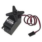


 工商网监
湘ICP备2023018690号
工商网监
湘ICP备2023018690号
