Techcode®
DATASHEET
60V, 2A, 480kHz Non-synchronous Buck Converter
General Description
Features
The TD1688 is a monolithic, step‐down, switch mode converter
with a built‐in power MOSFET. It achieves a 2A peak‐output
current over input supply 10V‐60V with excellent load and line
regulation. Current‐mode operation provides a fast transient
response and eases loop stabilization. Fault condition
protections include cycle‐by‐cycle current limiting and thermal
shutdown.
The TD1688 requires a minimal number of readily‐available
external components.
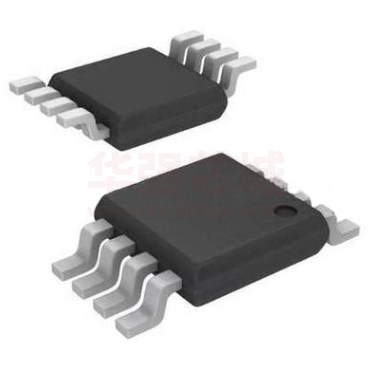
The TD1688 is available in a ESOP‐8 package.
Pin Configurations
Applications
TD1688
2A Peak Output Current
0.7Ω Internal Power MOSFET
Stable with Low‐ESR Ceramic Output Capacitors
Up to 91% Efficiency
0.1μA Shutdown Mode
Fixed 480kHz Frequency
Thermal Shutdown
Cycle‐by‐Cycle Over‐Current Protection
11V to 60V Operating Input Range
Max duty 90%
Available in a ESOP‐8 Package
Power Meters
Distributed Power Systems
Battery Chargers
Pre‐Regulator for Linear Regulators
WLED Drivers
(Top view)
March 4, 2019. Techcode Semiconductor Limited www.techcodesemi.com
1
�Techcode®
DATASHEET
60V, 2A, 480kHz Non-synchronous Buck Converter
TD1688
Pin Description
Pin Number
Pin Name
Description
1
SW
Power Switching Output. It is the Drain of the N‐Channel power MOSFET to supply power to
the output LC filter.
2
EN
On/Off. Pull EN above 1.35V to turn the device ON. For automatic enable, connect to VIN using
a 1MΩ resistor.
3
NC
Not connected
4
FB
Feedback. Sets the output voltage. Connect to the tap of an external resistor divider from the
output to GND. The frequency foldback comparator lowers the oscillator frequency when the
FB voltage is below 300mV to prevent current‐limit runaway during a short‐circuit fault.
Ground. Voltage reference for the regulated output voltage. Requires special layout
considerations. Isolate this node from the D1 to C1 ground path to prevent switching current
spikes from inducing.
5
GND
6
NC
Not connected
7
VIN
Supply Voltage. The TD1688 operates from a 10V‐to‐60V unregulated input. Requires C1 to
prevent large voltage spikes from appearing at the input.
8
BST
Bootstrap. Connect a capacitor between the SW and BS pins to form a floating supply across
the power switch driver. This capacitor drives the power switch’s gate above the supply
voltage.
9(Exposed
Pad)
GND
Thermal Pad. Connect this pad to the system ground plan for good thermal conductivity.
Ordering Information
TD1688
□
□
Circuit Type Packing:
Blank:Tube
Package
R: Tape and Reel
M:ESOP-8
March 4, 2019. Techcode Semiconductor Limited www.techcodesemi.com
2
�Techcode®
DATASHEET
60V, 2A, 480kHz Non-synchronous Buck Converter
TD1688
Function Block
Figure1 Function Block Diagram of TD1688
Absolute Maximum Ratings (Note1)
Symbol
Parameter
Rating
Unit
VIN
VIN Supply Voltage(VIN to Gnd)
‐0.3 ~ 60
V
VSW
SW to GND Voltage
‐0.3 to VIN+0.3
V
VBS
BS to GND Voltage
VSW ‐ 0.3 ~ VSW +6
V
All Other Pins
P D
Power Dissipation
θJA
Junction‐to‐Ambient Resistance in free air
TJ
Junction Temperature
TSTG
Storage Temperature
TSDR
‐0.3 ~ 6
Internally Limited
(Note 2)
Maximum Lead Soldering Temperature (10 Seconds)
V
W
50
°C/W
150
ºC
‐65 ~ 150
260
ºC
ºC
Note1: Stresses beyond those listed under "absolute maximum ratings" may cause permanent damage to the device. These are stress ratings only and functional
operation of the device at these or any other conditions beyond those indicated under "recommended operating conditions" is not implied. Exposure to absolute
maximum rating conditions for extended periods may affect device reliability.
Note 2: θJA is measured with the component mounted on a high effective thermal conductivity test board in free air.
March 4, 2019. Techcode Semiconductor Limited www.techcodesemi.com
3
�Techcode®
DATASHEET
60V, 2A, 480kHz Non-synchronous Buck Converter
TD1688
Recommended Operation Conditions (Note3)
Symbol
Parameter
VIN
VIN Supply Voltage
VOUT
Converter Output Voltage
Range
Unit
11 ~ 60
V
VFB ~ VIN*90%
Operating Junction Temp
V
o
C
‐40 ~ 125
Note 3: Refer to the typical application circuit
Electrical Characteristics
Unless otherwise specified, these specifications apply over VIN=12V, VEN=3V and TA = 25ºC.
Symbol
Parameter
Test Conditions
Min
Typ
0.792
0.812
VFB
Feedback Voltage
10V ≤ VIN ≤ 60V
IFB
Feedback Current
VFB = 0.85V
‐
‐
RDS(ON) Switch‐On Resistance
‐
ISW_LKG Switch Leakage
VEN=0V,VSW=0V
Max
Unit
0.832
V
0.1
µA
0.7
‐
Ω
‐
‐
1
µA
‐
2.8
‐
A
380
480
580
kHZ
ILIM
Current Limit
fSW
Oscillator Frequency
VFB=0.6V
fSW_F
Foldback Frequency
VFB=0V
‐
120
‐
KHZ
DMAX
Maximum Duty Cycle
VFB=0.6V
‐
90
‐
%
TON
Minimum ON‐Time
‐
100
‐
ns
VUVLO_R
Under‐Voltage Lockout
Threshold, Rising
‐
7.5
8.5
V
VUVLO_F
Under‐Voltage Lockout
Threshold, Falling
‐
7.1
‐
V
VUVLO_HYS
Under‐Voltage Lockout
Threshold,Hysteresis
‐
0.4
‐
V
VEN_R
EN Threshold, Rising
‐
1.35
‐
V
VEN_F
EN Threshold, Falling
‐
1.17
‐
V
‐
180
‐
mv
VEN=2V
‐
3.1
‐
µA
VEN=0V
‐
0.1
‐
µA
VEN_HYS EN Threshold, Hysteresis
IEN
EN Input Current
I S
Supply Current (Shutdown)
VEN=0V
‐
0.1
1
µA
I Q
Supply Current (Quiescent)
VEN=2V,VFB=1V
‐
0.73
0.85
TSD
Thermal Shutdown
‐
165
‐
mA
o
C
TSD_HYS Thermal Shutdown Hysteresis
‐
20
‐
March 4, 2019. Techcode Semiconductor Limited www.techcodesemi.com
4
C
o
�Techcode®
DATASHEET
60V, 2A, 480kHz Non-synchronous Buck Converter
TD1688
Typical Application Circuit
C3
U1
1
7
VIN
0.1uF
BST
L1
33uH
SW
VIN
NC
R3
1M
12V
8
6
VOUT
D1
SS36
C2
22uF
TD1688
EC1
C1
1uF
R2
150K
9
3
GND
FB
GND
EN
NC
2
5
100uF
4
R1
11K
R4
C4
NC
NC
OPERATION
The TD1688 is a current mode buck regulator. That is, the EA output voltage is proportional to the peak inductor current.
At the beginning of a cycle, M1 is off. The EA output voltage is higher than the current sense amplifier output, and the current
comparator’s output is low. The rising edge of the 480kHz CLK signal sets the RS Flip‐Flop. Its output turns on M1 thus
connecting the SW pin and inductor to the input supply.
The increasing inductor current is sensed and amplified by the Current Sense Amplifier. Ramp compensation is summed to the
Current Sense Amplifier output and compared to the Error Amplifier output by the PWM Comparator. When the sum of the
Current Sense Amplifier output and the Slope Compensation signal exceeds the EA output voltage, the RS Flip‐Flop is reset and
M1 is turned off. The external Schottky rectifier diode (D1) conducts the inductor current.
If the sum of the Current Sense Amplifier output and the Slope Compensation signal does not exceed the EA output for a
whole cycle, then the falling edge of the CLK resets the Flip‐Flop.
The output of the Error Amplifier integrates the voltage difference between the feedback and the 0.812V bandgap reference.
The polarity is such that lower than 0.812V FB pin voltage increases the EA output voltage. Since the EA output voltage is
proportional to the peak inductor current, an increase in its voltage also increases current delivered to the output.
March 4, 2019. Techcode Semiconductor Limited www.techcodesemi.com
5
�Techcode®
DATASHEET
60V, 2A, 480kHz Non-synchronous Buck Converter
TD1688
Application Information
Setting Output Voltage
The external resistor divider sets the output voltage (see the
Typical Application schematic). Table 1 lists resistors for
common output voltages. The feedback resistor (R2) also
sets the feedback loop bandwidth with the internal
compensation capacitor (see Figure 1). R1 is:
R1 =
R2
V
−1
0.812V
Table 1:Resistor Selection for Common output voltages
VOUT(V)
R1(KΩ)
R2(KΩ)
1.8
102(1%)
124(1%)
2.5
59(1%)
124(1%)
3.3
40.2(1%)
124(1%)
5
23.7(1%)
124(1%)
Selecting the Inductor
Use an inductor with a DC current rating at least 25%
percent higher than the maximum load current for most
applications. For best efficiency, the inductor’s DC resistance
should be less than 200mΩ.
For most designs, the required inductance value can be
derived from the following equation.
V
× (V − V )
L=
V × ∆I × f
Where ΔIL is the inductor ripple current.
Choose the inductor ripple current to be 30% of the
maximum load current. The maximum inductor peak current
is:
∆I
2
Under light‐load conditions (below 100mA), use a larger
inductance to improve efficiency.
Selecting the Input Capacitor
The input capacitor reduces the surge current drawn from
the input supply and the switching noise from the device.
The input capacitor impedance at the switching frequency
I
(
)
=I
+
should be less than the input source impedance to prevent
high‐frequency‐switching current from passing through the
input. Use ceramic capacitors with X5R or X7R dielectrics for
their low ESRs and small temperature coefficients. For most
applications, a 4.7μF capacitor will sufficient.
Selecting the Output Capacitor
The output capacitor keeps the output voltage ripple small
and ensures feedback loop stability. The output capacitor
impedance should be low at the switching frequency. Use
ceramic capacitors with X5R or X7R dielectrics for their low
ESR characteristics. For most applications, a 22μF ceramic
capacitor will sufficient.
PCB Layout Guide
PCB layout is very important to stability. Please follow these
guidelines.
1) Keep the path of switching current short and minimize
the loop area formed by the input capacitor, high‐side
MOSFET, and Schottky diode.
2) Keep the connection from the power ground→Schottky
diode→SW pin as short and wide as possible.
3) Ensure all feedback connections are short and direct.
Place the feedback resistors and compensation components
as close to the chip as possible.
4) Route SW away from sensitive analog areas such as FB.
5) Connect IN, SW, and especially GND to large copper areas
to cool the chip for improved thermal performance and
long‐ term reliability. For single layer PCBs, avoid soldering
the exposed pad.
March 4, 2019. Techcode Semiconductor Limited www.techcodesemi.com
6
�Techcode®
60V, 2A, 480kHz Non-synchronous Buck Converter
DATASHEET
TD1688
Package Information
ESOP‐8 Package Outline Dimensions
March 4, 2019. Techcode Semiconductor Limited www.techcodesemi.com
7
�Techcode®
DATASHEET
60V, 2A, 480kHz Non-synchronous Buck Converter
TD1688
Design Notes
March 4, 2019. Techcode Semiconductor Limited www.techcodesemi.com
8
�


 工商网监
湘ICP备2023018690号
工商网监
湘ICP备2023018690号

