UMW
R
UMW TLP185
1. Applications
•
Office Equipment
•
Programmable Logic Controllers (PLCs)
•
AC Adapters
•
I/O Interface Boards
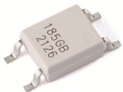
2. General
The UMW TLP185 consist of a photo transistor optically coupled to gallium arsenide infrared emitting
diode. The UMW TLP185 photocoupler is housed in the very small and thin SO6 package.
Since UMW TLP185 is smaller than DIP package, it's suitable for high-density surface mounting
application such as programmable controllers.
3. Features
(1)
(2)
Collector-emitter voltage: 80 V (min)
Current transfer ratio: 50% (min)
Rank GB: 100% (min)
(3)
Isolation voltage: 3750 Vrms (min)
(4)
(5)
Operating temperature: -55 to 110
Safety standards
UL-approved: UL1577, File No.E492440
4. Packaging and Pin Assignment
1: Anode
3: Cathode
4: Emitter
6: Collector
www.umw-ic.com
1
友台半导体有限公司
�UMW
R
UMW TLP185
5. Principle of Operation
5.1. Mechanical Parameters
Characteristics
Min
Unit
Creepage distances
5.0
mm
Clearance
5.0
Internal isolation thickness
0.4
6. Absolute Maximum Ratings (Note) (Unless otherwise specified, Ta = 25 )
Symbol
Characteristics
LED
Input forward current
Input forward current derating
(Ta ≥ 90 )
50
mA
-1.5
mA/
1
A
5
V
IFP
VR
(Ta ≥ 90 )
Unit
IF
Input reverse voltage
Input power dissipation
derating
Rating
∆IF/∆Ta
Input forward current (pulsed)
Input power dissipation
Note
(Note 1)
PD
100
mW
∆PD/∆Ta
-2.86
mW/
Tj
125
Detector Collector-emitter voltage
VCEO
80
V
Emitter-collector voltage
VECO
7
V
IC
50
mA
Junction temperature
Collector current
Collector power dissipation
Collector power dissipation
derating
(Ta ≥ 25 )
Junction temperature
Common Operating temperature
Storage temperature
Lead soldering temperature
(10 s)
Total power dissipation
Isolation voltage
Note:
AC, 60 s, R.H. ≤ 60%
PC
150
mW
∆PC/∆Ta
-1.5
mW/
Tj
125
Topr
-55 to 110
Tstg
-55 to 125
Tsol
260
PT
200
mW
3750
Vrms
BVS
(Note 2)
Using continuously under heavy loads (e.g. the application of high temperature/current/voltage and the
significant change in temperature, etc.) may cause this product to decrease in the reliability significantly even
if the operating conditions (i.e. operating temperature/current/voltage, etc.) are within the absolute maximum
ratings.
Note 1: Pulse width (PW) ≤ 100 µs, f = 100 Hz
Note 2: This device is considered as a two-terminal device: Pins 1 and 3 are shorted together, and pins 4 and 6 are
shorted together.
www.umw-ic.com
2
友台半导体有限公司
�UMW
R
UMW TLP185
7. Electrical Characteristics (Unless otherwise specified, Ta = 25 )
Symbol
Characteristics
LED
Note
Test Condition
Min
Typ.
Max
Unit
Input forward voltage
VF
IF = 10 mA
1.1
1.25
1.4
V
Input reverse current
IR
VR = 5 V
5
µA
Input capacitance
Ct
V = 0 V, f = 1 MHz
30
pF
Detector Collector-emitter breakdown
voltage
V(BR)CEO
IC = 0.5 mA
80
V
Emitter-collector breakdown
voltage
V(BR)ECO
IE = 0.1 mA
7
Dark Current
IDARK
VCE = 48 V
0.01
0.08
VCE = 48 V, Ta = 85
2
50
Collector-emitter capacitance
CCE
V = 0 V, f = 1 MHz
10
pF
µA
8. Coupled Electrical Characteristics (Unless otherwise specified, Ta = 25 )
Characteristics
Current transfer ratio
Symbol
Note
IC/IF
(Note 1)
Saturated current transfer ratio
IC/IF(sat)
Collector-emitter saturation
voltage
VCE(sat)
OFF-state collector current
IC(off)
Min
Typ.
Max
Unit
IF = 5 mA, VCE = 5 V
50
600
%
IF = 5 mA, VCE = 5 V, Rank GB
Test Condition
100
600
IF = 1 mA, VCE = 0.4 V
60
IF = 1 mA, VCE = 0.4 V, Rank GB
30
IC = 2.4 mA, IF = 8 mA
0.3
IC = 0.2 mA, IF = 1 mA
0.2
IC = 0.2 mA, IF = 1 mA, Rank GB
0.3
VF = 0.7 V, VCE = 48 V
1
10
V
µA
Note 1: See Table 8.1 for current transfer ratio.
Table 8.1 Current Transfer Ratio (CTR) Rank (Note) (Unless otherwise specified, Ta = 25 )
Current
transfer ratio
IC/IF
Min
Current
transfer ratio
IC/IF
Max
50
600
Y
50
150
YE, Y+
GR
100
300
GR, G, G+
GB
100
600
GB, GR, BL, G, G+, B
BL
200
600
BL, B
YH
75
150
Y+
GRL
100
200
G
GRH
150
300
G+
BLL
200
400
B
Rank
IF = 5 mA, VCE = 5 V
Blank
Note:
Test Condition
Marking of
Classification
Blank, YE, GR, GB,
BL, Y+, G, G+, B
Unit
%
Specify both the part number and a rank in this format when ordering.
Example: UMW TLP185GB
www.umw-ic.com
3
友台半导体有限公司
�UMW
R
UMW TLP185
9. Isolation Characteristics (Unless otherwise specified, Ta = 25 )
Characteristics
Symbol
Note
Test Condition
Min
Typ.
Max
Unit
0.8
pF
1 × 10¹²
1014
Ω
3750
Vrms
AC, 1 s in oil
10000
DC, 60 s in oil
10000
Total capacitance (input to
output)
CS
(Note 1) VS = 0 V, f = 1 MHz
Isolation resistance
RS
(Note 1) VS = 500 V, R.H. ≤ 60%
Isolation voltage
BVS
(Note 1) AC, 60 s
Vdc
Note 1: This device is considered as a two-terminal device: Pins 1 and 3 are shorted together, and pins 4 and 6 are
shorted together.
10. Switching Characteristics (Unless otherwise specified, Ta = 25 )
Characteristics
Rise time
Fall time
Symbol
tr
tf
Turn-on time
ton
Turn-off time
toff
Turn-on time
ton
Storage time
ts
Turn-off time
toff
Note
Test Condition
VCC = 10 V, IC = 2 mA,
RL = 100 Ω
See Fig. 10.1
VCC = 5 V, IF = 16 mA,
RL = 1.9 kΩ
Min
Typ.
Max
Unit
2
µs
3
3
3
0.5
25
40
Fig. 10.1 Switching Time Test Circuit and Waveform
www.umw-ic.com
4
友台半导体有限公司
�UMW
R
UMW TLP185
11. Characteristics Curves (Note)
Fig. 11.1 IF - Ta
Fig. 11.2 PC - Ta
Fig. 11.3 IFP - DR
Fig. 11.4 IF - VF
Fig. 11.5 ∆VF/∆Ta - IF
Fig. 11.6 IFP - VFP
www.umw-ic.com
5
友台半导体有限公司
�UMW
R
UMW TLP185
Fig. 11.7 IC - VCE
Fig. 11.8 IC - VCE
Fig. 11.9 IC - IF
Fig. 11.10 IC/IF - IF
Fig. 11.11 IDARK - Ta
Fig. 11.12 VCE(sat) - Ta
www.umw-ic.com
6
友台半导体有限公司
�UMW
R
UMW TLP185
Fig. 11.13 IC - Ta
Fig. 11.14 Switching Time - RL
Fig. 11.15 Switching Time - Ta
Note:
The above characteristics curves are presented for reference only and not guaranteed by production test,
unless otherwise noted.
www.umw-ic.com
7
友台半导体有限公司
�UMW
R
UMW TLP185
12. Soldering and Storage
12.1. Precautions for Soldering
The soldering temperature should be controlled as closely as possible to the conditions shown below, irrespective
of whether a soldering iron or a reflow soldering method is used.
•
When using soldering reflow.
The soldering temperature profile is based on the package surface temperature.
(See the figure shown below, which is based on the package surface temperature.)
Reflow soldering must be performed once or twice.
The mounting should be completed with the interval from the first to the last mountings being 2 weeks.
Fig. 12.1.1 An Example of a Temperature Profile When Lead(Pb)-Free Solder Is Used
•
When using soldering flow
Preheat the device at a temperature of 150 (package surface temperature) for 60 to 120 seconds.
Mounting condition of 260 within 10 seconds is recommended.
Flow soldering must be performed once.
•
When using soldering Iron
Complete soldering within 10 seconds for lead temperature not exceeding 260 or within 3 seconds not
exceeding 350
Heating by soldering iron must be done only once per lead.
12.2. Precautions for General Storage
•
Avoid storage locations where devices may be exposed to moisture or direct sunlight.
•
Follow the precautions printed on the packing label of the device for transportation and storage.
•
Keep the storage location temperature and humidity within a range of 5 to 35 and 45 % to 75 %,
•
Do not store the products in locations with poisonous gases (especially corrosive gases) or in dusty
•
Store the products in locations with minimal temperature fluctuations. Rapid temperature changes during
respectively.
conditions.
storage can cause condensation, resulting in lead oxidation or corrosion, which will deteriorate the
solderability of the leads.
•
When restoring devices after removal from their packing, use anti-static containers.
•
Do not allow loads to be applied directly to devices while they are in storage.
•
If devices have been stored for more than two years under normal storage conditions, it is recommended
that you check the leads for ease of soldering prior to use.
www.umw-ic.com
8
友台半导体有限公司
�


 工商网监
湘ICP备2023018690号
工商网监
湘ICP备2023018690号

