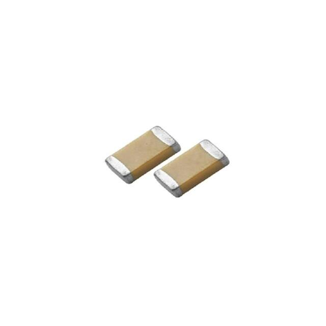
Multilayer Ceramic Chip Capacitors
High Voltage Type ≥1KV
HC Series
FEATURE
High voltage rating in a given case size.
High reliability and thermal stability.
Application: DC to DC converter, High Voltage Coupling/DC blocking,
Back-lighting inverters, LAN/WLAN interface, Power supplies, Snubbers
in HF power convertors.
PART NUMBERING SYSTEM
HC
1812
XR
822
K
102
(1)
(2)
(3)
(4)
(5)
(6)
No
Item
(1)
Meritek Series
(2)
Size
(3)
Dielectric
Digit
Description
HC
1812
XR
(4)
Capacitance
(5)
Tolerance
(6)
Rated Voltage
RoHS
Reference
High-Voltage Ceramic Chip Capacitor
High voltage application with ≧ 1KVdc
1812 inch (4532 mm)
0805,1206,1210,1808, 1825,2211,2220,2225
X7R
CG: C0G(NP0), XR: X7R, XF: X5R, YV: Y5V
822: 82x10 pF = 8200pF
103: 10x103pF, 4R7: 4.7pF
(K): ±10%
F: ±1%,G: ±2%,J: ±5%,K: ±10%,M: ±20%
Working Voltage: 1000VDC
152: 1.5KVDC, 202: 2.0KVDC, 3KVDC, 4KVDC
2
822
K
102
DIMENSIONS
Thickness
Size Inch
(mm)
L (mm)
W (mm)
0603 (1608)
1.60±0.20
0.80±0.15
0.40±0.15
0805 (2012)
2.10±0.20
1.25±0.20
0.50±0.20
1206 (3216)
3.30±0.30
1.60+0.30/-0.10
1210 (3225)
3.30±0.40
2.50±0.30
1808 (4520)
4.60±0.50
2.00±0.20
1812 (4532)
4.60±0.50
3.20±0.30
1825 (4563)
4.60±0.50
6.30±0.40
2220 (5750)
5.70±0.50
5.00±0.40
0.85±0.35
2225 (5763)
5.70±0.50
6.30±0.40
0.85±0.35
T (mm) code
See
Thickness
Specification
Reference
Table
below
MB min (mm)
0.60±0.20
0.75±0.35
0.75±0.35
0.75±0.35
0.75±0.35
THICKNESS SPECIFICATION REFERENCE
Code
A
B
C
D
E
F
G
H
Thickness (mm)
0.60 ± 0.10
0.8 + 0.15/-0.10
1.25 ± 0.10
1.40 ± 0.15
1.60 ± 0.20
2.00 ± 0.20
2.50 ± 0.30
2.80 ± 0.30
Code
I
J
K
L
M
N
O
P
Thickness (mm)
1.25 ± 0.20
1.15 ± 0.15
0.50 ± 0.20
0.30 ± 0.03
0.95 ± 0.10
0.50 ± 0.05
3.50 ± 0.20
1.60 +0.3/-0.10
Code
Q
R
S
T
U
V
X
Z
Thickness (mm)
0.50 + 0.02/-0.05
3.10 ± 0.30
0.80 ± 0.07
0.85 ± 0.10
0.50 ± 0.10
0.20 ± 0.02
0.80 ± 0.10
0.25 ± 0.03
Rev. 7d
�Multilayer Ceramic Chip Capacitors
High Voltage Type ≥1KV
HC Series
ELECTRICAL CHARACTERISTICS
Properties
Characteristics
Dielectric
C0G(NP0)
X7R
Size
0805, 1206, 1210, 1808,
1812, 1825, 2220, 2225
0603, 0805, 1206, 1210,1808,
1812, 1825, 2220, 2225
Rated Voltage
1KV, 1.5KV, 2KV, 3KV,4KV
1KV, 1.5KV, 2KV, 3KV,4KV
Capacitance
Range
0.5pF ~ 12nF
100pF ~ 330nF
Capacitance Tolerance
See Capacitance Tolerance ReferenceTable Below
Cap. Range
Cap < 30pF
Cap ≥ 30pF
Dissipation
Factor
Q Spec.
Q ≥ 400+20C
Q ≥ 1000
≤2.5%
Measured at the condition of 30~70% related humidity.
Preconditioning : Preform a heat treatment at 150±10⁰C
for an hour, then leave in ambient condition for 24±2
hours before measurement
For 25⁰C at ambient temperature
Cap. & D.F. Test Condition
(30~70% Relative Humidity)
Cap. Range
Cap≤1000pF
Cap>1000pF
Test Condition
1.0±0.2Vrms,
1.0MHz±10%
1.0±0.2Vrms,
1.0KHz±10%
1.0±0.2Vrms, 1.0KHz±10%,
at 25⁰C ambient temperature
≥100GΩ or RC≥5000Ω-F
Whichever is smaller
Insulation Resistance
Operation Temperature
≥10GΩ or RC≥100Ω-F
Whichever is smaller
-55°C ~ +125°C
Temperature Coefficient
±15%
±30ppm/⁰C
Termination
Cu (or Ag)/Ni/Sn (lead-free)
CAPACITANCE TOLERANCE REFERENCE
Code
Description
Code
Description
Code
Description
Code
Description
A
±0.05 pF
F
±1 %
J
±5 %
N
-5%~10%
B
±0.10 pF
G
±2 %
K
±10 %
P
±0.02 pF
C
±0.25 pF
H
±3 %
L
0%~10%
Q
±0.03 pF
D
±0.50 pF
I
-10%~0%
M
±20 %
Z
-20%~80%
Rev. 7d
�Multilayer Ceramic Chip Capacitors
High Voltage Type ≥1KV
HC Series
RELIABILITY TEST CONDITIONS AND REQUIREMENTS
Item
Visual and
Dimensions
Test Condition
Requirements
No remarkable defect.
Dimensions to confirm to individual specification sheet.
---
Shall not exceed the limits given in the detailed spec.
Capacitance
Q/ D.F.
(Dissipation
Factor)
Temperature
Coefficient
Class I: C0G(NP0)
Cap≤1000pF, 1.0±0.2Vrms, 1MHz±10%
Cap>1000pF, 1.0±0.2Vrms, 1KHz±10%
Class II: (X7R)
1.0±0.2Vrms, 1kHz±10%
With no electrical load.
T.C.
C0G(NP0)
X7R
Dielectric
Operation Temp.
-55~125°C at 25°C
-55~125°C at 25°C
To apply voltage at 500VDC for 60 sec.
Insulation
Resistance
Solderability
Dielectric
Strength
Solder temperature: 235±5°C for (1206~1210)
Solder temperature: 245±5°C for (1808~2225)
Dipping time: 2±0.5 sec.
Resistance
to
Soldering Heat
Temperature
Cycle
Conduct the five cycles according to the temperatures
and time.
Step
Temp. (°C)
Time (min.)
1
Min. operating temp. +0/-3
30±3
2
Room temp.
2~3
3
Max. Operating temp. +3/-0
30±3
4
Room temp.
2~3
Before initial measurement (Class II only): Perform
150+0/-10°C for 1 hr and then set for 48±4 hrs at room
temp.
Measurement to be made after keeping at room temp.
for 24±2 hrs (Class I) or 48±4 hrs (Class II).
Vibration
Resistance
Vibration frequency: 10~55 Hz/min.
Total amplitude: 1.5mm
Test time: 6 hrs. (Two hrs. each in three mutually
perpendicular directions.)
Class I(NP0)
All
Class II(X7R)
≥ 100
Q/D.F.
Remark
Q≥1000
Q≥400+20C
D.F. < 2.5%
D.F. < 3.0%
Cap≥30pF
Cap


 工商网监
湘ICP备2023018690号
工商网监
湘ICP备2023018690号
