TFCR0805-8W-E-3011BT 数据手册
TFCR
SERIES
PRECISION THIN FILM RESISTORS
FEATURES:
• TCR as low as ±25ppm
• Higher operating frequency with less parasitics
• Noise characteristics superior to standard thick film resistors
• Reference standards of EIA JIS C 5201-1
• Tolerance as low as ±0.1%
PART NUMBER STRUCTURE
TFCR
1206
Series
Size
0201
0402
0603
0805
1206
1210
2010
2512
-
8W
-
E
Power Rating
32W = 0.03W
20W = 0.05W
16W = 0.063W
10W = 0.10W
8W = 0.125W
4W = 0.25W
2W = 0.50W
-
TCR
E = ±25ppm/˚C
C = ±50ppm/˚C
K = ±100ppm/˚C
1001
B
T
M
Resistance Value
1001 = 1KΩ
4 digit code e.g.
4R70 = 4.7Ω
1001 = 1KΩ
2494 = 2.49MΩ
Resistance Tolerance
B = ±0.1%
C = ±0.25%
D = ±0.50%
F = ±1%
Packaging
T = Tape &
Reel
Optional Reel Identifier
Leave blank for standard
quantity.
Example P/N: TFCR1206-8W-E-1001BT
Add "-1K" if 1000 piece reel
is required
Standard Termination is 100% matte Tin over Nickel.
DIMENSIONS
Unit: inches (mm)
L
W
ι1
ι1
T
ι2
ι2
SIZE
L
W
T
i1
i2
0201
0.023 ± 0.001
(0.60 ± 0.03)
0.011 ± 0.001
(0.30 ± 0.03)
0.009 ± 0.001
(0.23 ± 0.03)
0.006 ± 0.002
(0.15 ± 0.05)
0.006 ± 0.002
(0.15 ± 0.05)
0402
0.040 ± 0.002
(1.0 ± 0.05)
0.019 ± 0.002
(0.5 ± 0.05)
0.012 ± 0.002
(0.30 ± 0.05)
0.008 ± 0.004
(0.2 ± 0.10)
0.008 ± 0.004
(0.2 ± 0.10)
0603
0.061 ± 0.004
(1.55 ± 0.10)
0.031 ± 0.004
(0.8 ± 0.1)
0.018 ± 0.004
(0.45 ± 0.10)
0.012 ± 0.008
(0.30 ± 0.20)
0.012 ± 0.008
(0.30 ± 0.20)
0805
0.079 ± 0.006
(2.0 ± 0.15)
0.049± 0.006
(1.25 ± 0.15)
0.022 ± 0.004
(0.55 ± 0.10)
0.012 ± 0.008
(0.30 ± 0.20)
0.016 ± 0.010
(0.40 ± 0.25)
1206
0.120 ± 0.006
(3.05 ± 0.15)
0.061 ± 0.006
(1.55 ± 0.15)
0.022 ± 0.004
(0.55 ± 0.10)
0.017 ± 0.008
(0.42 ± 0.20)
0.014 ± 0.010
(0.35 ± 0.25)
1210
0.122 ± 0.006
(3.10 ± 0.15)
0.094 ± 0.006
(2.40 ± 0.15)
0.022 ± 0.004
(0.55 ± 0.10)
0.016 ± 0.008
(0.40 ± 0.20)
0.022 ± 0.010
(0.55 ± 0.25)
2010
0.193 ± 0.006
(4.90 ± 0.15)
0.094 ± 0.006
(2.40 ± 0.15)
0.022 ± 0.004
(0.55 ± 0.10)
0.024 ± 0.012
(0.60 ± 0.30)
0.020 ± 0.010
(0.50 ± 0.25)
2512
0.248 ± 0.006
(6.30 ± 0.15)
0.122 ± 0.006
(3.10 ± 0.15)
0.022 ± 0.004
(0.55 ± 0.10)
0.024 ± 0.012
(0.60 ± 0.30)
0.020 ± 0.010
(0.50 ± 0.25)
STRUCTURE
3
8
4
1
6
7
9
5
1
Alumina Substrate
5
Nickel Plating
2
Backside Electrode
6
Tin Plating
3
Top Electrode
7
Resistive layer
4
Edge Electrode
8
Overcoat
2
1
Email: sales@venkel.com
|
Phone: 512.794.0081 |
Toll Free: 800.950.8365 |
Web: www.venkel.com
Rev: 01/2021-A
1
�TFCR
SERIES
PRECISION THIN FILM RESISTORS
ELECTRICAL SPECIFICATION & RANGE
SIZE
0201
Power Rating
at 70°C (W)
0.03W
(1/32W)
0402
0.05W
(1/20W)
0603
0.063W
(1/16W)
0.063W
(1/16W)
0805
0.10W
(1/10W)
0.10W
(1/10W)
0.125W
(1/8W)
1206
0.125W
(1/8W)
0.25W
(1/4W)
1210
2010
2512
0.25W
(1/4W)
0.25W
(1/4W)
0.50W
(1/2W)
Max. Working
Voltage
15V
25V
50V
100V
150V
150V
150V
150V
Max. Overload
Voltage
30V
50V
100V
200V
300V
300V
300V
300V
Operating
Temp. Range
-55°C
to +125°C
-55°C
to +155°C
-55°C
to +155°C
-55°C
to +155°C
-55°C
to +155°C
-55°C
to +155°C
-55°C
to +155°C
-55°C
to +155°C
Tolerance
TCR
Resistance Range
Resistance
Range
Resistance
Range
Resistance
Range
Resistance
Range
Resistance
Range
±25ppm
100Ω - 10KΩ 100Ω - 12KΩ
10Ω - 511KΩ
4.7Ω - 1MΩ
4.7Ω - 2MΩ 4.7Ω - 1MΩ 4.7Ω - 2.49MΩ 4.7Ω - 1MΩ 4.7Ω - 2.49MΩ 4.7Ω - 3MΩ 4.7Ω - 3MΩ
±0.1%
(B)
±50ppm
100Ω - 10KΩ 100Ω - 12KΩ
10Ω - 511KΩ
4.7Ω - 1MΩ
4.7Ω - 2MΩ 4.7Ω - 1MΩ 4.7Ω - 2.49MΩ 4.7Ω - 1MΩ 4.7Ω - 2.49MΩ 4.7Ω - 3MΩ 4.7Ω - 3MΩ
±100ppm
100Ω - 10KΩ
-
10Ω - 511KΩ
4.7Ω - 1MΩ
4.7Ω - 2MΩ 4.7Ω - 1MΩ 4.7Ω - 2.49MΩ 4.7Ω - 1MΩ 4.7Ω - 2.49MΩ 4.7Ω - 3MΩ 4.7Ω - 3MΩ
±25ppm
100Ω - 10KΩ
-
4.7Ω - 511KΩ 1Ω - 1MΩ 4.7Ω - 1MΩ
±0.25%
(C)
±0.5%
(D)
1Ω - 1MΩ
1Ω - 2.49MΩ
4.7Ω - 1MΩ
1Ω - 2.49MΩ
1Ω - 3MΩ
1Ω - 3MΩ
±50ppm
100Ω - 10KΩ
-
4.7Ω - 511KΩ 1Ω - 1MΩ 4.7Ω - 1MΩ
1Ω - 2MΩ
1Ω - 1MΩ
1Ω - 2.49MΩ
4.7Ω - 1MΩ
1Ω - 2.49MΩ
1Ω - 3MΩ
1Ω - 3MΩ
±100ppm
100Ω - 10KΩ
-
4.7Ω - 511KΩ 1Ω - 1MΩ 4.7Ω - 1MΩ
1Ω - 2MΩ
1Ω - 1MΩ
1Ω - 2.49MΩ
4.7Ω - 1MΩ
1Ω - 2.49MΩ
1Ω - 3MΩ
1Ω - 3MΩ
±25ppm
-
27Ω - 12KΩ
4.7Ω - 511KΩ 1Ω - 1MΩ 4.7Ω - 1MΩ
1Ω - 2MΩ
1Ω - 1MΩ
1Ω - 2.49MΩ
4.7Ω - 1MΩ
1Ω - 2.49MΩ
1Ω - 3MΩ
1Ω - 3MΩ
±50ppm
49.9Ω-33KΩ 27Ω - 22.1KΩ 4.7Ω - 511KΩ 1Ω - 1MΩ 4.7Ω - 1MΩ
1Ω - 2MΩ
1Ω - 1MΩ
1Ω - 2.49MΩ
4.7Ω - 1MΩ
1Ω - 2.49MΩ
1Ω - 3MΩ
1Ω - 3MΩ
±100ppm
49.9Ω-33KΩ 27Ω - 22.1KΩ 4.7Ω - 511KΩ 1Ω - 1MΩ 4.7Ω - 1MΩ
1Ω - 2MΩ
1Ω - 1MΩ
1Ω - 2.49MΩ
4.7Ω - 1MΩ
1Ω - 2.49MΩ
1Ω - 3MΩ
1Ω - 3MΩ
1Ω - 2MΩ
1Ω - 1MΩ
1Ω - 2.49MΩ
4.7Ω - 1MΩ
1Ω - 2.49MΩ
1Ω - 3MΩ
1Ω - 3MΩ
±25ppm
±1% (F)
1Ω - 2MΩ
Resistance Resistance
Range
Range
-
27Ω - 12KΩ
4.7Ω - 511KΩ 1Ω - 1MΩ 4.7Ω - 1MΩ
±50ppm
49.9Ω-33KΩ 27Ω - 22.1KΩ 4.7Ω - 511KΩ 1Ω - 1MΩ 4.7Ω - 1MΩ
1Ω - 2MΩ
1Ω - 1MΩ
1Ω - 2.49MΩ
4.7Ω - 1MΩ
1Ω - 2.49MΩ
1Ω - 3MΩ
1Ω - 3MΩ
±100ppm
49.9Ω-33KΩ 27Ω - 22.1KΩ 4.7Ω - 511KΩ 1Ω - 1MΩ 4.7Ω - 1MΩ
1Ω - 2MΩ
1Ω - 1MΩ
1Ω - 2.49MΩ
4.7Ω - 1MΩ
1Ω - 2.49MΩ
1Ω - 3MΩ
1Ω - 3MΩ
NOTE: Max Working Voltage is listed above or √(P*R), whichever is lower. Max overload Voltage is listed above or 2.5*√(P*R), whichever is lower.
MARKING CODE
• �E-24 values for 0603 size maybe marked with the standard 3 digit marking
code.
• �E-96 values for 0805 size and larger, will be marked with standard 4 digit
marking code.
• �E-24 values for 0603 size and larger, will be marked with standard 3 digit
marking code.
• �0603 - E-96 values will be marked with a standard 3 digit alpha numeric code
Please see 0603 marking codes PDF.
Note: 0201 and 0402 cannot be marked.
DERATING CURVE
Rated power (%)
120
100
80
60
40
20
0
-50
-55
-25
0
25
50
75
100
70
Ambient temperature (˚C)
0201 Size
Email: sales@venkel.com
125
150
175
0402 to 2512 Size
|
Phone: 512.794.0081 |
Toll Free: 800.950.8365 |
Web: www.venkel.com
Rev: 01/2021-A
2
�TFCR
SERIES
PRECISION THIN FILM RESISTORS
REEL SPECIFICATIONS
F
Label
H
Unit: mm (inch)
M C
E
C
E
F
G
H
M
13.0 ± 0.2
(0.51 ± 0.008)
60.0 ± 1.0
(2.36 ± 0.03)
11.4 ± 1.0
(0.45 ± 0.04)
9.0 ± .3
(0.35 ± 0.012)
1.5 ± .3
(0.06 ± 0.012)
180 ± 2.0
(7.09 ± 0.08)
Minimum of 30 empty pockets at the beginning of reel, 65 minimum empty pockets at the end.
G
TAPE SPECIFICATIONS
T
G
B
A
W
F
T
J
Dø
Embossed
H
Paper
E
Units: mm
TAPE
SIZE (in)
A
B
W
E
F
T
G
H
J
Dø
0201
0.70±0.05
0.40±0.05
8.0±0.10
1.75±0.05
3.50±0.05
0.42±0.02
2.00±0.05
4.00±0.10
2.00±0.05
1.55±0.03
0402
1.16±0.10
0.70±0.10
8.0±0.10
1.75±0.05
3.50±0.05
0.40±0.03
2.00±0.05
4.00±0.10
2.00±0.05
1.55±0.05
0603
1.90±0.10
1.10±0.05
8.0±0.10
1.75±0.05
3.50±0.05
0.60±0.03
4.00±0.10
4.00±0.10
2.00±0.05
1.55±0.05
0805
2.37±0.20
1.60±0.05
8.0±0.10
1.75±0.05
3.50±0.05
0.75±0.05
4.00±0.10
4.00±0.10
2.00±0.05
1.55±0.05
1206
3.55±0.05
2.00±0.05
8.0±0.10
1.75±0.05
3.50±0.05
0.75±0.05
4.00±0.10
4.00±0.10
2.00±0.05
1.55±0.05
1210
3.40±0.05
2.75±0.05
8.0±0.10
1.75±0.05
3.50±0.05
0.75±0.05
4.00±0.10
4.00±0.10
2.00±0.05
1.60±0.10
2010
5.45±0.10
2.85±0.10
12.00±0.10
1.75±0.10
5.50±0.05
1.00 +0.20, -0
4.00±0.10
4.00±0.10
2.00±0.05
1.50 +0.1, -0
2512
6.65±0.10
3.40±0.10
12.00±0.10
1.75±0.10
5.50±0.05
1.00 +.02.0, -0
4.00±0.10
4.00±0.10
2.00±0.05
1.50 +0.1, -0
Paper
Embossed
PEEL BACK FORCE AND DIRECTION DIAGRAM
Direction of pull
Top cover tape
Carrier tape
Peel back force and direction of peel back angle should follow
EIA481-1-A. Peel back force should be between 0.1N – 1.3N
and peel back angle of 165˚ – 180˚.
165 ~ 180˚
Direction of unreeling
Bottom cover tape
Email: sales@venkel.com
|
Phone: 512.794.0081 |
Toll Free: 800.950.8365 |
Web: www.venkel.com
Rev: 01/2021-A
3
�TFCR
SERIES
PRECISION THIN FILM RESISTORS
ENVIRONMENTAL CHARACTERISTICS
REQUIREMENT
TEST
Tol. ≤0.05%
Temperature Coefficient of
Resistance (T.C.R.)
Short Time Overload
TEST METHOD
Tol. >0.05%
MIL-STD-202 Method 304
+25/-55/+125/+25°C
As Spec.
ΔR±0.05 %
ΔR±0.02%
JIS-C-5201-1 4.13
RCWV*2.5 or Max. Overload Voltage whichever is lower for 5 seconds
ΔR±0.02% for high power rating
Insulation Resistance
MIL-STD-202 Method 302
Apply 100VDC for 1 minute
>9999MΩ
ΔR±0.05%
ΔR±0.02%
ΔR±0.05% for high power rating
MIL-STD-202 Method 108A
70±2°C RCWV for 1000 hrs with 1.5 hrs “ON” and 0.5 hrs “OFF”
Endurance
0201:�>7kΩ→ΔR±0.05%
≤7kΩ→ΔR±0.02%
Damp Heat with Load
Bending Strength
Solderability
Resistance to Soldering Heat
ΔR±0.05%
ΔR±0.3%
ΔR±0.5% for high power rating
ΔR±0.05%
JIS-C-5201-1 4.33
Bending amplitude 3mm for 10 seconds
2010 / 2512 sizes: 2mm Other sizes: 3mm
ΔR±0.1%
MIL-STD-202 Method 208H
245±5°C for 3 seconds
95% min. coverage
ΔR±0.05%
MIL-STD-202 Method 210E
260±5°C for 10 seconds
ΔR±0.1%
Dielectric Withstanding
Voltage
Low Temperature Operation
MIL-STD-202 Method 103B
40±2°C 90~95% R.H. RCWV for 1000 hrs with 1.5 hrs “ON” and 0.5 hrs “OFF”
MIL-STD-202 Method 301
Max. Overload Voltage for 1 minute
By Type
ΔR±0.05%
ΔR±0.2%
JIS-C-5201-1 4.36
1 hour, -65°C, followed by 45 minutes of RCWV
ΔR±0.5% for high power rating
High Temperature Exposure
MIL-STD-202 Method 108
at +155°C for 1000 hrs
ΔR±0.05%
RCWV (Rated continuous working voltage) = √(P*R) or Max operating voltage whichever is lower
Storage Temperature: 25±3°C; Humidity
TFCR0805-8W-E-3011BT 价格&库存
很抱歉,暂时无法提供与“TFCR0805-8W-E-3011BT”相匹配的价格&库存,您可以联系我们找货
免费人工找货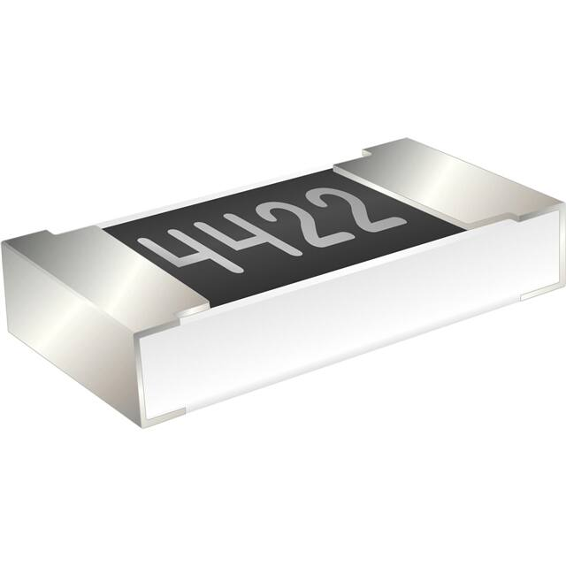


 工商网监
湘ICP备2023018690号
工商网监
湘ICP备2023018690号
