CERAMIC CAPACITORS
Taping
CH
Series
: dimensions
Classic HiQ
According to
ESA Qualified
FEATURES
ELECTRICAL AND ENVIRONMENTAL SPECIFICATIONS
• Low ESR, Ultra High-Q, High Self-Resonant Frequencies
• RF & Microwave capacitors
• Voltage range: 50V - 1,500V
• Capacitance range: 0.1pF - 1,000pF
• Operating temperature up to 125°C*
• Porcelain Capacitors P100
• Laser Marked (optional)
• RoHS compliant
Electrical specifications
Parameter
Capacitance
Value
0.1pF - 1,000pF
A, B, C, D below 10pF
F, G, J, K above 10pF
See capacitance range chart
(100 ± 30) ppm/°C, –55°C to +125°C
106 MΩ min.
2.5 x WVDC for WVDC ≤ 500V
1.8 x WVDC for extended range values ≥ 820pF
1.5 x WVDC for WVDC > 500V
none
none
Tolerances
Working voltage (WVDC)
Temperature coefficient
Insulation Resistance
Dielectric Withstanding
(test voltage applied for 5 seconds)
APPLICATIONS
Aging
Piezo Effect
• Cellular Base Station Amplifiers
• Industrial
• Medical (MRI)
• Scientific
Environmental specifications
Parameter
CIRCUIT APPLICATIONS
Value
2,000 hours, +125°C at 2 x WVDC
(standard WVDC range)
And CHB up to 100pF: 1,000 hours, 175°C at 500V
240 hours, 85% relative humidity at 85°C
(ESA/SCC n°3009)
56 days, 93% relative humidity at 40°C
0V, 5V, WVDC
Life Test
• DC to RF Conversion
• Matching Networks
• Tuning, Coupling and DC Blocking
Moisture Resistance Test 1
Moisture Resistance Test 2
PHYSICAL CHARACTERISTICS
* The temperature range for the CHB up to 100pF is upgrated from +125°C to +175°C.
• Chip capacitors for surface mounting with copper
(non magnetic) or nickel barrier and tinning
• Ribbon leads for surface mounting
HOW TO ORDER
152
CH
B
100
J
S
1
L
E
Voltage code
Dielectric
Size code
Capacitance code
Tolerance code
Termination code
Ribbon code
Marking code
Tape and reel
500 = 50V
101 = 100V
201 = 200V
251 = 250V
301 = 300V
501 = 500V
601 = 600V
102 = 1,000V
152 = 1,500V
CH =
(100±30)
ppm/°C
A = 0505
B = 1111
Please refer to
capacitance code
given in capacitance
range chart
A = ±0.05pF
B = ±0.1pF
C = ±0.25pF
D = ±0.5pF
F = ±1%
G = ±2%
J = ±5%
K = ±10%
See note 1
S = Standard:
tin-plated nickel
-: no lead or ribbon
-: no marking
-: no tape and reel
Available on size
1111:
L = laser marking
E = horizontal orientation
C = Non-magnetic:
tin-plated copper
See note 2
1 = Micro-strip
ribbons
6 = Radial leads
0.1pF (0R1) non
available with
these terminations.
Please refer to voltage given
in capacitance range chart
X = verticale orientation
CHA:
3,000 components per reel
-RoHS
The RoHS tag is
not part of the
reference
Tag added at the
end of P/N for
information
CHB:
1,000 components per reel
See note 3
Note 1: For capacitance values less than 10pF, tolerances B, C and D available. Tolerance code A available for: A case for capacitance values of 0.1pF - 4.7pF. B case for capacitance values of 0.1pF - 3.3pF. For capacitance values of 10pF or higher,
tolerances F, G, J and K available.
Note 2: All terminations are backward compatible and lead-free. The non-magnetic terminations are all Magnetism-free Rated.
Note 3: When coding ribbons for the description of the part, the termination has to be mentioned for MR certified types to ensure that only non-magnetic materials are used.
Note 4: Ribbon lead styles capacitors are not available in Tape and Reel.
Examples: 501 CHB 470 J1L any termination material could be used. 501 CHB 470 JC1L only non-magnetic termination materials could be used.
Please consult us for specific requirements.
www.exxelia.com
152
Page revised 02/21
�CERAMIC CAPACITORS
Taping : dimensions
General
Information
CAPACITOR TERMINATIONS AND SOLDERING
RECOMMENDATIONS
condition. The vapor phase and IR reflow soldering are less aggressive,
inducing more restricted thermal shocks. This is the reason why they are
preferred to the wave soldering method for reliable applications. In all cases,
proper pre-heating is essential.
I. TERMINATION TYPES
The circuit should be pre-heated at a typical rate of 1°C/s within 65°C to 100°C of
the maximum soldering temperature. While multilayer ceramic capacitors can
withstand the peak soldering temperatures for short durations, they should be
minimized whenever possible.
Our capacitors are delivered with one of the following terminations (for
technical reasons, only a limited number of termination types are available in
certain cases). All our terminations are backward compatible.
Parameter
Value
Comment
Termination
Materials
A
C
S
non-magnetic (silver-palladium)
non-magnetic (pure tin over copper barrier)
lead-free (pure tin over nickel barrier)
Above precaution given for SMD types are applicable for the implementation
of large bare chips (1515 and above). But in general, large bare chips above
2225 are not recommended to be mounted on epoxy printed board due to the
thermal expansion mismatch between ceramic capacitor body and epoxy. This
is the reason why leaded components will be preferred especially for reliable
applications.
For information, the typical thermal profiles of these three soldering processes
are given hereafter. These typical diagrams are only given as an aid to SMD
users in determining specific processes linked to their instrumentations and
to their own experience.
NB:
• terminations type C recommended for non magnetic applications.
• termination type A available for non magnetic applications (for historical
reason, we have also another code, the code “P”, for the same type of
termination. The parts that were designed-in before 2005 might still have
a code “P” instead of “A” in the part numbering. But both codes correspond
to the same type of termination).
NB: reference documents are IEC 61760-1, CECC30000 and IEC68 standards.
Please, refer to this standard for more information.
III.1.1. Vapour Phase Soldering
II. SPECIFICATIONS
250°C
Care must be taken when using particular terminations: if the terminations are
heated up above a particular temperature and/or for too long a period of time,
there is a risk of leaching (dissolution of the termination revealing the inner
electrodes).
20s ... 40s
230°C
217°C
200°C
ca. 60s ... 130s
>217°C
150°C
The chart below gives the resistance to soldering heat per termination type,
based on a SAC387 solder bath at 260°C.
Ramp down
rate
很抱歉,暂时无法提供与“501CHB120JSLE”相匹配的价格&库存,您可以联系我们找货
免费人工找货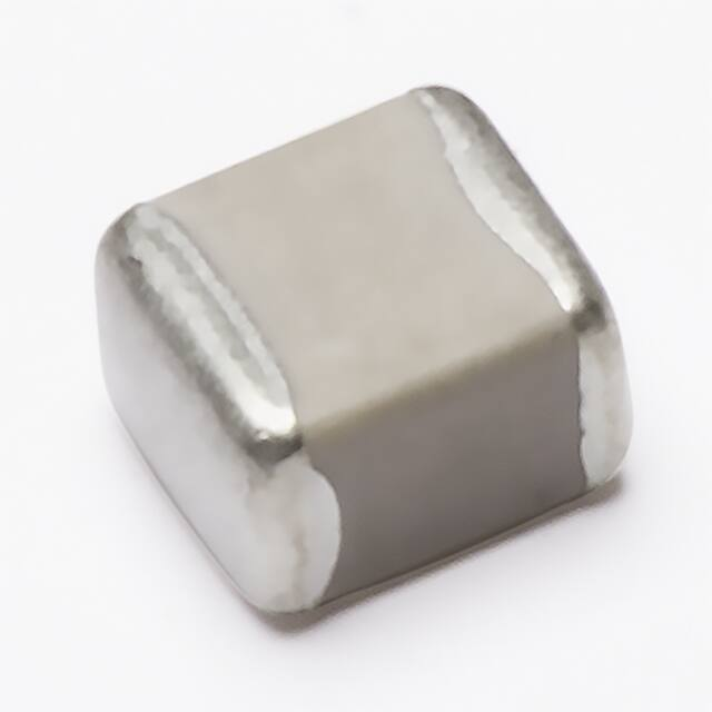


 工商网监
湘ICP备2023018690号
工商网监
湘ICP备2023018690号
