BX-5-IC/V-IC/V-IC/V-IC/V 数据手册
| BEI ELECTRONIC MODULES
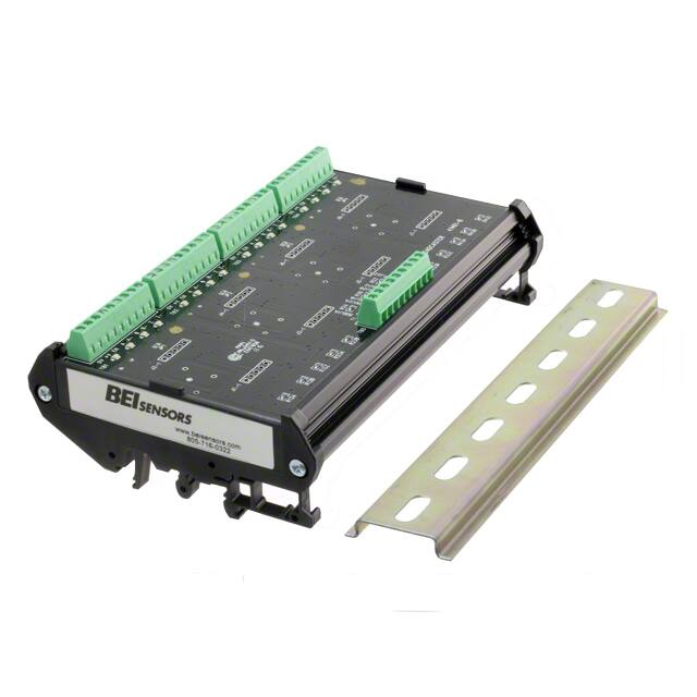
ENCODER SIGNAL BROADCASTER
Introduction
The BROADCASTER accepts standard incremental encoder inputs, (two channels in quadrature plus an index and complements) and can broadcast up to
four encoder signals to four independent devices. Each of the broadcast signals is optically isolated eliminating ground loops. This compact package also
allows for signal processing options, such as anti-dither filter, integer countdown or pulse and direction outputs, to be incorporated into each of the four
broadcast signals independently. The broadcaster is ideal for driving multiple receivers from a single encoder in applications like electronic line shafting or
synchronization of multiple devices to a single operation.
The module accepts signals of 5, 12-15 and 24 VDC and provides three output options: Vout = Vin, Vout = 5 V or NPN open collector. The compact package
mounts to standard EN 50 022 35mm X 7.5mm DIN rail and is 142mm wide, 78mm deep and 45mm above the DIN rail. A 155mm section of DIN rail is
included.
Features
• Broadcasts signals from a single encoder to four independent receivers
• Signal processing modules (pulse converter, integer countdown, antidither) can be added to each output for additional capabilities
• Accepts all standard input voltages and types: single ended, differential
and open collector
• Signals are optically isolated for high noise immunity
• Compact package saves installation costs
SPECIFICATIONS
(For Isolated Circuit And Anti-Dither Functions)
Differential Line Driver (See Figure 1)
The Encoder signals from 5 VDC to 24 VDC
(must specify the voltage when ordering)
This is the preferred type of encoder output
as it has the best noise immunity. Connect
each encoder signal to its like input
(A to A, A/ to A/, etc).
Page 1
Copyright © 2018 Sensata Technologies, Inc.
www.sensata.com
�Single Ended Line Driver (See Figure 2)
Encoder signal from 5 VDC to 24 VDC (must
specify the voltage when ordering)
Connect broadcaster A to optical isolator
module input channel A, B to B and Z to
Z. Connect the A/, B/, and Z/ inputs of the
optical isolator to circuit common of the
encoder supply. Single ended operation is
limited to shorter cable runs and is more
susceptible to noise.
Open Collector with or without Internal
Pull-up Resistors (See Figure 3)
Encoder NPN (sinking) outputs.
Connect encoder output A to optical isolator
module input A/, B to B/ and Z to Z/. Connect
the A, B, and Z inputs of the broadcaster
to the positive encoder supply line. This
connection results in a logic inversion within
the broadcaster module. To compensate for
the logic reversal, swap A for A/, B for B/,
and Z for Z/ at the broadcaster outputs.
TERMINATION PINOUTS
Encoder Side
PIN
Description
Notes
A, A/
Channel A Inputs
B, B/
Channel B Inputs
Z, Z/
Channel Z Inputs
Input levels consistent with specified value in model number
(5 V, 15 V, 24 V).
Signal input current 25 mA nom.
See BEI Optical Isolator Module Applications Guide for single ended
and open collector connection diagrams.
T1, T2, T3
Uncommitted Terminals
Non-committed terminals.
Provided for use as connection points for encoder power.
Page 2
Copyright © 2018 Sensata Technologies, Inc.
www.sensata.com
�Driver Side
PIN
Description
Notes
+V
Power supply 5 – 28 VDC
125 mA + load current typ.
0V
Power supply common
Supply lines between driver sections are not connected. Driver must
be powered in order to produce an output. Supply voltage need not be
the same for different driver sections.
EN
Output Enable
HI = Output Active, LO = High Impedance Internal pull-up to V+
A, A/
Channel A Outputs
B, B/
Channel B Outputs
Z, Z/
Channel Z Outputs
Output levels consistent with driver type and supply voltage (V/V
outputs).
BROADCASTER BLOCK DIAGRAM
Driver #1
Input A
Input AInput B
Input B-
+V (Supply Voltage)
0V (Circuit Ground)
Input A
Input A-
OptoIsolator
#1
Input B
Input B-
Input Z
Input Z-
Input Z
Input ZEN (Enable High)
Driver #4
+V (Supply Voltage)
0V (Circuit Ground)
Input A
Input A-
OptoIsolator
#4
Input B
Input BInput Z
Input ZEN (Enable High)
Page 3
Copyright © 2018 Sensata Technologies, Inc.
www.sensata.com
�Example : BX-5-IC/V-IC/V-P2/5-P2/5
ORDERING OPTIONS
BX
Broadcaster
-
5
-
Output Voltage
from Encoder:
5, 15, 24
IC/V
-
Function for
Channel 1
IC/V
-
Function for
Channel 2
Choose one for each channel:
DB = Divide By, selectable integer value 1-256
AD= Anti-Dither
Px = Pulse Up/Down where x = multiple, either 1, 2, or 4
PxD = Pulse Direction where x = multiple, either 1, 2, or 4
IC = Isolation Circuit (Standard)
P2/5
-
Function for
Channel 3
P2/5
Function for
Channel 4
Output Voltage/Type:
/V = Multivoltage 5-28 Volts in, Vout = Vin
/5 = Multivoltage 5-28 Volts in, Vout = 5V regulated
/OC = Multivoltage 5-28 Volts in, Vout = Open Collector
ADDITIONAL MODULES AND ACCESSORIES
Power Supply
With a wide range of acceptable input voltages (AC and DC) this DIN Rail mountable power
supply is usable in virtually all industrial applications worldwide. It has built in surge protection
to reduce faults due to transients and it has 100% reserve capacity for startup and overload
conditions.
Cable And Cable Assemblies
Cable reels for your own custom wiring requirements or cable assemblies are available, using
high quality custom BEI standard cable consisting of four, low capacitance shielded twisted
pairs with an overall shield, extra large conductors for power, and signal ground; all within an
abrasion-resistant PVC jacket.
Cable Reels
100 ft. reel
500 ft. reel
Cable Assemblies
Part Nos. for MS3106F14S-6S Mating Connector
10 ft. # 31186-1410 | 20 ft. # 31186-1420 | 30ft. # 31186-1430
Part Nos. for MS3106F16S-1S Mating Connector
10 ft. # 31186-1610 | 20 ft. # 31186-1620 | 30ft. # 31186-1630
Part Nos. for MS3106F18S-1S Mating Connector
10 ft. # 31186-1810 | 20 ft. # 31186-1820 | 30ft. # 31186-1830
Part No. 37048-003-100
Part No. 37048-003-500
Page 4
Copyright © 2018 Sensata Technologies, Inc.
www.sensata.com
�WARNINGS
HAZARD OF ELECTRIC SHOCK, EXPLOSION OR ARC FLASH
• Disconnect all power before installing or working with this equipment
• Verify all connections and replace all covers before turning on power
Failure to follow these instructions will result in death or serious injury.
Page 5
Sensata Technologies, Inc. (“Sensata”) data sheets are solely intended to assist designers (“Buyers”) who are developing systems that
incorporate Sensata products (also referred to herein as “components”). Buyer understands and agrees that Buyer remains responsible
for using its independent analysis, evaluation and judgment in designing Buyer’s systems and products. Sensata data sheets have
been created using standard laboratory conditions and engineering practices. Sensata has not conducted any testing other than that
specifically described in the published documentation for a particular data sheet. Sensata may make corrections, enhancements,
improvements and other changes to its data sheets or components without notice.
Buyers are authorized to use Sensata data sheets with the Sensata component(s) identified in each particular data sheet. HOWEVER, NO
OTHER LICENSE, EXPRESS OR IMPLIED, BY ESTOPPEL OR OTHERWISE TO ANY OTHER SENSATA INTELLECTUAL PROPERTY RIGHT, AND
NO LICENSE TO ANY THIRD PARTY TECHNOLOGY OR INTELLECTUAL PROPERTY RIGHT, IS GRANTED HEREIN. SENSATA DATA SHEETS
ARE PROVIDED “AS IS”. SENSATA MAKES NO WARRANTIES OR REPRESENTATIONS WITH REGARD TO THE DATA SHEETS OR USE
OF THE DATA SHEETS, EXPRESS, IMPLIED OR STATUTORY, INCLUDING ACCURACY OR COMPLETENESS. SENSATA DISCLAIMS
ANY WARRANTY OF TITLE AND ANY IMPLIED WARRANTIES OF MERCHANTABILITY, FITNESS FOR A PARTICULAR PURPOSE, QUIET
ENJOYMENT, QUIET POSSESSION, AND NON-INFRINGEMENT OF ANY THIRD PARTY INTELLECTUAL PROPERTY RIGHTS WITH REGARD
TO SENSATA DATA SHEETS OR USE THEREOF.
All products are sold subject to Sensata’s terms and conditions of sale supplied at www.sensata.com SENSATA ASSUMES NO LIABILITY
FOR APPLICATIONS ASSISTANCE OR THE DESIGN OF BUYERS’ PRODUCTS. BUYER ACKNOWLEDGES AND AGREES THAT IT IS SOLELY
RESPONSIBLE FOR COMPLIANCE WITH ALL LEGAL, REGULATORY AND SAFETY-RELATED REQUIREMENTS CONCERNING ITS PRODUCTS,
AND ANY USE OF SENSATA COMPONENTS IN ITS APPLICATIONS, NOTWITHSTANDING ANY APPLICATIONS-RELATED INFORMATION
OR SUPPORT THAT MAY BE PROVIDED BY SENSATA.
Mailing Address: Sensata Technologies, Inc., 529 Pleasant Street, Attleboro, MA 02703, USA.
Copyright © 2018 Sensata Technologies, Inc.
Rev:12/04/18
CONTACT US
Americas
+1 (800) 350 2727 – Option 1
sales.beisensors@sensata.com
Europe, Middle East & Africa
+33 (3) 88 20 8080
position-info.eu@sensata.com
Asia Pacific
sales.isasia@list.sensata.com
China +86 (21) 2306 1500
Japan +81 (45) 277 7117
Korea +82 (31) 601 2004
India +91 (80) 67920890
Rest of Asia +886 (2) 27602006
ext 2808
www.sensata.com
�


 工商网监
湘ICP备2023018690号
工商网监
湘ICP备2023018690号
