SCC1-RS485-PIGTAIL 2M 数据手册
Sensirion RS485 and USB Sensor Cable
SCC1-RS485 and SCC1-USB
▪ Robust RS485 Interface for bus and long
distance communication in demanding
environments
▪ Easy to use USB Interface for laboratory and
desktop use
▪ Applicable to digital SLQ, SLI, SLS and SLG
liquid flow sensors
Product Summary
The SCC1-RS485 sensor cable for Sensirion’s flow meters allows the installation and use of I²C based sensors
in a demanding industrial automation environment. In addition to the standard commands available for the I²C
interface of the sensor, the incorporated microcontroller of the cable provides more complex logic such as a
dispense volume totalizer, automatic dispense detection, automatic heater control and data buffer for asynchronous read-out.
The SCC1-USB sensor cable provides the same functionality as the SCC1-RS485 with a plug and play USB
interface. Together with the free Sensor Viewer software, this is the perfect combination to start testing a
Sensirion liquid flow meter.
Sensirion provides detailed protocol specifications, implementation documentation and a driver DLL with
convenient access functions for use under Microsoft Windows®.
www.sensirion.com
Version 5 – June 2018
1/9
�Content
1 Pigtail RS485 and USB Versions
3
2 Available Driver DLL and Protocol Documentation
3
3 Specifications for the SCC1-RS485 Sensor Cable with Pigtail End
4
4 Specifications for the SCC1-USB Sensor Cable with Integrated USB Plug
6
5 General Specifications
6
6 Ordering Information
7
7 Important Notices
8
8 Revision History
9
9 Headquarters and Subsidiaries
9
www.sensirion.com
Version 5 – June 2018
2/9
�1 Pigtail RS485 and USB Versions
The digital SCC1 sensor cable is available in a pigtail variant and in a version with integrated USB plug. The pigtail cable
provides an RS485 interface and needs to be powered by 5 V. The USB cable converts the RS485 to the USB interface
and is directly powered by the USB port of the host PC.
Both variants can be connected to the 4-pin M8 connector of Sensirion’s liquid flow meters. The interface electronics are
molded into the cable. The SCC1-USB has a total length of about 2 m, the SCC1-RS485 is available with a total length
of 2 m or 5 m.
USB
I2C
I2C
RS485
RS485
RS485
Figure 1: SCC1 cable connected to a sensor with pigtail cable (left) and with USB plug (right). Communication interfaces shown in small print.
2 Available Driver DLL and Protocol Documentation
For use under Microsoft Windows®, Sensirion supplies a driver DLL that offers simple C type functions for direct access
from any programming language capable of opening DLLs.
Documentation and sample code for the DLL as well as documentation and implementation instructions for the
communication protocol are available on request.
www.sensirion.com
Version 5 – June 2018
3/9
�3 Specifications for the SCC1-RS485 Sensor Cable with Pigtail End
3.1 RS485 Commands in SHDLC
For using the cable and sensor with a microcontroller, the Sensirion-HDLC (high-level data link control) protocol is used.
See separate documentation for the SHDLC command set, guidelines on how to implement the protocol and example
code.
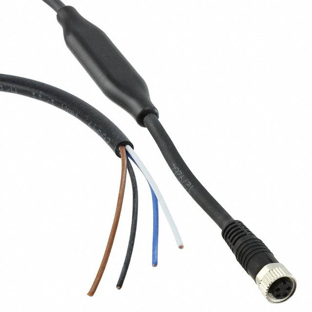
3.2 Pigtail Wire Assignment
One side of the SCC1-RS485 cable is connected to the 4-pin M8 connector of Sensirion’s liquid flow meters. The other
side has four wires: Two for power supply and ground and two for half-duplex RS485 communication.
The wire assignment is defined in Table 1.
WARNING!
Incorrect connection may lead to permanent damage of the cable. Check the wire assignment carefully.
Wire
Blue
White
Brown
Black
Function
Supply voltage (5 V)
Ground
RS485 D+
RS485 D-
Symbol
VDD
GND
D+
D-
PC
- or Microcontroller
Power Supply
D+
DGND
Brown – D+
Black – DWhite – GND
Blue – VDD
Sensor Cable
GND
+5V
Table 1 and Figure 2: Wire assignment and wiring diagram
3.3 Electrical Specifications SCC1-RS485
Parameter
Min
Typical
Max
Unit
Supply Voltage1
3.5
5
7
V
+/- 0.3
V
< 10
kHz
20
25
mA
20
100
mA
Voltage Stability
Current Consumption
Sensor measuring, without RS485 communication2
Current Consumption
Sensor measuring, during RS485 communication2
Table 2: Electrical Specifications
3.4 Ground Connection
It is necessary to connect the ground of the sensor cable to the ground of the power supply and to the ground of your
system’s RS485 interface. The sensor cable is not equipped with an optocoupler or other electrical isolation between the
power supply and the communication lines.
3.5 Baud Rate and RS485 Address
Available baud rates are: 1200, 2400, 4800, 9600, 14400, 19200, 38400, 57600, 115200, 230400 baud, with a default
of 115200.
The default RS485 address of the SCC1-RS485 cable is 0.
1
2
The minimum supply voltage depends on the sensor the cable is used with.
Including 6 mA for the sensor, see the datasheet of the used sensor for details.
www.sensirion.com
Version 5 – June 2018
4/9
�A configuration software for Windows PC to change the baud rate and/or RS485 address is available on the Sensirion
website: www.sensirion.com/de/download-center/.
3.6 Maximal Number of Devices
The theoretical maximum of SCC1-RS485 sensor cables that can be connected on one RS485 bus is 255. However, a
large number of devices on the same bus requires a well-designed network layout. Depending on the chosen sampling
rate and amount of data per reading of the sensor (e.g. 1kHz vs 100 Hz; one signal vs. 3 signals), the bus bandwidth
may limit the number of devices to about 3-5 devices (at 1 kHz) or 30 or more devices (100 Hz or lower) for a bus with
115’200 kbit/s.
3.7 Network Topology
The network has to be designed to suit the application’s requirements. The recommended network topology for the
RS485 network is a linear, multi-drop configuration with short (1-2 m) branch lines to the sensors.
Figure 3: Linear, multi-drop topology with short branch lines
3.8 Termination Resistor
Termination in RS485 networks is used to avoid signal reflections that cause communication errors. Short networks with
few cables may also work without termination but with increasing length and number of sensors the termination of the
last sensor of the chain should be turned on. In this case it is also recommended to terminate and bias the master with
the following resistor network.
720 Ω
RS485 D+
Master D+
130 Ω
RS485 D-
Master D720 Ω
Figure 4: Typical bias network that should be used on the master side
It is also possible to terminate the network manually with a 120 Ohm resistor.
When using the SCC1-USB cable, the termination should not be turned on because it is not possible to terminate the
master side.
www.sensirion.com
Version 5 – June 2018
5/9
�4 Specifications for the SCC1-USB Sensor Cable with Integrated USB Plug
4.1 PC Driver
When plugging in the SCC1-USB cable, the necessary Virtual Com-Port (VCP) driver should install itself automatically.
After the driver has been successfully installed, the device appears in the device manager as “USB Serial Port”. If this
does not happen, please install the VCP driver manually from this place:
http://www.ftdichip.com/Drivers/VCP.htm.
4.2 COM Port and Baud Rate
The host computer will assign a COM port address to the SCC1-USB cable. The standard baud rate is 115’200, Echo is
Off, RS485 address is 0.
If more than one SCC1-USB cables are connected to the same computer, each USB cable will have its own COM port
but all cables will have the same RS485 address (0).
A configuration software for Windows PC to change the baud rate and/or RS485 address is available on Sensirion’s
website: https://www.sensirion.com/de/download-center/.
4.3 Electrical Specifications SCC1-USB
Parameter
Min
Typical
Max
Unit
Supply Voltage3
4.75
5
5.25
V
+/- 0.3
V
< 10
kHz
25
mA
Voltage Stability
Current Consumption
20
Table 3: Electrical Specifications
5 General Specifications
5.1 Dimensions
Approximate mechanical dimensions of the electronics overmold are shown in Figure 5, dimensions and specifications
of the cable are listed in Section 3.
Figure 5: Mechanical dimensions of electronics overmold
3
The minimum supply voltage depends on the sensor the cable is used with.
www.sensirion.com
Version 5 – June 2018
6/9
�Parameter
Length of cable on sensor side (including M8 connector)
Length of cable on pigtail end
Cable outer jacket diameter on pigtail end
Conductor cross section
Outer diameter of individual wires
Minimum bending radius5
Value
~10 cm
~190 cm / ~490 cm4
4.4 ± 0.2 mm
0.25 mm2 (24 AWG)
1.15 ± 0.05 mm
10x cable diameter
Table 4: Mechanical specifications
5.2 Materials
Part
Cable jacket
Wire insulation
Connector housing
Connector screw ring
Electronics overmold
Material
PUR
PP
PUR
Zn Al/Ni
Polyamide hotmelt
Table 5: List of materials
5.3 Placing of Incorporated Electronics
The electronics of the sensor cable are housed in the molded bulge of the cable. Because of the power consumption of
the electronics, the cable can heat up minimally at the bulge when in use. To avoid disturbing the flow sensor’s
measurement it we do not advised to attach the bulge to the flow sensor housing.
5.4 Bending and Forces on Cable
Excessive, repetitive bending of the cable at the connections to the molded bulge may lead to cable breakage. Fasten
the cable/bulge properly.
5.5 Device Certification
The SCC1 sensor cable is RoHS and REACH compliant. The combination of the RS485 or USB cable with flow meters
of the digital SLI-, SLQ-, SLS-, and SLG-series is CE certified; see datasheet of specific flow meter.
6 Ordering Information
Please use the following product names and article numbers when ordering the SCC1 sensor cable.
Product Name
Product
Article No
SCC1-RS485 2m
SCC1-RS485 Sensor Cable (pigtail end), 2 m length
1-100804-01
SCC1-RS485 5m
SCC1-RS485 Sensor Cable (pigtail end), 5 m length
1-101122-01
SCC1-USB
SCC1-USB Sensor Cable, 2m length
1-101007-01
Table 6: Ordering Information
4
5
For SCC1-USB 2m and SCC1-RS485 2m / SCC1-RS485 5m
Bending radius of the cable. Avoid excessive and repetitive bending at the transition of the cable to the overmold.
www.sensirion.com
Version 5 – June 2018
7/9
�7 Important Notices
7.1 Warning, Personal Injury
Do not use this product as safety or emergency stop devices or in any other application where failure of the product could result in
personal injury. Do not use this product for applications other than its intended and authorized use. Before installing, handling, using or
servicing this product, please consult the data sheet and application notes. Failure to comply with these instructions could result in
death or serious injury.
If the Buyer shall purchase or use SENSIRION products for any unintended or unauthorized application, Buyer shall defend, indemnify and hold
harmless SENSIRION and its officers, employees, subsidiaries, affiliates and distributors against all claims, costs, damages and expenses, and
reasonable attorney fees arising out of, directly or indirectly, any claim of personal injury or death associated with such unintended or unauthorized
use, even if SENSIRION shall be allegedly negligent with respect to the design or the manufacture of the product.
7.2 ESD Precautions
The inherent design of this component causes it to be sensitive to electrostatic discharge (ESD). To prevent ESD-induced damage and/or
degradation, take customary and statutory ESD precautions when handling this product.
7.3 Warranty
SENSIRION warrants solely to the original purchaser of this product for a period of 12 months (one year) from the date of delivery that this product
shall be of the quality, material and workmanship defined in SENSIRION’s published specifications of the product. Within such period, if proven to
be defective, SENSIRION shall repair and/or replace this product, in SENSIRION’s discretion, free of charge to the Buyer, provided that:
▪ notice in writing describing the defects shall be given to SENSIRION within fourteen (14) days after their appearance;
▪ such defects shall be found, to SENSIRION’s reasonable satisfaction, to have arisen from SENSIRION’s faulty design, material, or workmanship;
▪ the defective product shall be returned to SENSIRION’s factory at the Buyer’s expense; and
▪ the warranty period for any repaired or replaced product shall be limited to the unexpired portion of the original period.
This warranty does not apply to any equipment which has not been installed and used within the specifications recommended by SENSIRION for
the intended and proper use of the equipment. EXCEPT FOR THE WARRANTIES EXPRESSLY SET FORTH HEREIN, SENSIRION MAKES NO
WARRANTIES, EITHER EXPRESS OR IMPLIED, WITH RESPECT TO THE PRODUCT. ANY AND ALL WARRANTIES, INCLUDING WITHOUT
LIMITATION, WARRANTIES OF MERCHANTABILITY OR FITNESS FOR A PARTICULAR PURPOSE, ARE EXPRESSLY EXCLUDED AND
DECLINED.
SENSIRION is only liable for defects of this product arising under the conditions of operation provided for in the data sheet and proper use of the
goods. SENSIRION explicitly disclaims all warranties, express or implied, for any period during which the goods are operated or stored not in
accordance with the technical specifications.
SENSIRION does not assume any liability arising out of any application or use of any product or circuit and specifically disclaims any and all liability,
including without limitation consequential or incidental damages. All operating parameters, including without limitation recommended parameters,
must be validated for each customer’s applications by customer’s technical experts. Recommended parameters can and do vary in different
applications.
SENSIRION reserves the right, without further notice, (i) to change the product specifications and/or the information in this document and (ii) to
improve reliability, functions and design of this product.
Copyright© 2018, by SENSIRION.
CMOSens® is a trademark of Sensirion
All rights reserved
www.sensirion.com
Version 5 – June 2018
8/9
�8 Revision History
Date
December 2012
September 2013
October 2013
July 2014
May 2018
Version
1
2
3
4
5
Page(s)
all
2
4
all
all
Changes
First official release
Baud rate and RS485 address. USB Variant
CE, RoHS etc. Statement: typo with QT500 corrected
Term ‘Controller’ removed from cable naming, 5m variant added
New Format, updates on dimensions, materials, termination, and bias network
9 Headquarters and Subsidiaries
Sensirion AG
Laubisruetistr. 50
CH-8712 Staefa ZH
Switzerland
Sensirion Inc., USA
phone: +1 312 690 5858
info-us@sensirion.com
www.sensirion.com
Sensirion Korea Co. Ltd.
phone: +82 31 337 7700~3
info-kr@sensirion.com
www.sensirion.co.kr
phone: +41 44 306 40 00
fax:
+41 44 306 40 30
info@sensirion.com
www.sensirion.com
Sensirion Japan Co. Ltd.
phone: +81 3 3444 4940
info-jp@sensirion.com
www.sensirion.co.jp
Sensirion China Co. Ltd.
phone: +86 755 8252 1501
info-cn@sensirion.com
www.sensirion.com.cn
Sensirion Taiwan Co. Ltd
phone: +886 3 5506701
info@sensirion.com
www.sensirion.com
To find your local representative, please visit www.sensirion.com/distributors
www.sensirion.com
Version 5 – June 2018
9/9
�


 工商网监
湘ICP备2023018690号
工商网监
湘ICP备2023018690号
