IS31LT3954A
CONSTANT-CURRENT 3-AMPERE PWM DIMMABLE BUCK
REGULATOR LED DRIVER WITH OUTPUT FAULT REPORTING
September 2021
GENERAL DESCRIPTION
FEATURES
The IS31LT3954A is a DC-to-DC switching converter
that integrates an N-channel MOSFET to operate in a
buck configuration. The device can operate from a
wide input voltage between 4.5V and 38V and
provides a constant current of up to 3A for driving a
single LED or multiple series connected LEDs.
The external resistor, RISET, is used to set a constant
LED output current, while allowing the output voltage
to be automatically adjusted for a variety of LED
configurations.
The IS31LT3954A operates in a fixed frequency mode
during switching. There is an external resistor
connected between the VCC and TON pins used to
configure the on-time (switching frequency). The
switching frequency is dithered for spread spectrum
operation which will spread the electromagnetic
energy into a wider frequency band. This function is
helpful for optimizing EMI performance.
A logic input PWM signal applied to the enable (EN)
pin will adjust the average LED current. The LED
brightness is proportional to the duty cycle of the
PWM signal.
True average output current operation is achieved
with fast transient response by using cycle-by-cycle,
controlled on-time method.
In addition, IS31LT3954A integrates various fault
protections for robust operation. Detection of these
faults is reported by the FAULTB I/O pin. Multiple
devices can have their FAULTB pins connected to
create a “One-Fail-All-Fail” system operation.
Wide input voltage supply from 4.5V to 38V
- Withstand 40V load dump
True average output current control
3A maximum output over operating temperature
range
Cycle-by-cycle current limit
Integrated high-side MOSFET switch
Dimming via direct logic input or power supply
voltage
Internal control loop compensation
Under-voltage lockout (UVLO) and thermal
shutdown protection
2μA low power shutdown
Spread spectrum to optimize EMI
Robust fault protection and reporting function:
- Pin-to-GND short
- Component open/short faults
- Adjacent pin-to-pin short
- LED open/short
- Thermal shutdown
Shared fault flag for multiple device operation to
meet “One-Fail-All-Fail”
APPLICATIONS
General high brightness LED lighting
Architecture lighting
Dimmable lights
Pool lighting
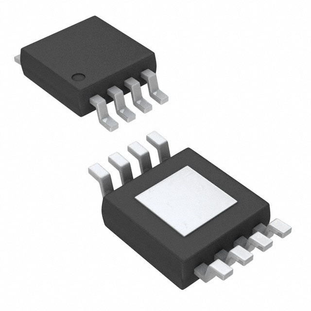
The IS31LT3954A is available in an SOP-8-EP
package with an exposed pad for enhanced thermal
dissipation. It operates from 4.5V to 38V over the
temperature range of -40°C to +125°C.
Lumissil Microsystems – www.lumissil.com
Rev. D, 09/01/2021
1
�IS31LT3954A
TYPICAL APPLICATION CIRCUIT
Figure 1
Figure 2
Typical Application Circuit
Typical Application Circuit (Several Devices In Parallel with FAULTB Interconnection)
Lumissil Microsystems – www.lumissil.com
Rev. D, 09/01/2021
2
�IS31LT3954A
PIN CONFIGURATION
Package
Pin Configuration (Top View)
SOP-8-EP
PIN DESCRIPTION
No.
Pin
Description
1
VCC
Power supply input. Connect a bypass capacitor CIN to ground.
The path from CIN to GND and VCC pins should be as short as
possible.
2
TON
On-time setting. Connect a resister from this pin to VCC pin to
set the regulator controlled on-time.
3
EN/PWM
Logic input for enable and PWM dimming. Pull up above 1.4V to
enable and below 0.4V to disable. Input a 100Hz~20kHz PWM
signal to dim the LED brightness.
4
FB
Drive output current sense feedback. Set the output current by
connecting a resister from this pin to the ground.
5
FAULTB
Open drain I/O diagnostic pin. Active low output driven by the
device when it detects a fault condition. As an input, this pin will
accept an externally generated FAULTB signal to disable the
device output to satisfy the “One-Fail-All-Fail” function. Note this
pin requires an external pull up resistor (RPU).
6
GND
Ground.
7
BOOT
Internal MOSFET gate driver bootstrap. Connect a 0.1µF X7R
ceramic capacitor from this pin to LX pin.
8
LX
Internal high-side MOSFET switch output. Connect this pin to
the inductor and Schottky diode.
Thermal Pad
Connect to GND.
Lumissil Microsystems – www.lumissil.com
Rev. D, 09/01/2021
3
�IS31LT3954A
ORDERING INFORMATION
Industrial Range: -40°C to +125°C
Order Part No.
Package
QTY/Reel
IS31LT3954A-GRLS4-TR
SOP-8-EP, Lead-free
2500
Copyright © 2021 Lumissil Microsystems. All rights reserved. Lumissil Microsystems reserves the right to make changes to this specification and its
products at any time without notice. Lumissil Microsystems assumes no liability arising out of the application or use of any information, products or
services described herein. Customers are advised to obtain the latest version of this device specification before relying on any published information and
before placing orders for products.
Lumissil Microsystems does not recommend the use of any of its products in life support applications where the failure or malfunction of the product can
reasonably be expected to cause failure of the life support system or to significantly affect its safety or effectiveness. Products are not authorized for use in
such applications unless Lumissil Microsystems receives written assurance to its satisfaction, that:
a.) the risk of injury or damage has been minimized;
b.) the user assume all such risks; and
c.) potential liability of Lumissil Microsystems is adequately protected under the circumstances
Lumissil Microsystems – www.lumissil.com
Rev. D, 09/01/2021
4
�IS31LT3954A
ABSOLUTE MAXIMUM RATINGS (NOTE 1)
Input voltage, VCC (Note 2)
Bootstrap to switching voltage, (VBOOT-VLX)
Switching voltage, VLX (Steady state)
Switching voltage, VLX (Transient< 10ns)
EN/PWM, TON and FAULTB voltage, VEN/PWM, VTON and VFAULTB
Current sense voltage, VFB
Power dissipation, PD(MAX)
Operating temperature, TA=TJ
Storage temperature, TSTG
Junction temperature, TJMAX
Package thermal resistance, junction to ambient (4 layer standard
test PCB based on JESD 51-2A), θJA
Package thermal resistance, junction to thermal PAD (4 layer
standard test PCB based on JESD 51-8), θJP
ESD (HBM)
ESD (CDM)
-0.3V ~ +42V
-0.3V ~ +6.0V
-0.6V ~ VCC +0.3V
-3.0V
-0.3V ~ VCC +0.3
-0.3V ~ 6.0V
2.29W
-40°C ~ +125°C
-65°C ~ +150°C
+150°C
43.7 °C/W
1.41 °C/W
±2kV
±750V
Note 1: Stresses beyond those listed under “Absolute Maximum Ratings” may cause permanent damage to the device. These are stress
ratings only and functional operation of the device at these or any other condition beyond those indicated in the operational sections of the
specifications is not implied. Exposure to absolute maximum rating conditions for extended periods may affect device reliability.
Note 2: A maximum of 44V can be sustained at this pin for a duration of ≤ 2s.
ELECTRICAL CHARACTERISTICS
VCC= 24V, TJ=TA= 25°C, unless otherwise noted. (Note 3)
Symbol
VCC
VUVLO
Parameter
Conditions
Input supply voltage
VCC undervoltage lockout threshold
VUVLO_HY VCC undervoltage lockout hysteresis
Min.
Typ.
4.5
VCC increasing
4.05
4.25
VCC decreasing
250
Max.
Unit
38
V
4.45
V
mV
ICC
VCC pin supply current
VFB = 0.5V, VEN/PWM = high
1.2
2
mA
ISD
VCC pin shutdown current
EN/PWM shorted to GND
2
10
µA
4.5
5.5
A
ISWLIM
tOCP
Buck switch current limit threshold
3.5
Over Current Protection (OCP) hiccup
(Note 4)
time
1
ms
RDS_ON
Buck switch on-resistance
VBOOT= VCC+4.3V, ILX= 1A
0.2
VBTUV
BOOT undervoltage lockout threshold
VBOOT to VLX increasing
3.3
V
VBTUV_HY BOOT undervoltage lockout hysteresis
VBOOT to VLX decreasing
400
mV
tOFF_MIN
Switching minimum off-time
VFB = 0V
110
150
ns
tON_MIN
Switching minimum on-time
120
150
ns
tON
Selected on-time
0.4
Ω
VCC= 24V, VOUT= 12V,
RTON= 420kΩ
800
1000
1200
ns
VFB decreasing, LX turns on
195
200
205
mV
Regulation Comparator and Error Amplifier
VFB
Load current sense regulation
threshold
Lumissil Microsystems – www.lumissil.com
Rev. D, 09/01/2021
5
�IS31LT3954A
ELECTRICAL CHARACTERISTICS (CONTINUE)
VCC= 24V, TA=TJ = 25°C, unless otherwise noted. (Note 3)
Symbol
Parameter
Conditions
Min.
Typ.
Max.
Unit
0.1
0.2
V
1
µA
FAULTB OPEN DRAIN OUTPUT
VFAULTB
FAULTB pin pull down voltage
ILK_FAULTB FAULTB pin leakage current
Fault condition, sink current
IOL = 5mA
No fault condition, pull up to
12V
tDELAY1
Fault detect to fault report delay time
10
ms
tDELAY2
Fault recover to fault report delay time
10
ms
VFAULTB_IH
FAULTB pin input high enable
threshold
VFAULTB_IL
FAULTB pin input low disable
threshold
1.4
V
0.4
V
0.4
V
Enable Input
VIH
Logic high voltage
VEN/PWM increasing
VIL
Logic low voltage
VEN/PWM decreasing
RPWMPD
EN/PWM pin pull-down resistance
VEN/PWM= 5V
tPWML
Duration EN/PWM pin kept low to
shutdown the device
tPWMH
tPWMSW
1.4
V
100
200
300
kΩ
55
65
80
ms
Duration EN/PWM pin kept high to quit
(Note 4)
from shutdown mode
16
25
µs
The latency of EN/PWM pull high to IC
(Note 4)
starts switching
120
150
µs
Thermal Shutdown
TSD
Thermal shutdown threshold
(Note 4)
165
°C
TSDHYS
Thermal shutdown hysteresis
(Note 4)
25
°C
Note 3: Production testing of the device is performed at 25°C. Functional operation of the device specified over -40°C to +125°C temperature
range, is guaranteed by design, characterization and process control.
Note 4: Guaranteed by design.
Lumissil Microsystems – www.lumissil.com
Rev. D, 09/01/2021
6
�IS31LT3954A
TYPICAL PERFORMANCE CHARACTERISTICS
2
2
1.8
Supply Current (mA)
Supply Current (mA)
RTON = 200kΩ
TJ = 25°C
EN/PWM = High
1.5
1
1.6
VCC = 12V
RTON = 200kΩ
EN/PWM = High
1.4
1.2
1
0.8
0.6
0.5
0.4
0.2
0
0
10
20
30
0
-40
40
-25
-10
5
Figure 4
ICC vs. VCC
3
50
65
80
95
110
125
80
95
110
125
80
95
110
125
ICC vs. Temperature
2
RTON = 200kΩ
TJ = 25°C
EN/PWM = Low
2.5
1.8
Shutdown Current (µA)
Shutdown Current (µA)
35
Temperature (°C)
Supply Voltage (V)
Figure 3
20
2
1.5
1
1.6
VCC = 12V
RTON = 200kΩ
EN/PWM = Low
1.4
1.2
1
0.8
0.6
0.4
0.5
0.2
0
0
10
20
30
0
-40
40
-25
-10
5
35
50
65
Temperature (°C)
Supply Voltage (V)
Figure 5
20
Figure 6
ISD vs. VCC
ISD vs. Temperature
0.4
0.3
TJ = 25°C
VCC = 12V
0.35
0.25
0.3
RDS_ON (Ω)
RDS_ON (Ω)
0.2
0.15
0.25
0.2
0.15
0.1
0.1
0.05
0
0.05
0
10
20
30
40
0
-40
-25
-10
RDS_ON vs. VCC
Lumissil Microsystems – www.lumissil.com
Rev. D, 09/01/2021
20
35
50
65
Temperature (°C)
Supply Voltage (V)
Figure 7
5
Figure 8
RDS_ON vs. Temperature
7
�IS31LT3954A
100
1600
3LED
95
1560
1540
1520
1500
1480
1460
RISET = 0.13Ω
RTON = 200kΩ
L1 = 10µH
TJ = 25°C
1LED ~ 10LED
1440
1420
1400
4LED 5LED 6LED 7LED 8LED 9LED 10LED
2LED
90
Efficiency (%)
Output Current (mA)
1580
5
10
1LED
85
80
75
70
RISET = 0.13Ω
RTON = 200kΩ
L1 = 10µH
TJ = 25°C
65
15
20
25
30
35
60
40
5
10
15
IOUT vs. VCC
Figure 10
3200
95
3000
2950
2900
RISET = 0.067Ω
RTON = 200kΩ
L1 = 10µH
TJ = 25°C
1LED ~ 9LED
2800
2750
5
10
25
30
35
9LED
RISET = 0.067Ω
RTON = 200kΩ
L1 = 10µH
TJ = 25°C
5
10
15
Supply Voltage (V)
Figure 11
7LED 8LED
75
60
40
5LED 6LED
80
65
20
40
85 1LED
70
15
35
2LED
90
3050
Efficiency (%)
Output Current (mA)
3LED 4LED
3100
2850
30
Efficiency vs. VCC
100
3150
2700
25
Supply Voltage (V)
Supply Voltage (V)
Figure 9
20
20
25
30
35
40
Supply Voltage (V)
IOUT vs. VCC
Figure 12
4.5
Efficiency vs. VCC
220
4.4
VCC = 12V
UVLO_H
4.3
210
UVLO_L
4.1
VFB (mV)
VUVLO (V)
4.2
4
3.9
200
3.8
190
3.7
3.6
3.5
-40
-25
-10
5
20
35
50
65
80
95
110
125
180
-40
10
Temperature (°C)
Figure 13
VUVLO vs. Temperature
Lumissil Microsystems – www.lumissil.com
Rev. D, 09/01/2021
60
110
160
Temperature (°C)
Figure 14
VFB vs. Temperature
8
�IS31LT3954A
3500
2500
Output Current (mA)
Output Current (mA)
3000
3000
VCC = 12V
RISET = 0.067Ω
TJ = -40°C
PWM = 500Hz, 1kHz, 5kHz, 10kHz
2500
2000
1500
1000
2000
1500
1000
500
500
0
0
VCC = 12V
RISET = 0.067Ω
TJ = 25°C
PWM = 500Hz, 1kHz, 5kHz, 10kHz
10
20
30
40
50
60
70
80
90
100
0
0
10
20
30
Duty Cycle (%)
Figure 15
Output Current (mA)
50
60
70
80
90
100
Duty Cycle (%)
IOUT vs. Duty Cycle
Figure 16
3000
2500
40
IOUT vs. Duty Cycle
VCC = 12V
RTON = 200kΩ
TJ = -40°C
VCC = 12V
RISET = 0.067Ω
TJ = 125°C
PWM = 500Hz, 1kHz, 5kHz, 10kHz
2000
VCC
10V/Div
1500
1000
VEN/PWM
10V/Div
500
0
0
10
20
30
40
50
60
70
80
90
100
IL1
1A/Div
Duty Cycle (%)
Figure 17
Time (100µs/Div)
IOUT vs. Duty Cycle
Figure 18
VCC = 12V
RTON = 200kΩ
TJ = 25°C
VCC = 12V
RTON = 200kΩ
TJ = 125°C
VCC
10V/Div
VCC
10V/Div
VEN/PWM
10V/Div
VEN/PWM
10V/Div
IL1
1A/Div
IL1
1A/Div
Time (100µs/Div)
Figure 19
EN/PWM Enable Time
Time (100µs/Div)
EN/PWM Enable Time
Lumissil Microsystems – www.lumissil.com
Rev. D, 09/01/2021
Figure 20
EN/PWM Enable Time
9
�IS31LT3954A
VCC = 12V
PWM = 5V, 1kHz
RTON = 200kΩ
TJ = -40°C
VCC = 12V
PWM = 5V, 1kHz
RTON = 200kΩ
TJ = -40°C
VCC
10V/Div
VCC
10V/Div
VEN/PWM
5V/Div
VEN/PWM
5V/Div
IL1
500mA/Div
IL1
500mA/Div
Time (4µs/Div)
Figure 21
Time (4µs/Div)
PWM Off
Figure 22
VCC = 12V
PWM = 5V, 1kHz
RTON = 200kΩ
TJ = 25°C
VCC = 12V
PWM = 5V, 1kHz
RTON = 200kΩ
TJ = 25°C
VCC
10V/Div
VCC
10V/Div
VEN/PWM
5V/Div
VEN/PWM
5V/Div
IL1
500mA/Div
IL1
500mA/Div
Time (4µs/Div)
Figure 23
Time (4µs/Div)
PWM Off
Figure 24
VCC = 12V
PWM = 5V, 1kHz
RTON = 200kΩ
TJ = 125°C
PWM On
VCC = 12V
PWM = 5V, 1kHz
RTON = 200kΩ
TJ = 125°C
VCC
10V/Div
VCC
10V/Div
VEN/PWM
5V/Div
VEN/PWM
5V/Div
IL1
500mA/Div
IL1
500mA/Div
Time (4µs/Div)
Figure 25
PWM On
Time (4µs/Div)
PWM Off
Lumissil Microsystems – www.lumissil.com
Rev. D, 09/01/2021
Figure 26
PWM On
10
�IS31LT3954A
FUNCTIONAL BLOCK DIAGRAM
BOOT
VCC
VREG 5.3V
VDD
UVLO
Average
On-Time
Current
Generator
TON
On-Time
Timer
Off-Time
Timer
Gate Drive
UVLO
SD
Level
Shift
EN/PWM
VIL=0.4V
VIH=1.4V
LX
IC and Driver
Control Logic
FB
Current Limit
Off-time Timer
VDD UVLO
0.2V
CCOMP
Thermal
Shutdown
Buck Switch
Current Sense
ILIM
Fault
Detection
FAULTB
GND
Lumissil Microsystems – www.lumissil.com
Rev. D, 09/01/2021
11
�IS31LT3954A
APPLICATION INFORMATION
DESCRIPTION
OUTPUT CURRENT SETTING
The IS31LT3954A is a buck regulator with wide input
voltage, low reference voltage, quick output response
and excellent PWM dimming performance, which is
ideal for driving a high-current LED string. It uses
average current mode control to maintain constant
LED current and consistent brightness.
The LED current is configured by an external sense
resistor, RISET, with a value determined as follows
Equation (1):
UNDER VOLTAGE LOCKOUT (UVLO)
The device features an under voltage lockout (UVLO)
function on VCC pin. This is a fixed value which cannot
be adjusted. The device is enabled when the VCC
voltage rises to exceed VUVLO (Typ. 4.25V), and
disabled when the VCC voltage falls below (VUVLO VUVLO_HY) (Typ. 4.0V).
BOOTSTRAP CIRCUIT
The gate driver of the integrated high-side MOSFET
requires a voltage above VCC as power supply. As
below circuit diagram, there is an internal 5.3V LDO
which is the power supply of the gate driver. The
BOOT pin is internally connected to the output of the
5.3V LDO. Connect a ceramic capacitor between
BOOT and SW pins. The VCC supplies the power to
the 5.3V LDO which charges the CBOOT capacitor
during high-side MOSFET off cycles. Then in high-side
MOSFET on cycles, the CBOOT charge voltage is used
to boost the BOOT pin to 5.3V higher than LX pin.
VCC
Bootstrap
Circuit
5.3V LDO
BOOT
Gate Drive
UVLO
SD
Level
Shift
Gate
Drive
CBOOT
0.1µF
Internal
MOSFET
LX
Figure 27
Bootstrap Circuit
A 0.1µF X7R ceramic capacitor will work well in most
applications. The gate driver also has an under voltage
lockout detection. The gate driver is enabled when the
voltage on the CBOOT rises to above VBTUV (Typ. 3.3V),
and disabled when the voltage on the CBOOT drops
below (VBTUV - VBTUV_HY) (Typ. 2.9V).
Lumissil Microsystems – www.lumissil.com
Rev. D, 09/01/2021
I LED VFB / RISET
(1)
Where VFB = 0.2V (Typ.).
Note that RISET= 0.0667Ω is the minimum allowed
value for the sense resistor in order to maintain the
switch current below the specified maximum value.
Table 1
RISET Resistance Versus Output Current
RISET (Ω)
Nominal Average Output Current (mA)
0.2
1000
0.1
2000
0.0667
3000
The resistor RISET should be a 1% resistor with enough
power tolerance and good temperature characteristic
to ensure accurate and stable output current.
ENABLE AND PWM DIMMING
A high logic signal on the EN/PWM pin will enable the
IC. The buck converter ramps up the LED current to a
target level which is set by external resistor, RISET.
When the EN/PWM pin goes from high to low, the buck
converter will turn off, but the IC remains in standby
mode for up to tPWML. When the EN/PWM pin goes high
within this period, the LED current will turn on
immediately. Sending a PWM (pulse-width modulation)
signal to the EN/PWM pin will result in dimming of the
LED. The resulting LED brightness is proportional to
the duty cycle (tON /T) of the PWM signal. A practical
range for PWM dimming frequency is between 100Hz
and 20kHz.
There is an inherent PWM turn on delay time of about
1µs during continuous PWM dimming. A high
frequency PWM signal has a shorter period time that
will degrade the PWM dimming linearity. Therefore, a
low frequency PWM signal is good for achieving better
dimming contrast ratio. At a 200Hz PWM frequency,
the dimming duty cycle can be varied from 100% down
to 1% or lower.
If the EN/PWM pin is kept low for at least tPWML, the IC
enters shutdown mode to reduce power consumption.
The next high signal on EN/PWM will initialize a full
startup sequence, which includes a shutdown quit time,
tPWMH, and a startup latency, tPWMSW. This startup
sequence does not exist in a typical PWM operation.
12
�IS31LT3954A
and capacitance of the capacitor contribute to the
output current ripple. Therefore, a low-ESR X7R type
capacitor should be used.
tPWMSW
tPWML
tPWMH
VEN/PWM
IC
shutdown
IC
enabled
IC starts
switching
IL
Figure 28 Device shutdown and enable
INPUT CAPACITOR
The input capacitor provides the transient pulse
current, which is approximately equal to ILED, to the
inductor of the converter when the high-side MOSFET
is on. An X7R type ceramic capacitor is a good choice
for the input bypass capacitor to handle the ripple
current since it has a very low equivalent series
resistance (ESR) and low equivalent series inductance
(ESL). Use the following equation to estimate the
approximate capacitance:
C IN _ MIN
I t
LED ON
VCC
(2)
Where, ∆VCC is the acceptable input voltage ripple,
generally choose 5%-10% of input voltage. tON is
on-time of the high-side MOSFET in µs. A minimum
input capacitance of 2X CIN_MIN is recommended for
most applications.
OUTPUT CAPACITOR
The IS31LT3954A control loop can accept a voltage
ripple on the FB pin, this means it can operate without
an output capacitor to save cost. The FB pin needs a
certain amount of voltage ripple to keep control loop
stability. A capacitor can be added across the LEDs but
excluding the FB resistor. This capacitor will reduce the
LED current ripple while keep the same average
current in some application cases. The reduction of the
LED current ripple by the capacitor depends on
several factors: capacitor value, inductor current ripple,
operating frequency, output voltage, etc. A several µF
capacitor is sufficient for most applications. However,
the output capacitor brings in more delay time of LED
current during PWM dimming that will degrade the
dimming contrast.
The output capacitor is used to filter the LED current
ripple to an acceptable level. The equivalent series
resistance (ESR), equivalent series inductance (ESL)
Lumissil Microsystems – www.lumissil.com
Rev. D, 09/01/2021
Figure 29 Adding Output Capacitor
FREQUENCY SELECTION
During switching the IS31LT3954A operates in a
constant on-time mode. The on-time is adjusted by the
external resistor, RTON, which is connected between
the VCC and TON pins.
2.2
2
1.8
1.6
fSW (MHz)
The EN/PWM pin is high-voltage tolerant and can be
connected directly to a power supply. However, a
series resistor (10kΩ) is required to limit the current
flowing into the EN pin if PWM is higher than the VCC
voltage at any time. If PWM is driven from a logic input,
this series resistor is not necessary.
1.4
1.2
1
0.8
0.6
0.4
0.2
0
0
100
200
300
400
500
600
700
800
900 1000 1100
RTON (kΩ)
Figure 30
Operating Frequency vs. RTON Resistance
The approximate operating frequency
calculated by below Equation (3) and (4):
t ON
k RTON RINT VOUT
VCC
f SW
1
k RTON RINT
can
be
(3)
(4)
Where k= 0.00458, with fSW in MHz, tON in µs, and RTON
and RINT (internal resistance, 20kΩ) in kΩ.
Higher frequency operation results in smaller
component size but increases the switching losses. It
may also increase the high-side MOSFET gate driving
current and may not allow sufficient high or low duty
cycle. Lower frequency gives better performance but
results in larger component size.
13
�IS31LT3954A
SPREAD SPECTRUM
A switch mode controller can be troublesome when the
EMI is concerned. To optimize the EMI performance,
the IS31LT3954A includes a spread spectrum feature,
which is a 500Hz with ±10% operating frequency jitter.
The spread spectrum can spread the total
electromagnetic emitting energy into a wider range that
significantly degrades the peak energy of EMI. With
spread spectrum, the EMI test can be passed with
smaller size and lower cost filter circuit.
MINIMUM AND MAXIMUM OUTPUT VOLTAGE
The output voltage of a
approximately given as below:
buck
VOUT VCC D
converter
is
(5)
Assume the forward voltage of each LED is 3.2V, the
device can drive up to 3 LEDs in series.
The minimum output voltage is limited by the switching
minimum on-time, about 150ns, since the frequency is
set. For example, if the input voltage is 12V and the
operating frequency fSW=1MHz, the minimum output
voltage is:
VOUT 12V 150ns 1MHz 1.8V
(9)
This means the device can drive a low forward voltage
LED, such as a RED color LED. So under the condition
of VCC=12V and fSW=1MHz, the output voltage range is
1.8V~10.2V. Exceeding this range, the operation will
be clamped and the output current cannot reach the
set value.
In a typical application, the output voltage is affected
by other operating parameters, such as output current,
RDS_ON of the high-side MOSFET, DRC of the inductor,
parasitic resistance of the PCB traces, and the forward
voltage of the diode. Therefore, the output voltage
range could vary from the calculation. The more
precision equation is given by:
Where D is the operating duty cycle.
VOUT (VCC I LED RDS _ ON ) D RL I LED VD (1 D) (10)
Where, RDS_ON is the static drain-source on resistance
of the high-side MOSFET, and RL is the inductor DC
resistance.
Figure 31
D
So, VOUT VCC
Operating Waveform
t ON
t ON t OFF
(6)
tON
VCC tON f SW
t ON tOFF
(7)
Where tON and tOFF are the turn-on and turn off time of
high-side MOSFET. Note that due to the spread
spectrum, the fSW should use the maximum of the
operating frequency, 110%×fSW.
According to above equation, the output voltage
depends on the operating frequency and the high-side
MOSFET turn on time. When the frequency is set, the
maximum output voltage is limited by the switching
minimum off-time tOFF_MIN, about 150ns. For example, if
the input voltage is 12V and the operating frequency
fSW=1MHz, the maximum output voltage is:
VOUT 12V (1s 150ns ) 1MHz 10.2V
Lumissil Microsystems – www.lumissil.com
Rev. D, 09/01/2021
Figure 32 shows how the minimum and maximum
output voltages vary with the operating frequency at
12V and 24V input. Figure 33 shows how the minimum
and maximum output voltages vary with the LED
current at 9V input (assuming RDS_ON = 0.4Ω, inductor
DCR RL= 0.1Ω, and diode VD = 0.6V). Note that due to
spread spectrum the fSW should use the maximum
operating frequency, 110%×fSW.
When the output voltage is lower than the minimum tON
time of the device, the device will automatically extend
the operating tOFF time to maintain the set output LED
current all the time. However, the operating frequency
will decrease accordingly to lower level to keep the
duty cycle in correct regulating.
To achieve wider output voltage range and flexible
output configuration, a lower operating frequency
could be considered.
(8)
14
�IS31LT3954A
24
L
22
20
18
16
VOUT (V)
VCC= 24V (Max. VOUT)
ILED= 2A
RL= 0.1Ω
RDSON= 0.4Ω
VD= 0.6V
12
VCC= 12V (Max. VOUT)
8
VCC= 24V (Min. VOUT)
6
4
VCC= 12V (Min. VOUT)
2
0
0
0.2
0.4
0.6
0.8
1
1.2
1.4
1.6
1.8
2
fSW (MHz)
Since the IS31LT3954A is a Continuous Conduction
Mode (CCM) buck driver which means the valley of the
inductor current, IMIN, should not drop to zero at any
time, the ∆IL must be smaller than 200% of the average
output current.
Figure 32 Minimum and Maximum Output Voltage versus
Operating Frequency (minimum tON and tOFF = 150ns)
I MIN I LED
8
VCC= 9V
fSW= 1MHz
RL= 0.1Ω
RDSON= 0.4Ω
VD= 0.6V
Max.
I MAX I LED
4
2
Min.
1
0
(12)
I L
I SWLIM
2
(13)
To ensure system stability, the ∆IL must be higher than
10% of the average output current. For the better
performance, choose an inductor current ripple ∆IL
between 10% and 50% of the average output current.
3
0.1 I LED I L 0.5 I LED
0
0.5
1
1.5
2
2.5
3
3.5
ILED (A)
Figure 33 Minimum and Maximum Output Voltage versus LED
Current (minimum tON and tOFF = 150ns)
PEAK CURRENT LIMIT
To protect itself, the IS31LT3954A integrates an Over
Current Protection (OCP) detection circuit to monitor
the current through the high-side MOSFET during
switching on. Whenever the current exceeds the OCP
current threshold, ISWLIM, the device will immediately
turn off the high-side MOSFET for tOCP and restart
again. The device will remain in this hiccup mode until
the current drops below ISWLIM.
INDUCTOR
Inductor value involves trade-offs in performance. A
larger inductance reduces inductor current ripple,
however it also brings in unwanted parasitic resistance
that degrades the efficiency. A smaller inductance has
compact size and lower cost, but introduces higher
ripple in the LED string. Use the following equation to
estimate the approximate inductor value:
Lumissil Microsystems – www.lumissil.com
Rev. D, 09/01/2021
(14)
Figure 34 shows inductor selection based on the
operating frequency and LED current at 30% inductor
current ripple. If a lower operating frequency is used,
either a larger inductance or current ripple should be
used.
2
1.8
VCC= 12V
VOUT= 6.4V
L= 10µH
1.6
1.4
fSW (MHz)
VOUT (V)
5
I L
0
2
Besides, the peak current of the inductor, IMAX, must be
smaller than ISWLIM to prevent the IS31LT3954A from
triggering OCP, especially when the output current is
set to a high level.
7
6
(11)
Where VCC is the minimum input voltage in volts, VLED
is the total forward voltage of LED string in volts, fSW is
the operation frequency in hertz and ∆IL is the current
ripple in the inductor. Select an inductor with a rated
current greater than the output average current and
the saturation current over the Over Current Protection
(OCP) current threshold ISWLIM.
14
10
(VCC VLED ) VLED
f SW I L VCC
L= 15µH
1.2
L= 22µH
1
0.8
0.6
0.4
L= 33µH
0.2
0
L= 47µH
0
0.5
1
1.5
2
2.5
3
ILED (A)
Figure 34 Inductance Selection Based On 30% Current Ripple
15
�IS31LT3954A
DIODE
FAULTB PARALLEL INTERCONNECTION
The IS31LT3954A is a non-synchronous buck driver
that requires a recirculating diode to conduct the
current during the high-side MOSFET off time. The
best choice is a Schottky diode due to its low forward
voltage, low reverse leakage current and fast reverse
recovery time. The diode should be selected with a
peak current rating above the inductor peak current
and a continuous current rating higher than the
maximum output load current. It is very important to
consider the reverse leakage of the diode when
operating at high temperature. Excess leakage will
increase the power dissipation on the device.
FAULTB is a fault reporting output pin and as well as
an input pin. Externally pulling FAULTB pin low will
disable the output. For lighting systems with multiple
IS31LT3954A drivers which require the complete
lighting system be shut down when a fault is detected,
the FAULTB pin can be used in a parallel connection
as shown in Figure 2. A fault output by one device will
pull low the FAULTB pins of the other parallel
connected devices and simultaneously turn them off.
This satisfies the “One-Fail-All-Fail” operating
requirement. Note that the FAULTB pin is an open
drain structure. An external pull up resistor to FAULTB
pin is needed. The recommended value is 47kΩ.
The higher input voltage and the voltage ringing due to
the reverse recovery time of the Schottky diode will
increase the peak voltage on the LX output. If a
Schottky diode is chosen, care should be taken to
ensure that the total voltage appearing on the LX pin
including supply ripple, does not exceed its specified
maximum value.
THERMAL SHUTDOWN PROTECTION
To protect the IC from damage due to high power
dissipation, the temperature of the die is monitored. If
the die temperature exceeds the thermal shutdown
temperature of 165°C (Typ.) then the device will shut
down, and the output current is shut off and FAULTB
pin pulls low. After a thermal shutdown event, the
IS31LT3954A will not try to restart until its temperature
has reduced to less than 140°C (Typ.). Once restart,
the FAULTB pin will recover.
FAULT HANDLING
The IS31LT3954A is designed to detect the following
faults and report via open drain FAULTB pin:
Pin open
Pin-to-ground short (except LX pin)
Pin-to-neighboring pin short
Output LED string open and short
External component open or short (except diode)
Thermal shutdown
Please check Table 2 for the details of the fault
actions.
Lumissil Microsystems – www.lumissil.com
Rev. D, 09/01/2021
CALCULATING RANGE OF RPU
The IS31LT3954A will drive the FAULTB pin low when
it detects a fault condition (Table 2). The FAULTB pin
is an open drain output which is not allowed to float.
Therefore a pullup resistor RPU is required to maintain
a system-wide high logic level during normal operation
(no fault detected).
The ideal value for RPU range needs to take into
account the number of IS31LT3954A devices with
their FAULTB pins interconnected. The resulting RPU
voltage level should not interfere with the VFAULTB_IH
and VFAULTB_IL detection levels. For no-fault detected
operation, the sum of the leakage current(s) for the
open drain (if more than one device interconnected)
multiplied with the value of RPU must be greater than
VFAULTB_IH. Assuming two IS31LT3954A devices
interconnected, then
RPU _ MAX
RPU _ MIN
VCC VFAULTB _ IH
N I LK _ FAULTB
(VCC VFAULTB _ IL ) VFAULTB
VFAULTB _ IL I OL
(15)
(16)
Where N is the number of IS31LT3954A devices
connected to the same host. IOL is the test condition of
FAULTB pin pull down capability. It can be found in
the EC table.
16
�IS31LT3954A
Table 2 Fault Actions
Fault Type
LED
String
Inductor
shorted
Dim
Trigger OCP. Turn off high-side MOSFET
immediately. Retry after 1ms.
Pull Low after second OCP
cycle.
Inductor shorted removed. No
OCP triggered and FAULTB
pin recover after 10ms.
RISET short
Dim
Trigger OCP. Turn off high-side MOSFET
immediately. Retry after 1ms.
Pull Low after second OCP
cycle.
RISET shorted removed. No
OCP triggered and FAULTB
pin recover after 10ms.
RISET open
Off
The FB pin voltage exceeds 2V. Turn off
high-side MOSFET immediately. Retry after Pull Low immediately.
1ms.
LED string
open
Off
Detect Condition
FAULTB Pin
No PWM
dimming:
FB pin average voltage drops No PWM Pull Low after
below 0.2V for 10ms.
dimming: 10ms.
PWM
dimming:
FB pin average voltage drops
below 0.2V after 25µs deglitch PWM
time and keeps for 128 PWM dimming:
cycles.
No PWM
dimming:
Filter VLX to get VOUT, if
VOUT1.8V at high-side MOSFET ON
(High-side can’t fully turn on). Turn off
Pull Low immediately
high-side MOSFET immediately. Retry after
1ms.
Off
Bootstrap circuit UVLO and turn off
high-side MOSFET immediately.
RTON
resistor
open
Dim
On-time exceeds 20µs or trigger OCP, then
Pull Low after 20µs or
turn off high-side MOSFET immediately.
second OCP cycle.
Retry after 1ms.
RTON resistor open removed.
No over 20µs on-time or OCP
triggered. FAULTB pin recover
after 10ms
RTON
resistor
shorted
Dim
The device operating at minimum on/off
time, maybe trigger the other fault
conditions.
RTON resistor shorted removed.
EN short to
RISET
Off
EN/PWM will be pulled low by RISET resistor. No reporting
EN short to RISET removed.
Thermal
Shutdown
Off
The die temperature exceeds 165°C
The die temperature cools
down below 140°C. FAULTB
pin recovers immediately.
BOOT
capacitor
shorted
Lumissil Microsystems – www.lumissil.com
Rev. D, 09/01/2021
Pull Low after second OCP
cycle.
Shorted removed. No OCP
triggered and FAULTB pin
recover after 10ms.
BOOT capacitor open
removed, VCC-VSW


 工商网监
湘ICP备2023018690号
工商网监
湘ICP备2023018690号
