| P1J
Pressure Sensor
Description
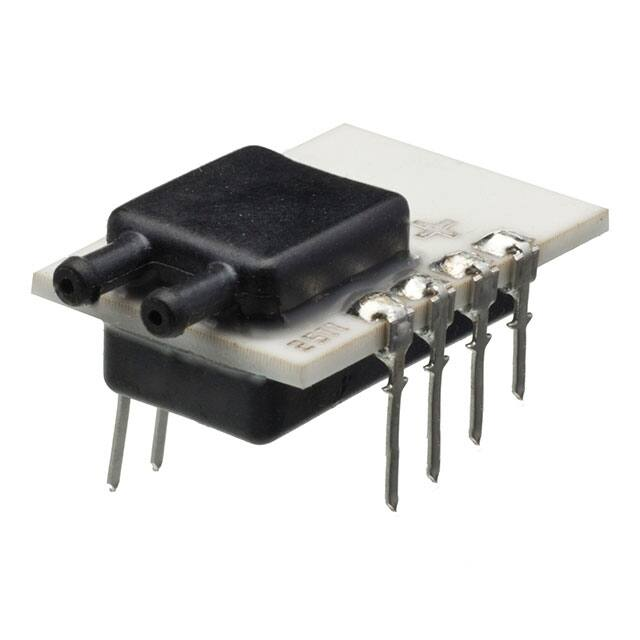
The P1J series of pressure sensors incorporates a piezo-resistive sensing element in a compact package. Using a 2.7 to 5.5 VDC supply voltage, the P1J
provides a SPI or I2C digital output as required by your application. Internal temperature compensation provides and accurate, easy to use sensor. The
industry standard terminal pins provides ease of use for your printed circuit board designs.
Features
• Compact Package
• Amplified Temperature Compensated Digital Output
• No Position Sensitivity above 0-2”H2O
• EMI/RFI and ESD Protected
• Superior Output Signal Stability
• Printed Circuit Board through Hole Mounting
Applications
• Variable Air Volume Systems
• Filter Pressure Monitoring
• Duct Air Flow
• Modulated Furnace Controls
• Combustion Airflow
• Gaseous Leak Detection
• Medical Applications:
Oxygen Concentrators, Ventilators, Anesthesia Equipment, CPAP,
Wound Therapy.
MAIN FEATURES
Pressure Ranges
2, 5, 10, +/-2, +/- 5, +/- 10 inches of water; 5, 12.5, 25, +/- 5, +/- 6, +/- 12.5, +/- 25 mbar
Electrical Connection
PCB thru hole terminal pins, 2.54 mm [.100 inch] pitch
Pressure Connection
Barbed port, 1.9[.08] diameter
Housing Material
PPS, 40% glass filled, black
Terminal Pin Material
Phosphor bronze, tin plated
Supply Voltage
2.7 to 5.5 VDC
Output Signal
14 Bit Digital Output Count – Digital count at null (0% FS): 1638
Digital count at full scale (100% FS) 14745
Page 1
Copyright © 2018 Sensata Technologies, Inc.
www.sensata.com
�TECHNICAL SPECIFICATIONS
Pressure Ranges
from 0 to...
2” H2O
5” H2O
10” H2O
+/- 2” mBar
+/- 5” mBar
from 0 to...
5mbar
12.5mbar
20mbar
+/- 5mbar
+/- 12.5 mbar
Proof Pressure Factor
1.0 PSI/
(70mbar)
1.0 PSI/
(70mbar)
1.0 PSI/
(70mbar)
1.0 PSI/
(70mbar)
1.0 PSI/
(70mbar)
Burst Pressure Factor
1.8 PSI/
(125mbar)
1.8 PSI/
(125mbar)
1.8 PSI/
(125mbar)
1.8 PSI/
(125mbar)
1.8 PSI/
(125mbar)
Physical
Expected Operating Life
10 million full pressure life cycles
Shelf Life
10 years minimum
Stability
+/- 0.5% of full scale span for 1 year
Vibration
10 G’s peak to peak sinusoidal (20 to 1600Hz)
Shock Resistance
Weight
50 G’s ½ Sinewave, 11 mSec pulse, 18 pulses (6 per axis)
3.5g max.
Operating Temperature
-20°C to 85°C
Storage Temperature
-40°C to 85°C
Humidity
Media
Up to 92% RH in a non-condensing environment
Dry air
Performance
Accuracy
0.25% Max (% of full scale span) (RSS of linearity, hysteresis and repeatability)
Temp. Error
0.05%/ C [% of full scale span]
Temp. Error
5% full scale span within temperature range -20° to 0°C and 60° to 85°C 0 to 60°C
Electrical
Input Voltage Protection
Excitation Current
-0.3 to 6 VDC on Vin PIN, -0.3 to Vs+0.3 on all other pins
< 2.5mA
Minimum Load
25k Ohms between output and ground
Response Time
0.5 ms
Page 2
Copyright © 2018 Sensata Technologies, Inc.
www.sensata.com
�DIMENSIONS
Dimensions in mm [Inch]
Page 3
Copyright © 2018 Sensata Technologies, Inc.
www.sensata.com
�I2C COMMUNICATION
Acknowledge (ACK)
Output
Signal Resolution
12 Bits (11 bits minimum for 0-2” H2O and 0-5 mBar range)
Update Rate
0.5 ms
Digital Count at 0% Pressure
Digital Count at 100% Pressure
Sensor Slave Addresses
1638 (10% of 2^14 counts or 0x666)
14745 (90% of 2^14 counts or 0x3999)
40 (0x28), 56 (0x38), 72 (0x48), 88 (0x58), 104 (0x68), 120 (0x78)
SYMBOL
MIN
MAX
UNITS
Analog Supply Voltage to Gnd
VDD
2.7
5.5
V
High-level input voltage
VIH
0.8 × VDD
VDD
V
Low-level input voltage
VIL
0
0.2 × VDD
V
High-level output voltage
VOH
VDD - 0.2
-
V
Low-level output voltage
VOL
-
0.2
V
Output Sourcing Current
IOH_SDA
-1.9
-4.8
mA
Output Sink Current
IOL_SDA
2.3
6.2
mA
200
pF
PARAMETER
Load Capacitance at SDA (@ 400 kHz)
CSDA
Pull-up Resistor
RI2C_PU
Input Capacitance (each pin)
CI2C_IN
Ω
500
10
pF
fSCL
100
400
kHz
tHDSTA
0.1
-
µs
Minimum SCL clock low width 1)
tLOW
0.6
µs
Minimum SCL clock high width 1)
tHIGH
0.6
µs
Start condition setup time relative to
SCL edge
tSUSTA
0.1
µs
Data hold time on SDA relative to SCL
edge
tHDDAT
0
µs
Data setup time on SDA relative to SCL
edge
tSUDAT
0.1
µs
Stop condition setup time on SCL
tSUSTO
0.1
µs
tBUS
2
µs
SCL clock frequency
START condition hold time relative to
SCL range
Bus free time between stop condition
and start condition
1) Combined low and high widths must equal or exceed minimum SCLK period.
Page 4
Copyright © 2018 Sensata Technologies, Inc.
www.sensata.com
�I2C TIMING DIAGRAM
Note
There are three adjustments to the I2C implementation compared with the original I2C™ protocol:
• Sending a start-stop condition without any transitions on the CLK line (no clock pulses in between) creates a communication error for the next
communication, even if the next start condition is correct and the clock pulse is applied. An additional start condition must be sent, which results in
restoration of proper communication.
• The restart condition—a falling SDA edge during data transmission when the CLK clock line is still high—creates the same situation. The next
communication fails, and an additional start condition must be sent for correct communication.
• A falling SDA edge is not allowed between the start condition and the first rising SCL edge. If using an I2C™ address with the first bit 0, SDA must
be held low from the start condition through the first bit.
Page 5
Copyright © 2018 Sensata Technologies, Inc.
www.sensata.com
�SPI COMMUNICATION
Output Packet with Positive Edge Sampling
Packet = [ {S(1:0), B(13:8)}, {B(7:0)}, {T(10:3)}, {T(2:0),xxxxx}] Where
S(1:0) = Status bits of packet (normal, command, busy, diagnostic)
B(13:8) = Upper 6 bits of 14-bit bridge data
B(7:0) = Lower 8 bits of 14-bit bridge data
T(10:0) = NOT corrected temperature data (mask out or terminate read early)
Output
Signal Resolution
12 Bits (11 bits minimum for 0-2” H2O and 0-5 mBar range)
Update Rate
0.5 ms
Digital Count at 0% Pressure
Digital Count at 100% Pressure
1638 (10% of 214 counts or 0x666)
14746 (90% of 214 counts or 0x3999)
SYMBOL
MIN
MAX
UNITS
Analog Supply Voltage to Gnd
VDD
2.7
5.5
V
High-Level Input Voltage
VIH
0.8 × VDD
VDD
V
Low-Level Input Voltage
VIL
0
0.2 × VDD
V
High-Level Output Voltage
VOH
VDD - 0.2
-
V
Low-Level Output Voltage
VOL
-
0.2
V
IOH_MISO
1.9
-4.8
mA
IOH_SS
-0.63
-1.9
mA
IOL_MISO
2.3
6.2
mA
IOL_SS
0.85
3.0
mA
10
pF
PARAMETER
Output Sourcing Current @ VOH
Output Sink Current @ VOL
Input Capacitance (Each Pin)
CI2C_IN
SCLK Clock Frequency (4 MHz clock)
fSCL
50
800
kHz
SCLK Clock Frequency (1 MHz clock)
tSCL
50
200
kHz
SS Drop to First Clock Edge
tHDSS
2.5
µs
Minimum SCL Clock Low Width 1)
tLOW
0.6
µs
Minimum SCL Clock High Width 1)
tHIGH
0.6
µs
Clock Edge to Data Transition
tCLKD
0
Rise of SS Relative to Last Clock Edge
tSUSS
0.1
µs
Bus Free Time Between Rise and Fall of SS
tBUS
2
µs
0.1
µs
1) Combined low and high widths must equal or exceed minimum SCLK period.
Page 6
Copyright © 2018 Sensata Technologies, Inc.
www.sensata.com
�SPI TIMING DIAGRAM
Note
The MISO line is setup to change state on the falling edge of the SCLK clock. Accordingly, the master should sample the data on the rising edge of the
SCLK signal.
I2C/SPI DIAGNOSTIC FEATURES
The P1J offers a full suite of diagnostic features to ensure robust system operation. The diagnostic states are indicated by a transmission of the status
of the 2 MSBs of the bridge high byte data or by a saturated output at 3FFFH.
STATUS BITS (2 MSB’S OF OUTPUT PACKAGE)
Signal resolution
Update rate
Digital count at 0% pressure
Digital count at 100% pressure
DEFINITION
12 Bits (11 bits minimum for 0-2” H2O and 0-5 mBar range)
0.5 ms
1638 (10% of 214 counts or 0x666)
14746 (90% of 214 counts or 0x3999)
When the two MSBs are 11, one of the following faults listed below is indicated.
• Invalid EEPROM signature
• Loss of bridge positive or negative
• Bridge input short
• Loss of bridge source
• Loss of bridge sink
All diagnostics are detected in the next measurement cycle and reported in the subsequent data fetch. Once a diagnostic is reported, the diagnostic
status bits will not change unless both the cause of the diagnostic is fixed and a power-on-reset is performed.
Page 7
Copyright © 2018 Sensata Technologies, Inc.
www.sensata.com
�Example : P1J-2-AX16PA
ORDERING OPTIONS
P1J Pressure sensor 0 -1” H20, I2C 28 Hex digital output, no internal material
seal, barbed tube fitting port with PCB Terminal Pin connection, no external
material seal.
P1J
Family
2
A
X
16
P
A
P1J
Pressure Ranges
2:
2B:
5:
5B:
10:
10B:
5MB:
5MBB:
6MBB:
12.5MB:
12.5MBB:
25MB:
25MBB
0-2” H2O
+/- 2” H2O
0-5” H2O
+/- 5” H2O
0-10” H2O
+/- 10” H2O
0-5 mbar
+/- 5 mbar
+/- 6 mbar
0-12.5 mbar
+/-12.5 mbar
0-25 mbar
+/- 25 mbar
Output Type
8: SPI
A: l2C, 28 HEX
B: l2C, 38 HEX
C: l2C, 48 HEX
D: l2C, 58 HEX
E: l2C, 68 HEX
F: l2C, 78 HEX
Seal Material
X: None
Pressure Connection
16: Barb or Tube Fitting
Built-in Connector
P: PCB Terminal Pins
Seal Material
A: None
Page 8
Copyright © 2018 Sensata Technologies, Inc.
www.sensata.com
�AGENCY APPROVALS & CERTIFICATIONS
Page 9
Revised 2/16/18
Sensata Technologies, Inc. (“Sensata”) data sheets are solely intended to assist designers (“Buyers”) who are developing systems that
incorporate Sensata products (also referred to herein as “components”). Buyer understands and agrees that Buyer remains responsible
for using its independent analysis, evaluation and judgment in designing Buyer’s systems and products. Sensata data sheets have
been created using standard laboratory conditions and engineering practices. Sensata has not conducted any testing other than that
specifically described in the published documentation for a particular data sheet. Sensata may make corrections, enhancements,
improvements and other changes to its data sheets or components without notice.
Buyers are authorized to use Sensata data sheets with the Sensata component(s) identified in each particular data sheet. HOWEVER, NO
OTHER LICENSE, EXPRESS OR IMPLIED, BY ESTOPPEL OR OTHERWISE TO ANY OTHER SENSATA INTELLECTUAL PROPERTY RIGHT, AND
NO LICENSE TO ANY THIRD PARTY TECHNOLOGY OR INTELLECTUAL PROPERTY RIGHT, IS GRANTED HEREIN. SENSATA DATA SHEETS
ARE PROVIDED “AS IS”. SENSATA MAKES NO WARRANTIES OR REPRESENTATIONS WITH REGARD TO THE DATA SHEETS OR USE
OF THE DATA SHEETS, EXPRESS, IMPLIED OR STATUTORY, INCLUDING ACCURACY OR COMPLETENESS. SENSATA DISCLAIMS
ANY WARRANTY OF TITLE AND ANY IMPLIED WARRANTIES OF MERCHANTABILITY, FITNESS FOR A PARTICULAR PURPOSE, QUIET
ENJOYMENT, QUIET POSSESSION, AND NON-INFRINGEMENT OF ANY THIRD PARTY INTELLECTUAL PROPERTY RIGHTS WITH REGARD
TO SENSATA DATA SHEETS OR USE THEREOF.
All products are sold subject to Sensata’s terms and conditions of sale supplied at www.sensata.com SENSATA ASSUMES NO LIABILITY
FOR APPLICATIONS ASSISTANCE OR THE DESIGN OF BUYERS’ PRODUCTS. BUYER ACKNOWLEDGES AND AGREES THAT IT IS SOLELY
RESPONSIBLE FOR COMPLIANCE WITH ALL LEGAL, REGULATORY AND SAFETY-RELATED REQUIREMENTS CONCERNING ITS PRODUCTS,
AND ANY USE OF SENSATA COMPONENTS IN ITS APPLICATIONS, NOTWITHSTANDING ANY APPLICATIONS-RELATED INFORMATION
OR SUPPORT THAT MAY BE PROVIDED BY SENSATA.
Mailing Address: Sensata Technologies, Inc., 529 Pleasant Street, Attleboro, MA 02703, USA.
Copyright © 2018 Sensata Technologies, Inc.
CONTACT US
Americas
+1 (800) 350 2727
sensors@sensata.com
switches@sensata.com
Europe, Middle East & Africa
+359 (2) 809 1826
pressure-info.eu@sensata.com
Asia Pacific
sales.isasia@list.sensata.com
China +86 (21) 2306 1500
Japan +81 (45) 277 7117
Korea +82 (31) 601 2004
India +91 (80) 67920890
Rest of Asia +886 (2) 27602006
ext 2808
www.sensata.com
�


 工商网监
湘ICP备2023018690号
工商网监
湘ICP备2023018690号
