MCDP6000
USB Type-C DP Alt-Mode Switching
Retimer
Datasheet
KDS-MCDP6000-107
Rev. 1.0.7
MegaChips’ Proprietary and Confidential
This information shall not be shared or distributed outside the company and will be exchanged based on the
signed proprietary information exchange agreement. MegaChips reserves the right to make any change
herein at any time without prior notice. MegaChips does not assume any responsibility or liability arising out
of application or use of any product or service described herein except as explicitly agreed upon.
MegaChips’ Proprietary Information – Strictly Confidential
Page 1 of 46
�MCDP6000
USB Type-C DP Alt-Mode Switching Retimer
Contents
1.
Description.................................................................................................................................................. 8
2.
Application Overview .................................................................................................................................. 9
3.
Functional Description .............................................................................................................................. 10
3.1.
System Block Diagram ...................................................................................................................... 10
3.2.
MCDP6000 Block Diagram ............................................................................................................... 11
3.3.
Receiver PHY .................................................................................................................................... 12
3.4.
Transmitter PHY ................................................................................................................................ 13
3.5.
DisplayPort Receiver Interface.......................................................................................................... 14
3.6.
AUX_CH, SBU Interface for DisplayPort Alternate Mode ................................................................. 15
AUX_CH latency mode .............................................................................................................. 16
3.7.
USB 3.2 x1 Interface ......................................................................................................................... 17
3.8.
USB Type-C Connector Facing Interface ......................................................................................... 17
3.9.
IC Operation ...................................................................................................................................... 18
3.9.1.
Bootstrap .................................................................................................................................... 18
3.9.2.
IC Top-Level State Machine ...................................................................................................... 20
3.9.3.
TWI Programmable Mode .......................................................................................................... 21
3.9.4.
Stand-Alone Mode ..................................................................................................................... 21
3.9.5.
Low Power Mode ....................................................................................................................... 21
3.9.6.
USB 3.2 x1 Retimer Operation .................................................................................................. 21
3.9.7.
DisplayPort Retimer Operation .................................................................................................. 23
3.10.
Power Supply ................................................................................................................................ 24
3.11.
Power Consumption ...................................................................................................................... 24
3.12.
System Interface............................................................................................................................ 25
3.12.1.
TWI ......................................................................................................................................... 25
3.12.2.
XTAL Buffer Operation ........................................................................................................... 27
3.12.3.
Reference Clock Input ............................................................................................................ 28
MegaChips’ Proprietary Information –Confidential
Page 2 of 46
�MCDP6000
USB Type-C DP Alt-Mode Switching Retimer
3.12.4.
Reference Clock Output ......................................................................................................... 28
4.
Pin Description ......................................................................................................................................... 30
5.
Package Specification .............................................................................................................................. 34
5.1.
Package Drawing and Dimensions ................................................................................................... 34
6.
Marking Field Template and Descriptors ................................................................................................. 35
7.
Electrical Specifications ............................................................................................................................ 36
7.1.
Absolute Maximum Ratings .............................................................................................................. 36
7.2.
Device Operating Conditions ............................................................................................................ 36
7.3.
Electrical Characteristics ................................................................................................................... 37
7.3.1.
DC characteristics ...................................................................................................................... 37
7.3.2.
DisplayPort transmitter............................................................................................................... 38
7.3.3.
DisplayPort receiver ................................................................................................................... 40
7.3.4.
DisplayPort AUX_CH ................................................................................................................. 41
7.3.5.
USB 3.2 x1 transmitter ............................................................................................................... 42
7.3.6.
USB 3.2 x1 receiver ................................................................................................................... 43
7.3.7.
TWI Timing ................................................................................................................................. 44
8.
Ordering Information ................................................................................................................................ 44
9.
References ............................................................................................................................................... 44
10.
Revision history .................................................................................................................................... 45
MegaChips’ Proprietary Information –Confidential
Page 3 of 46
�MCDP6000
USB Type-C DP Alt-Mode Switching Retimer
List of Tables
Table 1.
DP1.4a Repeater Mode ................................................................................................................... 8
Table 2.
DP transmitter configuration .......................................................................................................... 13
Table 3.
SSC source in each operation mode............................................................................................. 14
Table 4.
AUX_CH latency mode.................................................................................................................. 16
Table 5.
0x350 register definition ................................................................................................................ 16
Table 6.
MCDP6000 Bootstrap operation ................................................................................................... 18
Table 7.
MCDP6000 Bootstrap for AUX_CH latency mode ........................................................................ 18
Table 8.
Operation mode configuration register .......................................................................................... 19
Table 9.
MCDP6000 Operating Mode ......................................................................................................... 20
Table 10.
Power Consumption (Preliminary estimation in typical conditions) ........................................... 24
Table 11.
TWI Device ID Configuration ..................................................................................................... 25
Table 12.
Recommended Crystal Specifications ....................................................................................... 27
Table 13.
Recommended Reference Clock Input Characteristics ............................................................. 28
Table 14.
Reference Clock Output Characteristics.................................................................................... 28
Table 15.
Reference Clock Configuration Register Definition ................................................................... 29
Table 16.
Pin Description ........................................................................................................................... 31
Table 17.
Field Descriptors ........................................................................................................................ 35
Table 18.
Absolute Maximum Ratings ....................................................................................................... 36
Table 19.
Device Operating Conditions ..................................................................................................... 36
Table 20.
DC Characteristics ..................................................................................................................... 37
Table 21.
DisplayPort transmitter characteristics ...................................................................................... 38
Table 22.
DisplayPort receiver characteristics ........................................................................................... 40
Table 23.
USB 3.2 x1 transmitter characteristics ....................................................................................... 42
Table 24.
USB 3.2 x1 receiver characteristics ........................................................................................... 43
Table 25.
TWI Timing ................................................................................................................................. 44
Table 26.
Document revision history ......................................................................................................... 45
MegaChips’ Proprietary Information –Confidential
Page 4 of 46
�MCDP6000
USB Type-C DP Alt-Mode Switching Retimer
List of Figures
Figure 1.
MCDP6000 System Block Diagram ............................................................................................. 7
Figure 2.
MCDP6000 Motherboard-Down Use Case.................................................................................. 9
Figure 3.
MCDP6000 System Block Diagram ........................................................................................... 10
Figure 4.
MCDP6000 Block Diagram ........................................................................................................ 11
Figure 5.
FSM Based Eye Scan Concept ................................................................................................. 12
Figure 6.
Example Output of Software Based Eye Scan .......................................................................... 13
Figure 7.
AUX – SBU channel topology .................................................................................................... 15
Figure 8.
MCDP6000 Operation Mode State Machine ............................................................................. 20
Figure 9.
Write Access .............................................................................................................................. 26
Figure 10.
Read Access .............................................................................................................................. 26
Figure 11.
Internal Oscillator with an External Crystal ................................................................................ 27
Figure 12.
Cascading Reference Clock Across Multiple MCDP6000 ......................................................... 29
Figure 13.
MCDP6000 Ex-VQFN46 Pin Assignment (Top-View) ............................................................... 30
Figure 14.
MCDP6000 Ex-VQFN46 Package Outline Drawing (unit: mm) ................................................. 34
Figure 15.
MCDP6000 Ex-VQFN46 Marking Template .............................................................................. 35
MegaChips’ Proprietary Information –Confidential
Page 5 of 46
�MCDP6000
USB Type-C DP Alt-Mode Switching Retimer
o
Features
•
•
•
−
Integrated USB Type-C DisplayPort alternate
mode lane switch to support
−
Flip-ability of USB Type-C
−
Simultaneous USB 3.2 x1 Enhanced
SuperSpeed (ESS) and 2 lane DP1.4a
−
4/2/1-Lane
DP1.4a(RBR/HBR/HBR2/HBR3)
•
CTLE for SS
Support of custom PHY configuration
through TWI (Two Wire Interface)
DP1.4a Compliant Repeater
−
Data rate 1.62 Gbps / 2.7 Gbps / 5.4
Gbps / 8.1 Gbps
−
LT-tunable repeater
−
Transparent mode / Non-transparent
mode support
Power Supply Voltages
−
AUX_CH transaction snooping
−
−
DP1.4a Compliant Retimer DPCD
registers
−
8b/10b coding
−
Pattern generator and Error Checker
−
Down-spreading of link clock
−
Error detection
−
Adjustable TXEQ during the link training
through AUX_CH
−
Adaptive equalizer with CTLE and DFE
o DFE + CTLE for HBR3
o CTLE for HBR2 / HBR / RBR
−
Support of custom PHY configuration
through TWI
1.8 V for I/O, 1.2 V for core
USB3.2 Appendix.E x1 Compliant Retimer
−
5 Gbps and 10 Gbps support
−
Link training participation
−
Spread-spectrum clocking as per USB 3.2
standard
−
LFPS polling and processing
−
LFPS Based PWM support
−
Pass-Through / Local loopback
−
Loopback BERT for USB 3.2 SS
−
Lane polarity inversion
−
BLR (Bit-Level Retimer) for SS mode
o Low latency data path
o Link layer snooping
▪ 8b/10b coding
▪ De-scrambler
▪ Link power management
support
−
−
−
SRIS (Separate Reference clock
Independent SSC) for SSP mode
o 128b/132b coding
o Scrambler / De-scrambler
o Link power management support
o SKP OS handling / Elastic buffer
for USB for clock offset
compensation
o DC balance tracking / control
o Error correction
Transmitter Emphasis
o 3-tap FIR TXEQ for SSP
o 2-tap TXEQ for SS
•
Real time Eye Opening Monitor (EOM)
•
TWI slave to configure the integrated lane
mapping and operation mode
−
Compatible with I2C master
−
Support up to 4 unique TWI device ID
•
Configuration pins for the integrated lane
switch and operation mode
•
Low Power Operation
•
•
−
520 mW in USB 3.2 x1 SSP + Two lanes
of DisplayPort HBR3 operation with 1.2 V
and 1.8 V power supply
−
850 uW in standby mode
ESD Specification
−
HS Signals : 1 KV HBM
−
Low-Speed Signals : 2 KV HBM
Package
−
Adaptive Receiver Equalization
o DFE + CTLE for SSP
46 Ex-VQFN (6.5 mm x 4.5 mm)
MegaChips’ Proprietary Information –Confidential
Page 6 of 46
�MCDP6000
USB Type-C DP Alt-Mode Switching Retimer
Applications
Desktop PC / Notebook / Tablet /
Smartphone motherboard enabling USB
Type-C DP alternate mode
Figure 1.
MCDP6000 System Block Diagram
USB host /
Device
D+/-
SBU1/2
On / off
switch
AUX_CH
HPD
From battery
To each components
Power
Management
Unit
Vbus
MegaChips’ Proprietary Information –Confidential
Page 7 of 46
CC/Vcon
n switch
CC
I2C or Conf. pins
PD control /
Plug
orientation
Vconn
Type-C receptacle
SSRX
MCDP6000
SSTX
ML x 4
DP source
•
�MCDP6000
USB Type-C DP Alt-Mode Switching Retimer
1. Description
The MCDP6000 is a low power USB 3.2 x1 and DisplayPort1.4a repeater device with an integrated USB
Type-C switch targeted for desktop / mobile PC motherboard-down application.
The USB 3.2 x1 retimer supports both SuperSpeed (SS) bit rate (5 Gbps), and SuperSpeedPlus (SSP) data
rate (10 Gbps). The USB 3.2 x1 retimer includes the link layer function and LTSSM and RTSSM to
participate in the link training. The MCDP6000 supports SS mode with a BLR (Bit-Level Retimer) and SSP
mode with a SRIS (Separate Reference clock Independent SSC). The MCDP6000 supports link power
management with Ux entry and exits in both SS and SSP modes. In addition, the MCDP6000 supports the
link state and link quality maintenance, compensates the clock offset between the downstream port and the
upstream port, detects errors, and corrects single symbol errors in framing order sets, single bit block header
errors, and single or double-bit SKP symbol errors in SSP mode. It also supports spread spectrum clocking
(SSC) to minimize EMI and the low frequency periodic signaling (LFPS). The transmitter employs 3-tap FIRbased transmitter equalizer for SSP operation and fixed transmitter equalizer ranging from 3 dB to 4 dB for
SS operation. The receiver employs an adaptive Continuous Time Linear Equalizer (CTLE) and a Decision
Feedback Equalizer (DFE). Both the transmitter equalizer and the receiver equalizer are configurable
through the TWI register. Proper settings to comply with USB 3.2 electrical requirements are provided by
default.
The DP1.4a repeater supports 1.62 Gbps, 2.7 Gbps, 5.4 Gbps, and 8.1 Gbps data rates. The following use
cases are supported.
Table 1.
DP1.4a Repeater Mode
Mode
AUX_CH Function
Non-transparent mode
Sample, Manipulate, and
Forward to snoop or respond
as defined in DP1.4a
standard.
Transparent mode
Sample and Forward to snoop
LT tunable PHY Repeater
The DP1.4a repeater implements AUX_CH snooping function of DPCD addresses defined in the standard as
well as the LT-tunable PHY Repeater DPCD registers. The DP1.4a repeater can support up to a 0.5% downspread link rate. The transmitter employs TXEQ, which adjusts its pre-emphasis level according to either the
AUX_CH transaction during the link training or the TWI. The receiver employs a fully adaptive Continuous
Time Linear Equalizer (CTLE) and Decision Feedback Equalizer (DFE). The transmitter parameter can be
set to support the amplitude level and the pre-emphasis level defined in DP1.4a standard are provided in
default.
MegaChips’ Proprietary Information –Confidential
Page 8 of 46
�MCDP6000
USB Type-C DP Alt-Mode Switching Retimer
The MCDP6000 operating mode can be configured through the TWI by default. It can be optionally
configured through the 3 configuration pins by enabling the feature through TWI. These interfaces can be
controlled from an external Power Delivery (PD) controller or microcontroller to set the plug orientation and
the pin mapping of the USB Type-C DP Alt-mode. The MCDP6000 operates at 1.8 V and 1.2 V.
The power consumption is:
1. 520 mW with an active 4 lane retimer (USB 3.2 x1 SSP TX/RX and DP 2 lanes HBR2)
2. 850 uW in stand-by state
The MCDP6000 is offered in a 46-pin, 6.5 mm x 4.5 mm Ex-VQFN package.
2. Application Overview
The target application of MCDP6000 is the Desktop PC / Notebook / Tablet / Smartphone motherboard
enabling USB Type-C DP alternate mode.
The MCDP6000 resides next to the DisplayPort source (CPU/GPU) device, the USB 3.x host or dual-role
device, and the Power Delivery (PD) controller on a same PCB with copper tracks connecting directly to
these devices. High speed serial interface tracks are typical microstrip lines with controlled impedance of 100
ohm. The MCDP6000 communicates with these devices through either TWI, 3 configuration pins or
AUX_CH. By default, the operating mode and the plug orientation are controlled by the PD controller or the
Embedded Controller (EC) through the TWI. When the DisplayPort link is discovered by the PD controller,
the link training is initiated by the DP source through the AUX_CH.
Figure 2.
Motherboard
MCDP6000 Motherboard-Down Use Case
PD
controller
SoC
USB
3.1
USB Type-C Cable
DP sink
and / or
USB3.1 device
DP
source
MCDP6000
MegaChips’ Proprietary Information –Confidential
Page 9 of 46
�MCDP6000
USB Type-C DP Alt-Mode Switching Retimer
3. Functional Description
This section describes the following operations of the MCDP6000:
1. System block diagram
2. MCDP6000 block diagram
3. Receiver PHY
4. Transmitter PHY
5. DisplayPort main link receiver interface
6. AUX_CH / SBU interface
7. USB 3.2 x1 interface
8. USB Type-C connector facing interface
9. IC operation
10. Power supply
11. Power consumption
12. System interface
3.1. System Block Diagram
Figure 3.
MCDP6000 System Block Diagram
Motherboard
CPU
1.8V
1.2V
V18
V12
USB SSRX
USB SSRX
RX2
USB SSTX
USB SSTX
TX2
RX2
TX2
TX1
TX1
DP ML0
DP ML0
DP ML1
DP ML1
DP ML2
DP ML2
DP ML3
DP ML3
AUX_CH
AUX_CH
HPD
RX1
RX1
MC
60
DP
SBU
On / off
switch
SBU
00
CC
VCONN
CC/VCONN
Switch (FET)
GND
XTAL
TWI
VBUS
Conf
PD
controller
Power
Management Unit
To MB
MegaChips’ Proprietary Information –Confidential
Page 10 of 46
�MCDP6000
USB Type-C DP Alt-Mode Switching Retimer
3.2. MCDP6000 Block Diagram
Figure 4.
MCDP6000 Block Diagram
{P_POL,P_CONF[1:0]} SDA SCL
Config
TWI slave
AUX
_CH
AUX interpreter
RxEQ
RxEQ
AUX_CHp/
n
TX1p/n
TxEQ
RxEQ
ML3p/n
TX2p/n
TxEQ
RxEQ
ML2p/n
TxEQ
RxEQ
ML1p/n
RX2p/n
TxEQ
RxEQ
ML0p/n
RxEQ
RxEQ
SSTxp/n
RxEQ
SSRxp/n
Switch / USB 3.1 Link layer / DP1.3 PHY logical layer
TxEQ
Resister bank
AUX
_CH
RX1p/n
SBU1/2
XTAL
The figure above shows a block diagram of the MCDP6000. The MCDP6000 includes the following blocks.
The details of each block are described in the following sections:
1. Receiver PHY
2. Transmitter PHY
3. DisplayPort receiver interface
4. AUX_CH
5. USB 3.2 x1 (Gen1 and Gen2) interface
6. USB Type-C connector facing interface
7. TWI
8. Configuration pins
9. USB Type-C switch fabric
10. Crystal Interface for reference clock
MegaChips’ Proprietary Information –Confidential
Page 11 of 46
�MCDP6000
USB Type-C DP Alt-Mode Switching Retimer
3.3. Receiver PHY
The receiver PHY of the MCDP6000 employs CTLE and DFE with adaptive equalization logic, CDR block, a
serial to parallel conversion block, and an eye opening monitor (EOM) block. The termination register of the
receiver is calibrated to a differential of 100 ohm by default. Depending on the impedance of PCB track, the
termination can be programmed to 80 ohm.
CTLE’s degeneration resistance is tunable for up to 40 steps, which corresponds to 0 dB to 16 dB peaking at
5 GHz (in a typical case). The CTLE capacitance is fixed by default.
Both the CTLE degeneration resistance and each DFE TAP value are automatically adapted to channel
characteristics during the link training. By default, the adaptation time is set to a few hundred microseconds
for CTLE and up to 1.5 milliseconds for DFE.
The MCDP6000 supports the real time eye opening monitor (EOM) in the background. EOM can use two
different methods:
•
FSM based observation of four sampling points which detects a lower BER than the configured
threshold
•
Scans all sampling points by software implementation
Figure 5.
FSM Based Eye Scan Concept
MegaChips’ Proprietary Information –Confidential
Page 12 of 46
�MCDP6000
USB Type-C DP Alt-Mode Switching Retimer
The figure above shows a concept of the FSM based EOM method. THRmax and THRmin indicate the
vertical range to operate in less than 1E-9 BER. PHOSmin and PHOSmax indicate the horizontal range to
operate in less than 1E-9 BER.
Scanning full range is also possible by software. The figure below is an example of a software based EOM.
Figure 6.
Example Output of Software Based Eye Scan
3.4. Transmitter PHY
The MCDP6000 transmitter supports up to 1000 mVpp diff swing without emphasis. The MCDP6000
supports up to 12 dB pre-emphasis. The MCDP6000 uses pre-programmed parameter sets to be compliant
with USB and DP standards. The table below shows a combination of the voltage swing levels and the preemphasis level which the MCDP6000 supports for DP.
Table 2.
Voltage
Swing
Level
DP transmitter configuration
Pre-emphasis Level
0
1
2
3
0
Support
Support
Support
Support
1
Support
Support
Support
Not Support
2
Support
Support
Not Support
Not Support
3
Support
Not Support
Not Support
Not Support
The amplitude level, pre-shoot, and the de-emphasis level for USB follow a standard requirement. As
defined in the USB standard, the MCDP6000 supports a low power transmitter; the amplitude is decreased
up to a 400 mVpp diff as an option.
MegaChips’ Proprietary Information –Confidential
Page 13 of 46
�MCDP6000
USB Type-C DP Alt-Mode Switching Retimer
The MCDP6000 transmitter uses the clock from a phase interpolator. The phase interpolator generates a
modulated clock to support SSC (Spread Spectrum Clocking). The table below shows the origin of the SSC
generator in the MCDP6000 operation modes. Since DP and USB SS operates as a BLR (Bit Level
Retimer), which does not support an elasticity buffer to compensate for the clock offset, the transmitter clock
has to be synchronized with the receiver clock.
Table 3.
Mode
SSC source in each operation mode
SSC Source
SSC Profile
DP
From Recovered Clock
Depends on connected
device
USB SS
From Recovered Clock
Depends on connected
device
USB SSP
Local SSC Generator
Triangle profile
3.5. DisplayPort Receiver Interface
The MCDP6000 receives audio-video streams (DisplayPort) from a source device via the DisplayPort link
(DP Link). The DP link comprises 4 main lanes and an AUX CH. The MCDP6000 does not implement an
HPD interface. PD controller configures the MCDP6000 operating mode when it detects the DP alternate
mode and converts the HPD state message to the HPD signal for DP source device. Both main link and AUX
signals are AC-coupled at the source side.
When the MCDP6000 is configured to DP mode, the MCDP6000’s AUX_CH polarity is determined by the
P_POL signal set by PD controller according to the plug orientation. Once the AUX_CH polarity is properly
configured, the MCDP6000 supports the link training to establish the main link as defined in the DisplayPort
standard.
The MCDP6000 provides the receiver status monitor registers through the TWI. Those registers can be
accessed by reading the repeater DPCD field through AUX_CH when the MCDP6000 is in non-transparent
mode.
The MCDP6000 receiver includes an adaptive equalizer so that the receiving signal is properly equalized
during the channel equalization phase. The adaptation is enabled when the TRAINING_PATTERN_SELECT
of DPCD ‘h00102 in transparent mode, or the corresponding repeater DPCD field in non-transparent mode,
is TPS2, TPS3, or TPS4.
MegaChips’ Proprietary Information –Confidential
Page 14 of 46
�MCDP6000
USB Type-C DP Alt-Mode Switching Retimer
3.6. AUX_CH, SBU Interface for DisplayPort Alternate Mode
The DisplayPort Aux channel is a half-duplex bidirectional, AC-coupled, doubly-terminated differential pair. It
is capable of transmitting and receiving bits at 1 Mbps. The AUX channel is used for link management and
device control and handles the following functions:
1. Link training
2. Exchanging DPCD
The MCDP6000 is compliant with DPCD Rev. 1.4. The pull-down termination on AUX_CHp and the pull-up
termination on AUX_CHn are used by the DisplayPort receiver device for the plug detection. Therefore a 2:2
crossbar switch is required on SBU line between the termination resistors and the USB Type-C receptacle.
Figure 7.
AUX – SBU channel topology
Motherboard
DP Source
MCDP6000
TX
RX
TX
AUX Handler
RX
Note:
TX
RX
The termination resistors next to the DP source may not be required when DP source integrates
these resistors.
The MCDP6000 adjusts its main link transmitter amplitude level and pre-emphasis level according to the
DPCD transaction of ‘h00103 – ‘h00106, ‘h00206 and ‘h00207 in the transparent mode or equivalent PHY
repeater DPCD address in the non-transparent mode. The transmitter can be also configured via TWI.In
addition, the MCDP6000 monitors DPCD ‘h00100 – ‘h00101 to decide the bit rate and the lane configuration
as well as ‘h00102 to enable the receiver equalizer adaptation process.
The MCDP6000’s DP receiver status can be obtained through DPCD in the topology of Figure 7. The
snooped information can be also read through the TWI.
MegaChips’ Proprietary Information –Confidential
Page 15 of 46
�MCDP6000
USB Type-C DP Alt-Mode Switching Retimer
AUX_CH latency mode
The MCDP6000 provides two AUX_CH latency modes, low latency mode and normal latency mode. The
summary of the differences between two modes are described in Table 4. AUX_CH latency mode can be
preconfigured by the bootstrap as described in section 3.9.1. It can be also configured through 0x350
register configuration.
Table 4.
AUX_CH latency mode
mode
AUX_CH bit UI tolerance
AUX_CH propagation delay
Low latency
0.5UI -10%/+5%
15-us for round trip
Normal latency
0.5UI +/-20%
100-us for round trip
Table 5.
0x350
0x350 register definition
RETIMER_CONFIG
RW
Default: 0xF
BIT
BIT NAME
FUNCTION
3:0
DP_RXEQ_CONT
DP Rx EQ adaptation option for [0] RBR, [1] HBR, [2] HBR2, [3] HBR3
0: Rx EQ adaptation during TPS2-4
1: Rx EQ adaptation during TPS2-4 and the beginning of Video stream
6:4
RTMR_DP_AUX_CONFIG
3’h0: Low latency mode when TWISLV1 bootstrap is low
3’h1: Normal latency mode
3’h2: Snoop mode
The others: reserved
8:7
Reserved
Reserved
9
RETIMER_CONFIG_RW9
Bootstrap override enable for RTMR_DP_AUX_CONFIG[0]
31:10
Reserved
Reserved
When the MCDP6000 is embedded in DPRX system operating in the transparent mode of LTTPR, the
AUX_CH propagation delay needs to be as part of the AUX_CH response time from the DPRX device. (e.g.
in normal latency mode, 50-us is already added when the DPRX device received the AUX_CH request from
DPTX and another 50-us is added when the DPTX detects DPRX response. Therefore AUX_CH response
MegaChips’ Proprietary Information –Confidential
Page 16 of 46
�MCDP6000
USB Type-C DP Alt-Mode Switching Retimer
should be prepared within 200-us by DPRX. Otherwise, DPRX should respond with AUX_DEFER by 200-us
timer timeout.)
When the MCDP6000 is embedded in DPTX system operating in the transparent mode of LTTPR, it is
recommended to configure the MCDP6000 to the normal latency mode and configure the AUX_CH response
timeout timer to 500-us instead of 400-us.
When the MCDP6000 is cascaded in the active cable, it is recommended to configure the MCDP6000 at the
DPRX side to the normal latency mode and the other to the low latency mode.
3.7. USB 3.2 x1 Interface
The MCDP6000 receives and transmits USB 3.2 x1 Gen1 and Gen2 bit rate stream. The USB link comprises
a receiver lane and a transmitter lane.
The MCDP6000 USB 3.2 x1 receiver includes an adaptive equalizer so that the receiving signal is properly
equalized during the channel equalization phase. The adaptation is enabled when the RTSSM (Retimer
Training and Status State Machine) enters the Polling.RxEQ state. The MCDP6000 configures the preemphasis setting according to whether it is SS bit rate or SSP bit rate.
3.8. USB Type-C Connector Facing Interface
The MCDP6000 USB Type-C connector facing interface (Type-C IF) consists of two lanes of bi-directional
high speed interface, two lanes of a high speed transmitter and a Side Band Use (SBU) bi-directional
interface, which is mainly for AUX (auxiliary channel) communication in the DP alternate mode.
The MCDP6000 Type-C receiver implementation is the same as the one in the USB 3.2 x1 interface except
for the multiplexing capability with the transmitter.
The MCDP6000 Type-C transmitter implementation uses the same building block as a USB 3.2 x1 interface.
The Type-C transmitter supports a DP transmitter in addition to the USB 3.2 x1 transmitter. While the USB
3.2 x1 transmitter uses fixed parameters, the DP transmitter changes its transmitter parameters according to
the adjustment request from a sink device during the link training.
MegaChips’ Proprietary Information –Confidential
Page 17 of 46
�MCDP6000
USB Type-C DP Alt-Mode Switching Retimer
3.9. IC Operation
3.9.1. Bootstrap
Table 6.
MCDP6000 Bootstrap operation
Bootstrap
P_CONF0
P_CONF1
Description
00
0
0
MCDP6000 enters low power mode upon the power-up.
01
1
0
MCDP6000 enters USB 3.2 x1-only mode upon the
power-up.
Table 7.
MCDP6000 Bootstrap for AUX_CH latency mode
TWISLV1
Description
0
Low latency mode
1
Normal latency mode
When the bootstrap is 00, the external pin control is enabled. To change the control mode to TWI control
mode, the following bits should be set to 1:
•
OPMODE_CONF.PPOL_BS_OVR
•
OPMODE_CONF.PCONF0_BS_OVR
•
OPMODE_CONF.PCONF1_BS_OVR
MegaChips’ Proprietary Information –Confidential
Page 18 of 46
�MCDP6000
USB Type-C DP Alt-Mode Switching Retimer
Table 8.
0x504
Operation mode configuration register
OPMODE_CONF
Chip configuration
BIT
BIT NAME
FUNCTION
0
Reserved
Reserved
1
PPOL_OVR_EN
P_POL_OVR_EN, 0: GPIO setting, 1: TWI setting
2
PCONF0_OVR_EN
P_CONF0_OVR_EN, 0: GPIO setting, 1: TWI setting
3
PCONF1_OVR_EN
P_CONF1_OVR_EN, 0: GPIO setting, 1: TWI setting
4
PPOL
P_POL
5
PCONF0
P_CONF0
6
PCONF1
P_CONF1
7
Reserved
Reserved
8
IC_SOFT_RST
0: Normal operation
1: Reset whole IC
9
USB_SOFT_RST
0: Normal operation
1: Reset USB data path
10
DP_SOFT_RST
0: Normal operation
1: Reset DP data path
11
DP_AUX_SOFT_RST
0: Normal operation
1: Reset DP AUX_CH logic
12
PPOL_BS_OVR
Bootstrap override enable for P_POL
13
PCONF0_BS_OVR
Bootstrap override enable for P_CONF0
14
PCONF1_BS_OVR
Bootstrap override enable for P_CONF1
31:15
Reserved
Reserved
MegaChips’ Proprietary Information –Confidential
Page 19 of 46
RW
�MCDP6000
USB Type-C DP Alt-Mode Switching Retimer
3.9.2. IC Top-Level State Machine
The figure below shows the state machine to control the MCDP6000. This state machine changes the
MCDP6000 operation mode based on the configuration registers or pins. The MCDP6000 provides two
options to trigger the state change as explained in Section 3.9.3 and Section 3.9.4.
Figure 8.
MCDP6000 Operation Mode State Machine
Power-On Reset
USB3.1+DP1.3
Retimer
Init
{P_CONF1,0}=11
or directed
PORN=1
{P_CONF1,0} !=11
or directed
Bootstrap = 00
{P_CONF1,0}=11
or directed
POR Done
Low Power
POR power-down
{P_CONF1,0}=10
or directed
{P_CONF1,0}=01
or directed
{P_CONF1,0} !=10
or directed
{P_CONF1,0} =00
or directed
DP1.3 Retimer
USB3.1 Retimer
{P_CONF1,0}=10
or directed
Table 9.
MCDP6000 Operating Mode
P_POL
{P_CONF1, P_CONF0}
Description
Don’t care
{0,0}
Low power mode. (All blocks are powered down except configuration
pins and TWI slave.)
0
{0,1}
USB only (normal orientation)
1
{0,1}
USB only (flipped orientation)
0
{1,0}
DisplayPort 4 lane; pin assignment C (normal orientation)
1
{1,0}
DisplayPort 4 lane; pin assignment C (flipped orientation)
0
{1,1}
USB + DisplayPort 2 lane; pin assignment D (normal orientation)
1
{1,1}
USB + DisplayPort 2 lane; pin assignment D (flipped orientation)
MegaChips’ Proprietary Information –Confidential
Page 20 of 46
�MCDP6000
USB Type-C DP Alt-Mode Switching Retimer
3.9.3. TWI Programmable Mode
The MCDP6000 operation mode should be controlled through the TWI programming interface in default. The
default state after the power-on is the USB 3.2 x1 Only mode. The MCDP6000 changes its state according
to the directives from the policy engine through TWI.
3.9.4. Stand-Alone Mode
The MCDP6000 also provides the three configuration pins for its operation mode. By enabling this feature
through TWI, P_POL and P_CONF0/1 pins can be used to determine the operating mode. These pins
provide the controllability for the USB Type-C plug orientation and the pin assignment to users. The function
of P_POL and P_CONF0/1 is shown in the table below.
Note:
P_POL, P_CONF0 and P_CONF1 I/Os are designed to operate under 1.8 V in nominal case.
Connecting these I/O with 3.3 V output buffer would cause damage.
3.9.5. Low Power Mode
The MCDP6000 enters into the low power mode when P_CONF0/1 is set to 2’b00. Upon the power-up,
P_CONF should be 2’b00 for the lowest power consumption. Only P_CONF, P_POL, the TWI slave and the
register banks in always power-on domain are enabled in the low power mode. The MCDP6000 can be
programmed through the TWI for any required changes in the configuration of low power mode. When the
operating mode changes from other states to the low power mode, the MCDP6000 goes through the reset
cycle except for the register bank in always power-on domain.
The far-end termination detection of USB 3.2 x1 is not performed in the low power mode. In addition, the
receiver termination is not present; for example, the high impedance is present on the transmitter channel,
so that the USB link partner recognizes the missing USB link connection.
3.9.6. USB 3.2 x1 Retimer Operation
The MCDP6000 enters USB 3.2 x1-only mode during power-on-reset. Otherwise, the MCDP6000 enables
the USB 3.2 x1 retimer when P_CONF0 is set to 1’b1.
The MCDP6000 starts far-end termination detection upon the activation of the USB 3.2 x1 retimer until the
receiver termination on the link partner is detected. Unless the MCDP6000 is directed to transit to the low
power state via P_CONF pins or detects the far-end receiver termination, the MCDP6000 stays in the
RX.detect state as described in the USB 3.2 x1 standard.
The MCDP6000 operates as BLR (Bit-Level Retimer) in SS mode and as SRIS (Separate Reference Clock
Independent SSC) in SSP mode.
MegaChips’ Proprietary Information –Confidential
Page 21 of 46
�MCDP6000
USB Type-C DP Alt-Mode Switching Retimer
Note for PHY Capability LBPM handling
The MCDP6000 does not reset b4-b6 in PHY Capability LBPM while the received LBPMs are forwarded. If
the connected UFP device and DFP device are USB 3.2 x2 capable, LBPM handshake between the UFP
device and the DFP device will be established while the MCDP6000 stays Polling.SpeedDetect state. The
LTSSM in the UFP device and the DFP device will detect the tPollingActiveTimeout in Polling.Active state,
then both devices will restart the next link training with Gen2 x 1 configuration.
BLR for SS mode
The BLR minimizes the propagation delay of the retimer data path while it still snoops the link commands and
a few other LMP (Link Management Packet) to participate in the link configuration process and the link power
management.
During the link training, the BLR transmitter may or may not enable SSC. The transmitter clock is synchronized
with the recovered clock in the Polling.TSx state.
The transmitter clock is synchronized with the recovered clock through a low pass filter of the phase code. As
this filter’s cut-off frequency is lower, the frequency to show the jitter transfer becomes lower. The filter
bandwidth is pre-programmed at 1 MHz.
SRIS for SSP mode
The SRIS transmits the data with its own reference clock independent of the recovered clock. Therefore, the
transmitter data does not include the jitter from the receiver side. The elasticity buffer compensates the clock
offset between the receiver and the transmitter by removing or adding SKP symbols.
The MCDP6000 also supports the synchronization of the transmitter clock with the recovered clock. In this
mode, the low frequency jitter is transferred, but the SKP symbol removal or addition rarely occurs since the
clock offset is not expected.
MegaChips’ Proprietary Information –Confidential
Page 22 of 46
�MCDP6000
USB Type-C DP Alt-Mode Switching Retimer
3.9.7. DisplayPort Retimer Operation
The MCDP6000 operates as the DisplayPort 2 lane or 4 lane LT-tunable PHY repeater at the DisplayPort bit
rate of RBR, HBR, HBR2 and HBR3 when the P_CONF1 is set to 1’b1. The default is transparent mode as
defined in DisplayPort1.4a standard. The MCDP6000 can be set to non-transparent mode by writing AAh to
F0003h of the DPCD address. Non-transparent mode is allowed only when the DPCD revision is DPCD Rev.
1.4 or higher.
The HPD signal is not routed to the MCDP6000. The MCDP6000 transitions to the DP sink detected state
when P_CONF1 is set to 1’b1. The MCDP6000 supports DPCD version 1.4.
The MCDP6000 supports transparent mode and non-transparent mode.
Transparent Mode
The transparent mode is the default operating mode of the MCDP6000 when the DisplayPort alternate mode
is enabled and the MCDP6000 is used in the topology shown in Figure 7.
The MCDP6000 starts charging the AC coupling capacitors on the transmission lines of the main links and
AUX_CH as soon as P_CONF1 is set to 1’b1.
The MCDP6000 snoops some link configuration registers the same way as in snooping mode. However, the
MCDP6000 manipulates the received ADJUST_REQUEST_LANEx message from the sink device according
to its receiver link training status. When the MCDP6000 receiver is trained while the sink device receiver is
still not trained, the MCDP6000 manipulates the received ADJUST_REQUEST_LANEx message so that the
source device does not change the transmitter parameter. When the receiver of the MCDP6000 is not
trained when it receives the adjusted request, the MCDP6000 manipulates the received
ADJUST_REQUEST_LANEx based on its preprogrammed adjust request sequence.
The MCDP6000 manipulates TRAINING_LANEx_SET from the source device to be consistent with its
manipulation of ADJUST_REQUEST_LANEx.
The MCDP6000 changes its transmitter configuration based on the ADJUST_REQUEST_LANEx field, which
determines the DPTX’ voltage swing level and pre-emphasis magnitude.
Non-Transparent Mode
The MCDP6000 operates as defined in the section of the LT-tunable PHY repeater of DisplayPort1.4a.
MegaChips’ Proprietary Information –Confidential
Page 23 of 46
�MCDP6000
USB Type-C DP Alt-Mode Switching Retimer
3.10. Power Supply
The MCDP6000 supports 1.8V and 1.2V supplies.
Note:
There is no relationship between 1.8 V ramp-up timing and 1.2 V ramp-up timing. 1.2 V can be
supplied earlier than 1.8 V. Each power supply ramp-up time shall be between 200-us and 20-ms.
3.11. Power Consumption
Table 10.
Power Consumption (Preliminary estimation in typical conditions)
IC Operation Mode
State
Power Consumption (mW)
Low Power Mode
Low Power Mode
0.85
USB 3.2 x1 Only
RX.detect
0.85
USB 3.2 x1 Only
U0
290
USB 3.2 x1 Only
U1
160
U2 (default)
3.2
U2 (lower power U2 mode)
0.85
USB 3.2 x1 Only
U3
0.85
DisplayPort 4 lane DP_BR
(HBR3)
D0 power state
460
DisplayPort 4 lane DP_BR
(HBR3)
D3 power state
10
USB + DisplayPort 2 lane
DP_BR
Combination of USB 3.2 x1
state and DisplayPort 2
lane DP_BR state
520
USB 3.2 x1 Only
MegaChips’ Proprietary Information –Confidential
Page 24 of 46
�MCDP6000
USB Type-C DP Alt-Mode Switching Retimer
3.12. System Interface
3.12.1.
TWI
The TWI slave is intended for an external host controller to configure the MCDP6000 registers for certain use
cases. TWI is accessible in any operating mode. The TWI is compatible with I2C master device.
Note:
SDA and SCL shall be pulled up to 3.3 V.
TWISLV0 and TWISLV1 are designed to operate under 1.8V in nominal case. Connecting these I/O
with a 3.3 V output buffer would cause damage.
TWI Device ID
The TWI of the MCDP6000 operates as the slave. Four device IDs can be supported. Each device’s ID is
determined by the TWISLV0 and TWISLV1 pins as shown in the table below. The TWISLV0/1 pull-up/down
status is detected by the MCDP6000 during the power-up sequence.
Table 11.
TWI Device ID Configuration
TWISLV1
TWISLV0
Slave ID
Pulled down to Ground
Pulled down to Ground
0x14
Pulled down to Ground
Pulled up to 1.8V
0x15
Pulled up to 1.8V
Pulled down to Ground
0x16
Pulled up to 1.8V
Pulled up to 1.8V
0x17
TWI Read / Write Access
The TWI access to the MCDP6000 is 32-bit write or read. All register accesses are on 32-bit word
boundaries. Address auto-increment is also allowed on 32-bit word boundary. Stop / Repeated start can be
used to change the base address to a new address definition.
The figure below shows typical write access:
1.
Master sends Slave ID with write access.
2.
Master sends lower byte of 16-bit register address.
3.
Master sends higher bytes of 16-bit register address.
MegaChips’ Proprietary Information –Confidential
Page 25 of 46
�MCDP6000
USB Type-C DP Alt-Mode Switching Retimer
4.
Master sends data bytes to be written in order of lower byte to higher byte.
Figure 9.
Write Access
SCL
Master to Slave
SDA
Cycle
Slave to Master
Start
SlaveID
A6
RW_ADDR[7:0]
A0
W ACK A7
DATAn[7:0]
RW_ADDR[15:8]
A0 ACK A15
DATAn[15:8]
D7
A8
ACK
DATAn[23:16]
D0 ACK D15
D8 ACK D23
DATAn[31:24]
D16 ACK D31
D24 ACK
The figure below shows typical read access:
1. Master sends Slave ID with write access.
2. Master sends lower byte of 16-bit register address.
3. Master sends higher bytes of 16-bit register address.
4. Master sends re-start with read access.
5. Slave responds with data bytes.
Figure 10.
Read Access
SCL
SDA
Cycle
Start
SlaveID
A6
RW_ADDR[7:0]
A0
W ACK A7
RW_ADDR[15:8]
A0 ACK A15
Start
A8
ACK
SlaveID
A6
A0
R
ACK
Master to Slave
DATAn[7:0]
D7
DATAn[15:8]
D0 ACK D15
DATAn[23:16]
D8 ACK D23
D16 ACK D31
MegaChips’ Proprietary Information –Confidential
Page 26 of 46
Slave to Master
DATAn[31:24]
D24 ACK
�MCDP6000
USB Type-C DP Alt-Mode Switching Retimer
3.12.2.
XTAL Buffer Operation
When a crystal resonator is connected between the XIN pin and XOUT pin with the appropriate-sized loading
capacitors C1 and C2, the internal oscillator becomes active. A 25 MHz crystal oscillation is required to meet
the frequency requirements from the USB and DisplayPort.
Note:
The size of C1 and C2 is determined from the crystal manufacturer's specification and by
compensating for the parasitic capacitance of the device and the printed circuit board traces. The
loading capacitors are terminated to the ground.
Figure 11.
Internal Oscillator with an External Crystal
CMOS
Gm
100K ohm
XIN
XOUT
C1
C2
Recommendation for the crystal is shown in the table below.
Table 12.
Recommended Crystal Specifications
Parameters
Specifications
Frequency
25.000 MHz
Operation mode
Fundamental
Operating temperature
-10ºC to +70ºC
Frequency tolerance @25C
+/- 50 ppm max
Equivalent series resistance
< 50 ohm
Suggested load capacitance value is 10pF ~ 12pF.
MegaChips’ Proprietary Information –Confidential
Page 27 of 46
�MCDP6000
USB Type-C DP Alt-Mode Switching Retimer
3.12.3.
Reference Clock Input
The MCDP6000 can also use the reference clock input. XIN can be the reference clock input buffer. When
the reference clock is used, XOUT has to be floated. Setting bit 30 of RETIMER_CONFIG3 register (address
0x30C) enables the single-ended reference clock input buffer.
Table 13.
Recommended Reference Clock Input Characteristics
Parameters
3.12.4.
Specifications
Frequency
25.000 MHz
Frequency tolerance @25C
+/- 50 ppm max
Maximum Input Voltage
1.8 V
Reference Clock Output
The MCDP6000 supports cascading the reference clock for the system which implements multiple USB
Type-C ports closely. The reference clock output can be enabled or disabled through the TWI register when
other USB Type-C ports do not require the reference clock. The MCDP6000 does not require the reference
clock in low-power mode, Rx.Detect, U2 and U3 state in USB 3.2 x1 Only mode. The MCDP6000 requires
the reference clock when DisplayPort channels are active or the USB 3.2 x1 is in another state other than
the Rx.Detect, U2 and U3 states.
Table 14.
Reference Clock Output Characteristics
Parameters
Specifications
Frequency
25.000 MHz
Frequency tolerance @25C
+/- 50 ppm max
Maximum output Voltage
0.9 V
Load capacitance
< 5 pF
MegaChips’ Proprietary Information –Confidential
Page 28 of 46
�MCDP6000
USB Type-C DP Alt-Mode Switching Retimer
Figure 12.
Cascading Reference Clock Across Multiple MCDP6000
Device Policy
Manager
I2C bus
USB
USB
DP
DP
MCDP6000
(1)
Type-C
Note:
USB
CLK
USB
DP
MCDP6000
(2)
CLK
Type-C
DP
MCDP6000
(3)
CLK
Type-C
MCDP6000
(4)
Type-C
To enable the reference clock cascading, MCDP6000 should be configured sequentially from
MCDP6000 (1) in Figure 12, followed by MCDP6000 (2).
Bit 30 and 31 shall be programmed to cascade the reference clock. Bit 30 is to use the single-end reference
clock instead of XTAL. Bit 31 is to output the single-end clock. Until the reference clock is available, the
MCDP6000 operates with internal ring oscillator.
Table 15.
0x30C
Reference Clock Configuration Register Definition
REFCLK_CONFIG
RW
Reference clock configuration
BIT
BIT NAME
FUNCTION
29:0
Reserved
Reserved
30
XTAL_REF_MODE
0: Normal operation (crystal driven mode) (Default)
1: Single-end reference clock receiver mode
31
REFOUT_EN
REFOUT enable. Active high.
0: Disable REFOUT (Default)
1: Enable REFOUT
MegaChips’ Proprietary Information –Confidential
Page 29 of 46
�MCDP6000
USB Type-C DP Alt-Mode Switching Retimer
4. Pin Description
Figure 13.
MCDP6000 Ex-VQFN46 Pin Assignment (Top-View)
SBU1
RX1p
RX1n
V12
TX1p
TX1n
V12
TX2n
TX2p
V12
RX2n
RX2p
TWISLV0
TWISLV1
46
32
33
1
P_POL
SBU2
P_CONF0
REFOUT
P_CONF1
V18
TM
V18
Thermal Ground Pad
XIN
NC
NC
SCL
AUX_CHp
SDA
AUX_CHn
9
V12
24
XOUT
10
23
V12
Page 30 of 46
ML3n
ML3p
ML2n
ML2p
ML1n
ML1p
ML0n
ML0p
SSTXp
SSTXn
SSRXp
SSRXn
V12
MegaChips’ Proprietary Information –Confidential
V12
�MCDP6000
USB Type-C DP Alt-Mode Switching Retimer
I/O Legend:
I = Input; O = Output; P = Power, G = Ground; IO = Bi-direction
Table 16.
Pin Description
Ex-VQFN46
Name
I/O
Description
1
P_POL
I
USB Type-C plug orientation configuration pin
Low: normal orientation
High: flipped orientation
2
P_CONF0
I
Bit 0 of operating mode configuration pin
3
P_CONF1
I
Bit 1 of operating mode configuration pin
4
TM
I
Test Mode pin. Internally pulled-down to GND.
5
XIN
XTAL nodes.
6
XOUT
XIN: When the oscillator clock is used as reference, connect to the
clock
XOUT: When the oscillator clock is used as reference, float this pin.
7
SCL
I
TWI clock line. External pull-up required for TWI operation.
Leave NC when not used.
8
SDA
IO
TWI data line. External pull-up required for TWI operation.
Leave NC when not used.
9
V12
P
1.2 V power supply.
10
V12
P
1.2 V power supply.
11
SSRXn
O
USB SSRX negative analog output. Should be connected with the
CPU SSRXn pin.
12
SSRXp
O
USB SSRX positive analog output. Should be connected with CPU’s
SSRXp pin.
13
SSTXn
I
USB SSTX negative analog input. Should be connected with CPU’s
SSTXn pin.
14
SSTXp
I
USB SSTX positive analog input Should be connected with CPU’s
SSTXp pin.
15
ML0p
I
DisplayPort receiver main link Lane 0 positive analog input
MegaChips’ Proprietary Information –Confidential
Page 31 of 46
�MCDP6000
USB Type-C DP Alt-Mode Switching Retimer
Ex-VQFN46
Name
I/O
Description
16
ML0n
I
DisplayPort receiver main link Lane 0 negative analog input
17
ML1p
I
DisplayPort receiver main link Lane 1 positive analog input
18
ML1n
I
DisplayPort receiver main link Lane 1 negative analog input
19
ML2p
I
DisplayPort receiver main link Lane 2 positive analog input
20
ML2n
I
DisplayPort receiver main link Lane 2 negative analog input
21
ML3p
I
DisplayPort receiver main link Lane 3 positive analog input
22
ML3n
I
DisplayPort receiver main link Lane 3 negative analog input
23
V12
P
1.2 V power supply.
24
V12
P
1.2 V power supply.
25
AUX_CHn
IO
DisplayPort receiver auxiliary channel negative analog input/output.
26
AUX_CHp
IO
DisplayPort receiver auxiliary channel positive analog input/output.
27
NC
-
Not Connect
28
NC
-
Not Connect
29
V18
P
1.8 V power supply
30
V18
P
1.8 V power supply
31
REFOUT
O
Reference clock output
32
SBU2
IO
Side Band Use signal of USB Type-C. Mainly for DP AUX_CH.
33
SBU1
IO
Side Band Use signal of USB Type-C. Mainly for DP AUX_CH.
34
Rx1p
IO
USB Type-C Rx1 positive analog input in USB mode. DP ML3 or
ML0 transmitter positive analog output in DP mode.
35
Rx1n
IO
USB Type-C Rx1 negative analog input in USB mode. DP ML3 or
ML0 transmitter negative analog output in DP mode.
MegaChips’ Proprietary Information –Confidential
Page 32 of 46
�MCDP6000
USB Type-C DP Alt-Mode Switching Retimer
Ex-VQFN46
Name
I/O
Description
36
V12
P
1.2 V power supply.
37
Tx1p
O
USB Type-C Tx1 positive analog output in USB mode. DP ML2 or
ML1 transmitter positive analog output in DP mode.
38
Tx1n
O
USB Type-C Tx1 negative analog output in USB mode. DP ML2 or
ML1 transmitter negative analog output in DP mode.
39
V12
P
1.2 V power supply.
40
TX2n
O
USB Type-C TX2 negative analog output in USB mode. DP ML1 or
ML2 transmitter negative analog output in DP mode.
41
TX2p
O
USB Type-C TX2 positive analog output in USB mode. DP ML1 or
ML2 transmitter positive analog output in DP mode.
42
V12
P
1.2 V power supply.
43
RX2n
IO
USB Type-C RX2 negative analog input in USB mode. DP ML0 or
ML3 transmitter negative analog output in DP mode.
44
RX2p
IO
USB Type-C RX2 positive analog input in USB mode. DP ML0 or
ML3 transmitter positive analog output in DP mode.
45
TWISLV0
I
Bit 0 of TWI device ID
46
TWISLV1
I
Bit 1 of TWI device ID
MegaChips’ Proprietary Information –Confidential
Page 33 of 46
�MCDP6000
USB Type-C DP Alt-Mode Switching Retimer
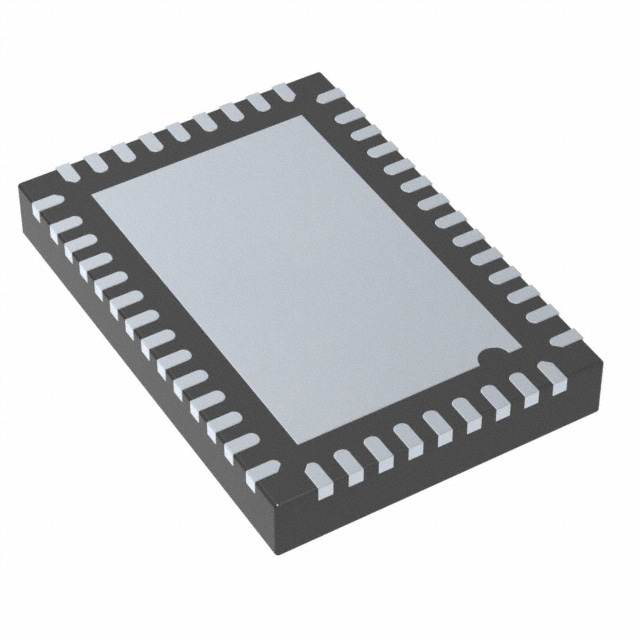
5. Package Specification
Package type:
Ex-VQFN46 (6.5 x 4.5 x 1.0 mm, 46 pins, 0.40 mm pitch)
5.1. Package Drawing and Dimensions
Figure 14.
MCDP6000 Ex-VQFN46 Package Outline Drawing (unit: mm)
MegaChips’ Proprietary Information –Confidential
Page 34 of 46
�MCDP6000
USB Type-C DP Alt-Mode Switching Retimer
6. Marking Field Template and Descriptors
Figure 15.
MCDP6000 Ex-VQFN46 Marking Template
M C
D
P
6
0
0
0
R
R
Y Y W W X X X X E S
Table 17.
Field
Field Descriptors
Description
Marking
DOT
Pin1 indicator
DOT
Line 2
Company logo
MegaChips
Line 3
Product Code + IC revision
MCDP6000RR
YYWW
Assembly Code (Work year + Work week)
“Variant”
xxxx
Identification number
“Variant”
ES
Fixed character only for ES, blank for MP
ES
MegaChips’ Proprietary Information –Confidential
Page 35 of 46
�MCDP6000
USB Type-C DP Alt-Mode Switching Retimer
7. Electrical Specifications
7.1. Absolute Maximum Ratings
Table 18.
Specifications
Absolute Maximum Ratings
Unit
Min
Typ
Max
Comments
1.2 V supply voltage
V
-0.3
-
1.5
1.8 V supply voltage
V
-0.3
-
2.5
RF signal input voltage tolerance
V
-0.3
-
1.4
USB SSTX, DP MLn
RF signal output voltage tolerance
V
-0.3
-
1.4
USB SSRX, TX1,
TX2
RF signal inout voltage tolerance
V
-0.3
-
1.4
RX1, RX2
ESD Rating
V
-1000
-
1000
HBM, RF pins
ESD Rating
V
-2000
-
2000
HBM, Other pins
Storage temperature
°C
-55
-
150
7.2. Device Operating Conditions
Table 19.
Device Operating Conditions
Specifications
Symbol
Unit
Min
Typ
Max
Ambient operating temperature
Ta
°C
0
-
70
1.2 V supply voltage
V12
V
1.14
1.20
1.26
1.8 V supply voltage
V18
V
1.65
1.80
1.95
Thermal resistance (Junction to Ambient)
θja
°C/W
-
-
36.6
Thermal resistance (Junction to Case)
θjc
°C/W
-
-
19.5
Junction-to-top characterization parameter
ψjt
°C/W
-
-
0.30
Junction-to-board characterization parameter
ψjb
°C/W
-
-
10.3
MegaChips’ Proprietary Information –Confidential
Page 36 of 46
�MCDP6000
USB Type-C DP Alt-Mode Switching Retimer
7.3. Electrical Characteristics
7.3.1. DC characteristics
Table 20.
Specifications
Symbol
DC Characteristics
Unit
Min
Typ
Max
Comments
Supply Current in 4-Lane active mode (USB 3.2 x1 Gen2 + DisplayPort HBR3 2 lane)
VDD 1.8 V
Id18
mA
10
13
VDD 1.2 V
Id12
mA
420
605
Supply Current in low power mode ({P_CONF1,P_CONF0}={0,0})
VDD 1.8 V
Is18
μA
70
VDD 1.2 V
Is12
μA
600
Input voltage
Vpad
V
3
Input high voltage
Vihod
V
2.4
Input low voltage
Vilod
V
Output low Current
Iol
mA
5.3
Positive Going Threshold Voltage
Vt+
V
Negative Going Threshold Voltage
Vt-
Hysteresis Voltage
Open drain IO (SCL, SDA)
3.3
3.6
0.35
8.7
10.7
At Vol = 0.4V
0.4 V18
0.7 V18
VOUT >= VOH(min)
V
0.3 V18
0.6 V18
VOUT


 工商网监
湘ICP备2023018690号
工商网监
湘ICP备2023018690号
