SIT3701AI-32-33C-54.000000T 数据手册
SiT3701
Smallest Voltage Controlled MEMS Oscillator (VCMO)
■ Features, Benefits and Applications
■ The world’s only VCMO with programmable pull range: ±60 PPM, ±120 PPM, ±240 PPM
■ Typical pull range linearity of 0.06%
■ 1-110 MHz frequency range
■ LVCMOS/LVTTL compatible output
■ Typical power consumption of 6.1 mA in active mode
■ Typical VCMO tuning voltage: 0 V to 1.85 V for all Vdds
■ Four industry-standard 4-pin packages: 2.5 x 2.0, 3.2 x 2.5, 5.0 x 3.2, 7.0 x 5.0 mm
■ All-silicon timing device with outstanding reliability of 2 FIT (10x improvement over
quartz-based devices), enhancing system MTBF
■ Ultra short lead time
■ Ideal for Set-top Box, DTV, DVD-R, instrumentation, low bandwidth analog PLL,
networking and communications
■ Specifications
Electrical Characteristics
Parameter
Output Frequency Range
Frequency Stability
Pull Range[1,2]
Symbol
Min.
Typ.
Max.
Unit
f
F_stab
1
-20
–
–
110
+20
MHz
PPM
-25
–
+25
PPM
-30
–
+30
PPM
-50
–
+50
PPM
PR
±60, ±120, ±240
Condition
Inclusive of: Initial stability, operating temperature, rated power,
supply voltage change, load change.
±20 PPM is available for extended commercial temperature
only.
PPM
Upper Control Voltage
VC_U
1.55
–
1.85
V
All Vdds. Voltage at which maximum deviation (+60, +120,
+240 PPM) is guaranteed.
Lower Control Voltage
VC_L
0
–
0.1
V
All Vdds. Voltage at which maximum deviation (-60, -120,
-240 PPM) is guaranteed.
Linearity
Frequency Change Polarity
Operating Temperature Range
Lin
–
T_use
–
0.06
Positive slope
–
–
1.8
2.5
2.8
3.3
6.7
6.1
–
–
1
1
–
0.25
+70
+85
1.89
2.75
3.08
3.63
7.5
6.7
55
60
2.0
2.5
–
%
–
°C
°C
V
V
V
V
mA
mA
%
%
ns
ns
%Vdd
Rise/Fall Time
Tr, Tf
Output Voltage High
VOH
-20
-40
1.71
2.25
2.52
2.97
–
–
45
40
–
–
90
Output Voltage Low
VOL
–
–
10
%Vdd
Ld
–
–
15
pF
Maximum frequency and supply voltage
Contact SiTime for higher output load
Start-up Time
RMS Period Jitter
T_osc
T_jitt
RMS Phase Jitter (random)
T_phj
–
–
–
–
–
–
–
0.6
10
6
4
–
ms
ps
ps
ps
–
0.8
–
ps
Time @ minimum supply voltage to be zero
f = 75 MHz, Vdd = 1.8 V
f = 75 MHz, Vdd = 2.5 V, 2.8 V or 3.3 V
f = 75 MHz, Integration bandwidth = 900 kHz to 7.5 MHz,
VDD = 2.5 V, 2.8 V, or 3.3 V
f = 75 MHz, Integration bandwidth = 900 kHz to 7.5 MHz,
VDD = 1.8 V
Supply Voltage
Vdd
Current Consumption
Idd
Duty Cycle
DC
Output Load
Extended Commercial
Industrial
No load condition, f = 20 MHz, Vdd = 2.5 V, 2.8 V or 3.3 V
No load condition, f = 20 MHz, Vdd = 1.8 V
All Vdds. f 75 MHz
Vdd = 2.5, 2.8 or 3.3 V, 20% - 80% Vdd level
Vdd = 1.8 V, 20% - 80% Vdd level
IOH = -4 mA (Vdd = 3.3 V)
IOH = -3 mA (Vdd = 2.8 V and Vdd = 2.5 V)
IOH = -2 mA (Vdd = 1.8 V)
IOL = 4 mA (Vdd = 3.3 V)
IOL = 3 mA (Vdd = 2.8 V and Vdd = 2.5 V)
IOL = 2 mA (Vdd = 1.8 V)
Notes:
1. Absolute Pull Range (APR) is defined as the guaranteed pull range over temperature and voltage.
2. APR = pull range (PR) - frequency stability (F_stab).
SiTime Corporation
Rev. 1.51
990 Almanor Avenue
Sunnyvale, CA 94085
(408) 328-4400
www.sitime.com
Revised August 9. 2010
�SiT3701
Smallest Voltage Controlled MEMS Oscillator (VCMO)
■ Specifications (Cont.)
Pin Description Tables
Pin #1 Functionality
VIN
Pin Map
0 - 1.85 V: produces voltage dependent frequency change
Pin
Connection
1
VIN
2
GND
3
CLK
4
VDD
Absolute Maximum Ratings
Attempted operation outside the absolute maximum ratings of the part may cause permanent damage to the part. Actual performance of the IC
is only guaranteed within the operational specifications, not at absolute maximum ratings.
Min.
Max.
Unit
Storage Temperature
Parameter
-65
150
°C
VDD
-0.5
4
V
Electrostatic Discharge
–
6000
V
Theta JA (with copper plane on VDD and GND)
–
75
°C/W
°C/W
Theta JC (with PCB traces of 0.010 inch to all pins)
–
24
Soldering Temperature (follow standard Pb free soldering guidelines)
–
260
°C
Number of Program Writes
–
1
NA
1,000+
–
years
Program Retention over -40 to 125°C, Process, VDD (0 to 3.65 V)
Environmental Compliance
Parameter
Condition/Test Method
Mechanical Shock
MIL-STD-883F, Method 2002; 50kG
Mechanical Vibration
MIL-STD-883F, Method 2007; 70G
Temperature Cycle
JESD22, Method A104
Solderability
MIL-STD-883F, Method 2003
Moisture Sensibility Level
MSL1 @ 260°C
Rev. 1.51
Page 2 of 4
www.sitime.com
�SiT3701
Smallest Voltage Controlled MEMS Oscillator (VCMO)
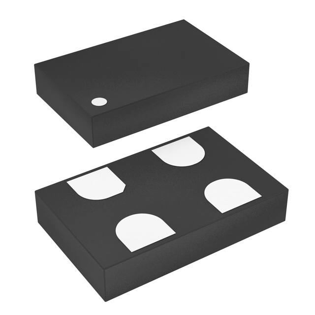
■ Dimensions and Land Patterns
Package Size – Dimensions (Unit: mm)[3]
Recommended Land Pattern (Unit: mm)[4]
2.5 x 2.0 x 0.75 mm
2.5 ± 0.10
#3
#4
0.5
1.5
1.1
#2
#2
#1
1.0
YXXXX
#1
1.9
1.00
#3
2.0 ± 0.10
#4
0.75 ± 0.05
0.75
1.1
3.2 x 2.5 x 0.75 mm
3.2 ± 0.15
2.1
#3
1.9
0.7
#2
#1
1.2
#2
0.9
0.75 ± 0.05
#1
#4
0.9
YXXXX
2.2
#3
2.5 ± 0.15
#4
1.4
5.0 x 3.2 x 0.75 mm
5.0 ± 0.15
#4
#2
#1
2.2
0.8
1.6
0.75 ± 0.05
#2
#3
1.1
YXXXX
#1
2.54
2.39
#3
3.2 ± 0.15
#4
1.15
1.5
7.0 x 5.0 x 0.90 mm
#3
5.08
#4
No Connect
[5]
#2
0.90 ± 0.10
#2
2.0
1.1
2.6
5.08
1.7
2.1
5.0 ± 0.15
YXXXX
#1
#3
3.81
7.0 ± 0.15
#4
#1
1.4
2.2
Notes:
3. Y denotes manufacturing origin and XXXX denotes manufacturing lot number. The value of “Y” will depend on the assembly location of the device.
4. A capacitor of value 0.1 µF between Vdd and GND is recommended.
5. The 7050 package with part number designation "-8" has NO center pad.
Rev. 1.51
Page 3 of 4
www.sitime.com
�SiT3701
Smallest Voltage Controlled MEMS Oscillator (VCMO)
■ Part No. Guide - How to Order
The Part No. Guide is for reference only. For real-time customization and exact part number, use the SiTime Part Number Generator.
SiT3701AC -14-18F - 105.12345T
Packaging
“T”: Tape & Reel, 3K reel
“Y”: Tape & Reel, 1K reel
Blank for Bulk
Part Family
“SiT3701”
Revision Letter
Frequency
1.00000 to 110.00000 MHz
“A” is the revision
Pull Range Options
“C” for ±60 PPM
“F” for ±120 PPM
Temperature Range
“C” Commercial, -20 to 70ºC
“I” Industrial, -40 to 85ºC
“I” for ±240 PPM
Output Driver Strength[6]
Supply Voltage
“–” Default
“18” for 1.8 V ±5%
“25” for 2.5 V ±10%
“28” for 2.8 V ±10%
“33” for 3.3 V ±10%
Package Size
“1” 2.5 x 2.0 mm
“2” 3.2 x 2.5 mm
“3” 5.0 x 3.2 mm
“4” 7.0 x 5.0 mm
“8” 7.0 x 5.0 mm [7]
Frequency Stability
“1” for ±20 PPM
“2” for ±25 PPM
“3” for ±50 PPM
“8” for ±30 PPM
Notes:
6. Contact SiTime for different drive strength options for driving higher loads or reducing EMI.
7. Without Center Pad.
Frequency Stability vs. Temperature Range Options
Frequency
Stability (PPM)
Temperature
Range
Supply Voltage
1.8 V
2.5 V
2.8 V
3.3 V
C (-20 to +70°C)
�
�
�
�
I (-40 to +85°C)
–
–
–
–
±25
C (-20 to +70°C)
I (-40 to +85°C)
�
�
�
�
±30
C (-20 to +70°C)
I (-40 to +85°C)
�
�
�
�
±50
C (-20 to +70°C)
I (-40 to +85°C)
�
�
�
�
±20
© SiTime Corporation 2010. The information contained herein is subject to change at any time without notice. SiTime assumes no responsibility or liability for any loss, damage or defect of a
Product which is caused in whole or in part by (i) use of any circuitry other than circuitry embodied in a SiTime product, (ii) misuse or abuse including static discharge, neglect or accident, (iii)
unauthorized modification or repairs which have been soldered or altered during assembly and are not capable of being tested by SiTime under its normal test conditions, or (iv) improper
installation, storage, handling, warehousing or transportation, or (v) being subjected to unusual physical, thermal, or electrical stress.
Disclaimer: SiTime makes no warranty of any kind, express or implied, with regard to this material, and specifically disclaims any and all express or implied warranties, either in fact or by
operation of law, statutory or otherwise, including the implied warranties of merchantability and fitness for use or a particular purpose, and any implied warranty arising from course of dealing or
usage of trade, as well as any common-law duties relating to accuracy or lack of negligence, with respect to this material, any sitime product and any product documentation. products sold by
sitme are not suitable or intended to be used in a life support application or component, to operate nuclear facilities, or in other mission critical applications where human life may be involved or
at stake. all sales are made conditioned upon compliance with the critical uses policy set forth below.
CRITICAL USE EXCLUSION POLICY
BUYER AGREES NOT TO USE SITIME'S PRODUCTS FOR ANY APPLICATION OR IN ANY COMPONENTS USED IN LIFE SUPPORT DEVICES OR TO OPERATE NUCLEAR FACILITIES
OR FOR USE IN OTHER MISSION-CRITICAL APPLICATIONS OR COMPONENTS WHERE HUMAN LIFE OR PROPERTY MAY BE AT STAKE.
SiTime owns all rights, title and interest to the intellectual property related to SiTime's products, including any software, firmware, copyright, patent, or trademark. The sale of SiTime products
does not convey or imply any license under patent or other rights. SiTime retains the copyright and trademark rights in all documents, catalogs and plans supplied pursuant to or ancillary to
the sale of products or services by SiTime. Unless otherwise agreed to in writing by SiTime, any reproduction, modification, translation, compilation, or representation of this material shall be
strictly prohibited.
Rev. 1.51
Page 4 of 4
Revised August 9. 2010
�


 工商网监
湘ICP备2023018690号
工商网监
湘ICP备2023018690号
