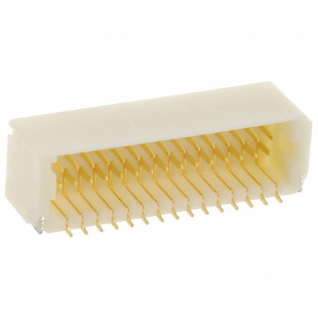
SHD CONNECTOR
Crimp
Emboss Tape
Disconnectable Crimp style connectors
1.0mm
(.039") pitch
Features ––––––––––––––––––––––––
• Ultra-compact, low profile design
The SHD connector is compact with a mounting height of
6.3mm (.248") for top entry type and 5.5mm (.217") for side
entry type, and a width of 5.0mm (.197") for top entry type and
5.1mm (.201") for side entry type.
• Reliable contact
The same contact can be used for the single-row SH
connectors.
• Anti-misinsertion feature
Ribs and grooves on the header and receptacle prevent
misinsertion and distortion during mating and unmating.
• Receptacles with protrusions
The receptacle has protrusions on both ends for an operator to
disengage the receptacle from the header without holding the
Ultra-compact, double-row design
wires.
• Header designed for vacuum pick and place robotics
Although this shrouded header has locking features for its
mating receptacle, there are no holes in the header shroud that
would adversely effect vacuum gripping equipment.
Since there is enough flat surface for secure vacuum gripping,
this miniature surface mount connector is versatile for designers
and economic for manufacturing.
Specifications –––––––––––––––––––
11
21
31
39
• Current rating: 1.0A AC, DC (AWG #28)
• Voltage rating: 50V AC, DC
• Temperature range: -25˚C to +85˚C
(including temperature rise in applying
electrical current)
• Contact resistance: Initial value/20m Ω max.
After environmental testing/40m Ω max.
• Insulation resistance:
100M Ω min.
• Withstanding voltage: 500V AC/minute
• Applicable wire: AWG #32 to #28
Insulation O.D./0.4 to 0.8mm (.016" to .031")
* Contact JST for details.
Standards ––––––––––––––––––––––
0
1
Recognized E60389
Certified LR20812
6
�SHD
CONNECTOR
Contact –––––––––––––––––––––––––––––––––––––––––––––––––––––––––––––––––
Model No.
3.9(.154)
1.6(.063)
1.55(.061)
SSH-003GA-P0.2
0.8(.031)
0.032 to 0.08
32 to 28
0.4 to 0.8(.016 to .031)
23,000
Material and Finish
1.35(.053)
2.0(.079)
0.5(.020) 0.8(.031)
Applicable wire
Q'ty /
Insulation O.D. mm(in.) reel
AWG#
mm2
Phosphor bronze, nickel-undercoated, selective gold-plated
Note: Contact JST for tin-plated contacts.
0.45(.018)
Housing –––––––––––––––––––––––––––––––––––––––––––––––––––––––––––––––––
Dimensions mm(in.)
Circuits
Model No.
20
SHDR-20V-S-B
9.0(.354)
11.2( .441)
13.0( .512)
4,000
30
SHDR-30V-S-B
14.0(.551)
16.2( .638)
18.0( .709)
4,000
40
SHDR-40V-S-B
19.0(.748)
21.2( .835)
23.0( .906)
2,000
50
SHDR-50V-S-B
24.0(.945)
26.2(1.031)
28.0(1.102)
2,000
A
C
4.9
(.193)
A
1.0(.039)
Circuit No.3
5.0
(.197)
No.1 mark
B
Q'ty / box
C
Material
PBT, UL94V-0, natural (white)
4.2
(.165)
B
Shrouded header –––––––––––––––––––––––––––––––––––––––––––––––––––––––––
Top entry type
Circuits
20
4.25(.167)
30
1.0
(.039)
40
50
1.5
(.059)
0.2(.008)
A
B
Circuit No.1 Circuit No.3
Circuits
0.7(.028)
5.0(.197)
20
30
Side entry type
40
Circuit No.3
Circuit No.1
50
Model No.
Top entry type
BM20B-SRDS-G-TF
BM30B-SRDS-G-TF
BM40B-SRDS-G-TF
BM50B-SRDS-G-TF
Model No.
Side entry type
SM20B-SRDS-G-TF
SM30B-SRDS-G-TF
SM40B-SRDS-G-TF
SM50B-SRDS-G-TF
H JST
0.2(.008)
0.7(.028)
B
0.6(.024)
4.25(.167)
Top entry type with a boss
1.0
(.039)
0.5(.020)dia.
0.2(.008)
Circuit No.1
A
B
Circuit No.3
0.85(.033)
9.0(.354) 12.3( .484)
1,500
14.0(.551) 17.3( .681)
1,500
19.0(.748) 22.3( .878)
1,500
24.0(.945) 27.3(1.075)
1,500
Dimensions mm(in.)
A
B
Q'ty / reel
9.0(.354) 13.1(.516)
1,250
14.0(.551) 18.1(.713)
1,250
19.0(.748) 23.1(.909)
1,250
24.0(.945) 28.1(1.106)
1,250
Header contact: Phosphor bronze, nickel-undercoated, gold-plated
Wafer: Glass-filled polyamide, UL94V-0, natural (ivory)
Solder tab: Brass, copper-undercoated, tin/lead-plated
1.5(.059)
5.1(.201)
A
Q'ty / reel
Material and Finish
5.5(.216)
1.0
(.039)
Dimensions mm(in.)
A
B
1.9
(.075)
1.5
(.059)
5.0(.197)
Note: 1. The products listed above are supplied on embossed-tape.
2. Contact JST for the headers with tin-plated pins.
3. Contact JST for the top entry type headers with suction cap.
Dimensions mm(in.)
A
B
Q'ty / reel
BM20B-SRDS-A-G-TF
9.0(.354) 12.3( .484)
1,250
BM30B-SRDS-A-G-TF
14.0(.551) 17.3( .681)
1,250
40
BM40B-SRDS-A-G-TF
19.0(.748) 22.3( .878)
1,250
50
BM50B-SRDS-A-G-TF
24.0(.945) 27.3(1.075)
1,250
Circuits
Model No.
20
30
Material and Finish
0.7(.028)
Header contact: Phosphor bronze, nickel-undercoated, gold-plated
Wafer: Glass-filled polyamide, UL94V-0, natural (ivory)
Solder tab: Brass, copper-undercoated, tin/lead-plated
Note: 1. The products listed above are supplied on embossed-tape.
2. Contact JST for the headers with tin-plated pins.
7
�SHD
CONNECTOR
Taping specifications ––––––––––––––––––––––––––––––––––––––––––––––––––––––
Carrier tape
380.0±2.0(14.961±.079)
Feeding direction
W1+2.5
-1.0
(W1+.098
-.039 )
Lead tape
(Unloaded area)
20 vacancies min.
Connector
loaded area
400(15.748)min.
2±0.5(.079±.02)
4.0±0.1 2.0±0.1 1.55±0.05dia.
Feeding direction (.157±.004) (.079±.004) (.061±.002)
1.75±0.1
(.069±.004)
(.069±.004)
(20 circuits)
5.05
(.199)
0.8
(.031)
0.3±0.05
(.012±.002)
Carrier tape
F±0.1(.004)
W±0.3(.012)
F±0.1(.004)
1.75±0.1
4.0±0.1 2.0±0.1 1.55±0.05dia.
Feeding direction (.157±.004) (.079±.004) (.061±.002)
Tail tape
(Unloaded area)
40.0(1.575)min.
W±0.3(.012)
(30,40,50 circuits)
Top entry type
S±0.1(.004)
[13.0(.512)dia.]
Cover tape leader area
Feeding direction
Cover tape
12.0±0.1
(.472±.004)
(30,40,50 circuits)
1.75±0.1
(.069±.004)
5.75
(.226)
4.0±0.1 2.0±0.1 1.55±0.05
Feeding direction (.157±.004) (.079±.004) (.061±.002)dia.
W
F±0.1(.004)
S±0.1(.004)
1.75±0.1
(.069±.004)
(20 circuits)
4.0±0.1
2.0±0.1 1.55±0.05
Feeding direction (.157±.004) (.079±.004) (.061±.002)dia.
12.0±0.1
(.472±.004)
Circuits
Reel dimensions mm(in.)
W1
W
Top entry type Side entry type Top entry type Side entry type Top entry type
Q'ty / reel
Side entry type Top entry type Side entry type
Top entry type
Side entry type
24.0( .945)
25.5(1.004)
25.5(1.004)
1,500
1,250
32.0(1.260)
32.0(1.260)
33.5(1.319)
33.5(1.319)
1,500
1,250
40.4(1.591)
44.0(1.732)
44.0(1.732)
45.5(1.791)
45.5(1.791)
1,500
1,250
40.4(1.591)
44.0(1.732)
44.0(1.732)
45.5(1.791)
45.5(1.791)
1,500
1,250
20
11.5(.453)
11.5(.453)
–
–
24.0( .945)
30
14.2(.559)
14.2(.559)
28.4(1.118)
28.4(1.118)
40
20.2(.795)
20.2(.795)
40.4(1.591)
50
20.2(.795)
20.2(.795)
40.4(1.591)
Note: 1. Specifications conform to JIS C 0806. The tape width, connector loading recess square dimensions,
etc.are determined by the number of circuits and external shape of the connector to be loaded.
Note: 2. Specifications are subject to change without prior notice.
8
Carrier tape
Cover tape
Dimensions mm(in.)
S
F
0.3±0.05
(.012±.002)
F±0.1(.004)
W±0.3(.012)
Side entry type
�SHD
CONNECTOR
PC board layout (viewed from component side) and Assembly layout ––––––––––––––––––
Side entry type
Top entry type
with a boss
5.4(.213)
Circuit No.1
0.7
Header outline (.028)
Circuit No.1
0.7
(.028)
1.0±0.1 0.6
(.039±.004) (.024)
0.9±0.1
(.035±.004)
0.85±0.1
(.033±.004)
0.5
(.020)
5.5
(.217)
4.1(.161)
0.85±0.1
(.033±.004)
1.9±0.1
(.075±.004)
0.9 1.8±0.1
(.035)(.071±.004)
1.5
(.059)
5.0(.197)
0.6
1.0±0.1
(.039±.004) (.024)
7.1
(.280)
1.6
(.063)
Header outline
1.6
(.063)
0.85±0.1
(.033±.004)
6.3(.248)
0.9±0.1
(.035±.004)
0.5
(.020)
1.8±0.1
(.071±.004)
4.0(.157)
7.2(.283)
1.0±0.1
0.6
(.039±.004) (.024)
0.7
(.028)
1.5(.059)
5.1(.201)
0.7
(.028)
0.55+0.05
0
(.022+0.05
0 )dia.
1.8±0.1
(.071±.004)
4.0(.157)
7.2(.283)
Top entry type
Header outline
Circuit No.1
0.85±0.1
1.25±0.1
(.049±.004) (.033±.004)
Note: 1. Tolerances are non-Cumulative: ±0.05mm( ±.002") for all centers.
Note: 2. Hole dimensions differ according to the kind of PC board and piercing method.
Note: The dimensions above should serve as a guide line. Contact JST for details.
Applicator for the semi-automatic press AP-K2N –––––––––––––––––––––––––––––––
Contact
SSH-003GA-P0.2
Crimp applicator MKS-L-10-3
with safety cover
without safety cover
APLMK SSH/L003-02
APLNC SSH/L003-02
Compact crimp applicator MKS-LS
with safety cover
without safety cover
–
–
Strip-crimp applicator MKS-SC
with safety cover
APLSC SSH003-02
9
�


 工商网监
湘ICP备2023018690号
工商网监
湘ICP备2023018690号
