Additional Resources:
Product Page
date
09/05/2017
page
1 of 4
SERIES: MD-SMK │ DESCRIPTION: MINI DIN CONNECTOR
ED
FEATURES
U
• PCB mount
• right angle
• side shielded with kinked pins
N
RoHS
TI
PART NUMBER KEY
N
MD - XX SMK
Pin Options
30 = 3 pins
40 = 4 pins
50 = 5 pins
60 = 6 pins
70 = 7 pins
80 = 8 pins
IS
C
O
Base Number
SPECIFICATIONS
parameter
conditions/description
min
rated input voltage
rated input current
typ
at 100 Vac
at 12 Vdc
contact resistance
insulation resistance
at 250 Vdc
voltage withstand
for 1 minute
max
100
12
Vac
Vdc
1
2
A
A
30
mΩ
250
Vac
50
MΩ
1
4.5
kg
withdrawal force
0.8
3
kg
operating temperature
-40
D
insertion force
units
life
85
1,000
flammability rating
UL94V-0
RoHS
2011/65/EU
cui.com
°C
cycles
�Additional Resources:
Product Page
CUI Inc │ SERIES: MD-SMK │ DESCRIPTION: MINI DIN CONNECTOR
date 09/05/2017 │ page 2 of 4
MECHANICAL DRAWINGS
units: mm[inches]
TOLERANCE: ±0.2mm
12.8 0.504
phosphor bronze
silver
shield plate
steel
tin
housing
PBT
1.8 0.071
7 6
4
2
3
1
N
6.5 0.256
0.30 0.012
(TYP)
2.0 0.079
(2 PLCS)
3.5 0.138
(TYP)
13.5 0.531
tin
U
8
5
PLATING
brass
contact terminals (1~8)
12.9 0.508
14.0 0.551
MATERIAL
ED
earth terminal
0.7 0.028
(TYP)
TI
5.5 0.217
(2 PLCS)
8.5 0.335
(4 PLCS)
IS
C
O
N
11.0 0.433
(4 PLCS)
MD-30SMK
D
11.0 0.433
0.9±0.1
0.035
(3 PLCS)
8.5 0.335
(2 PLCS)
1
4
MD-50SMK
5
3
4
2
3
1
13.5 0.531
13.5 0.531
5.5 0.217
(2 PLCS)
4.7 0.185
8.5 0.335
(2 PLCS)
11.0 0.433
(2 PLCS)
0.7X2.2
(3 PLCS)
0.9 0.035
6.8 0.268
1.0 0.039
(4 PLCS) 0.1
1
2
3
10.0 0.394
2
13.5 0.531
4.7 0.185
1.0 0.039
(2 PLCS) MAX
SOLDER WELDS
MD-40SMK
1
5.5 0.217
(2 PLCS)
9.1 0.358
(2 PLCS)
5.0 0.197
3
2
1.5 0.059
(2 PLCS)
0.9±0.1
0.035
(4 PLCS)
1
2
3
4
6.8 0.268
PCB LAYOUT
TOP VIEW
PCB LAYOUT
TOP VIEW
cui.com
5.5 0.217
(2 PLCS)
4.7 0.185
8.5 0.335
(3 PLCS)
11.0 0.433
(2 PLCS)
2
0.7X2.2
(3 PLCS)
1
4
0.9±0.1
0.035
(5 PLCS)
3
0.7X2.2
(3 PLCS)
5
1.3 0.051
6.8 0.268
PCB LAYOUT
TOP VIEW
�Additional Resources:
Product Page
CUI Inc │ SERIES: MD-SMK │ DESCRIPTION: MINI DIN CONNECTOR
date 09/05/2017 │ page 3 of 4
MECHANICAL DRAWINGS (CONTINUED)
7
5
2
4.7 0.185
8.5 0.335
(4 PLCS)
2
5
1
6
4.7 0.185
8.5 0.335
(4 PLCS)
11.0 0.433
(3 PLCS)
3
0.7X2.2
(3 PLCS)
0.9±0.1 0.035
(6 PLCS)
5
0.9±0.1 0.035
(7 PLCS)
2.6 0.102
2.6 0.102
1
2
6
4
5.5 0.217
(2 PLCS)
0.7X2.2
(3 PLCS)
7
0.9 0.035
PCB LAYOUT
TOP VIEW
TI
N
O
IS
C
D
cui.com
4.7 0.185
8.5 0.335
(4 PLCS)
11.0 0.433
(4 PLCS)
6.8 0.268
6.8 0.268
PCB LAYOUT
TOP VIEW
3
1
13.5 0.531
5.5 0.217
(2 PLCS)
4
4
2
3
1
6
4
2
7
5
0.7X2.2
(3 PLCS)
8
0.9±0.1 0.035
(8 PLCS)
2.6 0.102
N
11.0 0.433
(2 PLCS)
7 6
5
13.5 0.531
5.5 0.217
(2 PLCS)
1
8
3
2
1
13.5 0.531
3
6 5
4
3
4
MD-80SMK
U
6
MD-70SMK
ED
MD-60SMK
6.8 0.268
PCB LAYOUT
TOP VIEW
0.9 0.035
�Additional Resources:
Product Page
CUI Inc │ SERIES: MD-SMK │ DESCRIPTION: MINI DIN CONNECTOR
date 09/05/2017 │ page 4 of 4
REVISION HISTORY
description
date
02/23/2006
1.0
initial release
1.01
new template applied
1.02
updated datasheet
ED
rev.
02/22/2012
09/05/2017
D
IS
C
O
N
TI
N
U
The revision history provided is for informational purposes only and is believed to be accurate.
Headquarters
20050 SW 112th Ave.
Tualatin, OR 97062
800.275.4899
Fax 503.612.2383
cui.com
techsupport@cui.com
CUI offers a one (1) year limited warranty. Complete warranty information is listed on our website.
CUI reserves the right to make changes to the product at any time without notice. Information provided by CUI is believed to be accurate and reliable. However, no responsibility is
assumed by CUI for its use, nor for any infringements of patents or other rights of third parties which may result from its use.
CUI products are not authorized or warranted for use as critical components in equipment that requires an extremely high level of reliability. A critical
component is any component of a life support device or system whose failure to perform can be reasonably expected to cause the failure of the life support device or system, or to
affect its safety or effectiveness.
�
很抱歉,暂时无法提供与“MD-60SMK”相匹配的价格&库存,您可以联系我们找货
免费人工找货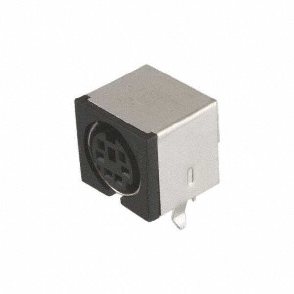


 工商网监
湘ICP备2023018690号
工商网监
湘ICP备2023018690号
