Metal Shell Circular Connectors
HS Series
Introduction
·�The HS series is generally called “metal connector”,
and is the most widely used standard multi-pin
circular connector.
·�Being sturdy and simple in construction, the HS
connectors are stable mechanically and electrically
and are employed by NTT and set manufacturers
as standard parts.
Material
Part
Material
Finish
Shell
Copper compound metal
Nickel plated
Insulator
Synthetic resin
-----------------
Male contacts
Brass
Female contacts
Brass or phosphor bronze
Nickel plated
Ordering information
HS 21 P A - 2 A
q
w
e
r
t
y
qModel name: HS stands for HIROSE STANDARD.
wShell size: �The shell size is expressed as the outside diameter of the plug fitting section (insulator)
with seven types: 12, 14, 16, 21, 25, 28 and 35.
eShell type: The shell is classified into the following types.
P : Plug
R : Receptacle
J : Jack
RC : Receptacle cap
rShell model change mark: Each time the shell undergoes a model change, it is marked as A, B or C.
tNumber of contacts
y�Contact arrangement change mark: When the contact fitting section or contact arrangement undergoes a change,
it is marked as A, B, C....after the number of contacts.
2014.12w
1
�HS Series●Metal Shell Circular Connectors
Plug
Caulking
(Representative example)
HS21P−2(71)
HRS No.
101-0002-0 71
2
ØA
ØB
ØC
D
L
HS12P-2(71)
Part No.
12
18
7
M15.5×1
38
13.5
21.5
8.5
M19×1
43
101-0013-7 71
HS14P-2(71)
101-0030-6 71
HS16P-2(71)
101-0031-9 71
HS16P-3(71)
101-0034-7 71
HS16P-4(71)
101-0275-3 71
HS16P-5(71)
101-0053-1 71
HS21P-2(71)
101-0060-7 71
HS21P-3(71)
101-0066-3 71
HS21P-4(71)
101-0669-1 71
HS21P-5(71)
101-0074-1 71
HS21P-6(71)
101-0075-4 71
HS21P-7(71)
101-0076-7 71
HS21P-8(71)
101-0369-5 71
HS21P-10(71)
101-0115-7 71
HS25P-2(71)
101-0117-2 71
HS25P-3(71)
101-0122-2 71
HS25P-6(71)
101-0128-9 71
HS25P-8(71)
101-0129-1 71
HS25P-10(71)
101-0154-9 71
HS28P-4(71)
101-0158-0 71
HS28P-8(71)
101-0187-8 71
HS35PB-16(71)
101-0189-3 71
HS35PB-20(71)
15.5
21
28
M25×1
50
10
49
25
32
28
38
35
46
M29×1
54.5
16
M34×1
64.5
19
M41×1
71.5
�HS Series●Metal Shell Circular Connectors
Receptacle
3-ØE
HS21R−2(71)
HRS No.
Part No.
101-0007-4 71
HS12R-2(71)
101-0016-5 71
HS14R-2(71)
101-0040-0 71
HS16R-2(71)
101-0041-2 71
HS16R-3(71)
101-0042-5 71
HS16R-4(71)
101-0448-0 71
HS16R-5(71)
101-0084-5 71
HS21R-2(71)
101-0089-9 71
HS21R-3(71)
101-0091-0 71
HS21R-4(71)
101-0093-6 71
HS21R-5(71)
101-0095-1 71
HS21R-6(71)
101-0096-4 71
HS21R-7(71)
101-0097-7 71
HS21R-8(71)
101-0370-4 71
HS21R-10(71)
101-0130-0 71
HS25R-2(71)
101-0131-3 71
HS25R-3(71)
101-0135-4 71
HS25R-6(71)
101-0137-0 71
HS25R-8(71)
101-0138-2 71
HS25R-10(71)
101-0163-0 71
HS28R-4(71)
101-0166-8 71
HS28R-8(71)
(Representative example)
ØB
ØC
D
ØE
ØF
L
23
19
M15.5×1
2.1*
14
22.5
M
N
1.5
16.5
32
25.5
M19×1
41
33
M25×1
19
25
23
26.5
16
19.5
3.2
2
24.5
46
37
M29×1
29
17.5
19.5
26.5
51
43
M34×1
32
19
Note: 1.6Ø flat head screw is recommended for mounting.
3
�HS Series●Metal Shell Circular Connectors
Receptacle
HS35RA−16(71)
HRS No.
(Representative example)
Part No.
101-0200-4 71
HS35RA-16(71)
101-0201-7 71
HS35RA-20(71)
B
C
D
ØE
ØF
L
M
N
43
35
M41×1
3.2
40
31
21.5
2.5
Jack
(Representative example)
HS21J-2(71)
HRS No.
Part No.
101-0010-9 71
HS12J-2(71)
101-0047-9 71
HS16J-2(71)
101-0048-1 71
HS16J-3(71)
101-0049-4 71
HS16J-4(71)
101-0416-3 71
HS16J-5(71)
101-0104-0 71
HS21J-2(71)
101-0107-9 71
HS21J-5(71)
ØB
ØC
D
L
18
7
M15.5×1
44.5
21.5
8.5
M19×1
50
28
10
M25×1
57
Cap for Receptacle
(Representative example)
HS21RC(72)
HRS No.
Part No.
ØA
B
101-0011-1 72
HS12RC(72)
18
M15.5×1
101-0027-1 72
HS14RC(72) 21.5
M19×1
101-0109-4 72
HS21RC(72)
M25×1
28
C
7
HRS No.
Part No.
ØA
B
101-0148-6 72
HS25RC(72)
32
M29×1
101-0174-6 72
HS28RC(72)
38
M34×1
101-0207-3 72
HS35RC(72)
46
M41×1
C
7
9
Note: Part No. HS14RC is possible to use as cap of size 16.
4
�HS Series●Metal Shell Circular Connectors
Terminal Arrangement
Shell size
Shell size
12
14
No. of contacts
2
No. of contacts
Withstanding voltage AC 1000V a minute
Current rating
2
Withstanding voltage AC 1000V a minute
7A
Current rating
7A
Insulation resistance
1000 Mø MIN.
Insulation resistance
1000 Mø MIN.
Contact resistance
5 mø MAX.
Contact resistance
5 mø MAX.
Solder cup dia.
Ø1.5
Solder cup dia.
Ø1.5
Shell size
16
No. of contacts
2
3
4
5
AC 1000V a minute
Withstanding voltage
7A
Current rating
Insulation resistance
1000 Mø MIN.
Contact resistance
5 mø MAX.
Ø1.8
Solder cup dia.
Ø1.5
Shell size
21
No. of contacts
2
3
4
AC 1000V a minute
Withstanding voltage
10A
Current rating
6
7A
Insulation resistance
1000 Mø MIN.
Contact resistance
5 mø MAX.
Ø2.0
Solder cup dia.
5
AC 500V a minute AC 1000V a minute
Ø1.5
Shell size
21
No. of contacts
7
Current rating
7A
10
4A
3A
1000 Mø MIN.
Insulation resistance
5 mø MAX.
Contact resistance
Solder cup dia.
8
AC 1000V a minute
Withstanding voltage
Ø1.5
Ø1.2
Ø1.5
5
�HS Series●Metal Shell Circular Connectors
Shell size
25
2
No. of contacts
3
6
AC 1000V a minute
Withstanding voltage
10A
Current rating
1000 Mø MIN.
Insulation resistance
5 mø MAX.
Contact resistance
Ø2.0
Solder cup dia.
Shell size
Shell size
25
28
10
No. of contacts
Withstanding voltage
4A
5 mø MAX.
Ø1.2
Solder cup dia.
Withstanding voltage
7A
10A
1000 Mø MIN.
Insulation resistance
5 mø MAX.
Contact resistance
Solder cup dia.
8
AC 1000V a minute
Current rating
1000 Mø MIN.
Contact resistance
4
No. of contacts
AC 1000V a minute
Current rating
Insulation resistance
8
Ø1.8(Receptacle: Ø1.5)
Ø2.0
Shell size
35
16
No. of contacts
20
AC 1000V a minute
Withstanding voltage
4A
Current rating
1000 Mø MIN.
Insulation resistance
5 mø MAX.
Contact resistance
Ø1.2
Solder cup dia.
Note:
1. Contact arrangements are shown at the fitting section of Plug.
2. Insulation resistance is measured at DC 500V.
3. Contact resistance is measured at DC 1A.
4. �Withstanding voltage is shown as test voltage, so that the preferable value for daily operation is about one-third of each figure.
®
6
2-6-3,Nakagawa Chuoh,Tsuzuki-Ku,Yokohama-Shi 224-8540,JAPAN
TEL: +81-45-620-3526 Fax: +81-45-591-3726
http://www.hirose.com
http://www.hirose-connectors.com
The characteristics and the specifications contained herein are for reference purpose. Please refer to the latest customer drawings prior to use.
The contents of this catalog are current as of date of 12/2014. Contents are subject to change without notice for the purpose of improvements.
�
很抱歉,暂时无法提供与“HS25P-5(71)”相匹配的价格&库存,您可以联系我们找货
免费人工找货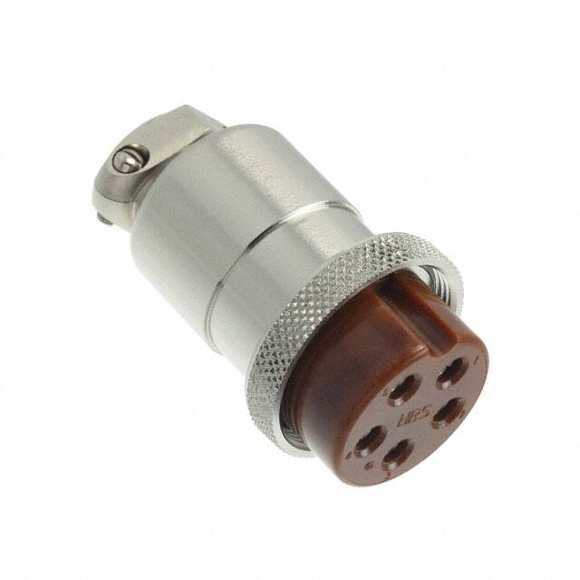


 工商网监
湘ICP备2023018690号
工商网监
湘ICP备2023018690号
