MOD Series
M Series
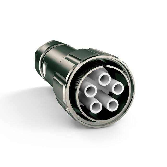
MC Series MCS Series
VP Series
100 Series
S Series
Series
Operating voltage from 10 kVDC to 15 kVDC
Operating current up to 13 A
2 - 5 HV contacts
For cable sizes AWG 26-14
�General characteristics and
technical data Series MC
Series
Housing
Locking system
threaded coupling
Mounting type (panel mount connector)
4-hole flange
Housing material basis / adapter
brass (CuZn)
Surface plating
nickel (Ni)
Protection class (mated connector)
IP60 (IP65 on request)
Operating temperature
-30°C to +80°C
Contacts 1.6 mm
Termination method
solder / crimp
Rated current
13 A
Contact resistance
≤ 5 mΩ
Contact diameter
1.6 mm [.063"]
Wire size (AWG / cross section)
AWG 26 - 14 (0.14 mm² - 2.5 mm²)
Contact material
brass (CuZn)
Contact plating
silver (Ag) / gold (Au)
Mating cycles
≥ 1,000
Number of contacts
2, 3, 4, 5
Insulation material
PTFE / POM
CTI value
600
Flammability class PTFE
UL94 V-0
Flammability class POM
UL94 HB
Operating temperature PTFE
-50°C to +200°C
Operating temperature POM
-30°C to +120°C
Insulating material group PTFE / POM
I (DIN IEC 60664)
MC Series
Insulation inserts
Suitable cable dimensions (single wire)
max. Ø 4.0 mm [.165"]
AWG 26 - 14
© GES Electronic & Service GmbH
www.ges-electronic.de
85
�Type MC507 5-pole 10 kVDC
Series
Plug, cable mount / Receptacle, panel mount / Receptacle, coupling, cable mount
Electrical values
Characteristics
Operating voltage (DC)
10 kV
Number of pins
5
Test voltage (DC)
15 kV
Insulation material
POM
Rated current
13 A
Type / Version / Part number
Picture / Drawing
KS-MC507
Plug, cable mount with integrated cable gland
Part no.
5005030A
5005030B
5005030C
5005030D
5005030E
Clamping range
6.5 - 8 mm [.256" - .315"]
8 - 9.5 mm [.315" - .374"]
9.5 - 11 mm [.374" - .433"]
11 - 12.5 mm [.433" - .492"]
12.5 - 14 mm [.492" - .551"]
front view
KS-MC507
Plug, cable mount with adapter
M20/M25 for external cable
gland
Part no.
5005030M
5005030N
Connecting thread
M20 x 1.5
M25 x 1.5
MC Series
front view
GB-MC507
Receptacle, panel mount
Part no. 5005010R
front view
KBI-MC507
Receptacle, coupling, cable
mount with integrated cable
gland
Part no.
5005042A
5005042B
5005042C
5005042D
5005042E
Clamping range
6.5 - 8 mm [.256" - .315"]
8 - 9.5 mm [.315" - .374"]
9.5 - 11 mm [.374" - .433"]
11 - 12.5 mm [.433" - .492"]
12.5 - 14 mm [.492" - .551"]
front view
KBI-MC507
Receptacle, coupling, cable
mount with adapter M20/M25
for external cable gland
Part no.
5005042M
5005042N
Connecting thread
M20 x 1.5
M25 x 1.5
front view
drawing - dimensions in mm [inch]
Contacts, cable glands and accessories on pages 96-98
Mounting instructions on pages 99-110
92
© GES Electronic & Service GmbH
www.ges-electronic.de
�Type MC507 5-pole 10 kVDC
Series
Receptacle, cable mount / Plug, panel mount
Type / Version / Part number
Picture / Drawing
KB-MC507
Receptacle, cable mount with
integrated cable gland
Part no.
5005040A
5005040B
5005040C
5005040D
5005040E
Clamping range
6.5 - 8 mm [.256" - .315"]
8 - 9.5 mm [.315" - .374"]
9.5 - 11 mm [.374" - .433"]
11 - 12.5 mm [.433" - .492"]
12.5 - 14 mm [.492" - .551"]
front view
KB-MC507
Receptacle, cable mount with
adapter M20/M25 for external
cable gland
Part no.
5005040M
5005040N
Connecting thread
M20 x 1.5
M25 x 1.5
MC Series
front view
GS-MC507
Plug, panel mount
Part no. 5005020R
front view
drawing - dimensions in mm [inch]
Contacts, cable glands and accessories on pages 96-98
Mounting instructions on pages 99-110
© GES Electronic & Service GmbH
www.ges-electronic.de
93
�Assembly Instructions
Series MC - type 207 - 507
receptacle, panel mount
Series
6.
1.
Remove dielectric insulation of single wires
(L3 = 5 - 8 mm [.197" - .315"]).
Part as supplied
Shrinking tubes (1), female contacts (2),
connector housing (3)
7.
2.
Crimp or solder one female contact (2) on
each conductor.
! F
� or soldering: Tin-solder must not remain
on contact surface!
Panel cut out
L1 mm
[inch]
D1 mm
[inch]
D2 mm
[inch]
GB 207 / 307 / 407
26.90
[1.059"]
3.00
[.118"]
26.00
[1.024"]
GB 507
29.30
[1.154"]
3.00
[.118"]
29.00
[1.142"]
8.
Put shrinking tubes (1) on insulation tubes
on rear side of connector housing (3).
3.
9.
MC Series
Type
Carefully remove cable jacket.
Type
L2 mm [inch]
GB 207 / 307 / 407 / 507
!
min. 45 [1.772"]
Slide contacts (2) completely into insulation
tubes until contacts snap into place.
... Pull gently to check that contacts are
correctly located and remain in position.
D
� o not damage metal shield braid
4.
10.
Fold back shield braid.
5.
Shrink tubes - shrinking temperature 110°C.
11.
Remove any filling elements from cable.
© GES Electronic & Service GmbH
Assembly finished.
www.ges-electronic.de
99
�Assembly Instructions
Series MC - type 207 - 507
plug, panel mount
1.
Series
5.
Remove any filling elements from cable.
Part as supplied.
Male contacts (1), connector housing (2)
6.
2.
Remove dielectric insulation of single wires
(L3 = 5 - 8 mm [.197" - .315"]).
MC Series
Panel cut out
Type
L1 mm
[inch]
D1 mm
[inch]
D2 mm
[inch]
GS 207 / 307 / 407
26.90
[1.059"]
3.00
[.118"]
26.00
[1.024"]
GS 507
29.30
[1.154"]
3.00
[.118"]
29.00
[1.142"]
7.
Crimp or solder one male contact (1) on
each conductor.
� or soldering: Tin-solder must not remain
! F
on contact surface!
3.
8.
Carefully remove cable jacket.
Type
L2 mm [inch]
GS 207 / 307 / 407 / 507
!
min. 45 [1.772"]
D
� o not damage metal shield braid
4.
Slide contacts (1) completely into connector
shell (2) until contacts snap into place.
... �Pull gently to check that contacts are correctly
located and remain in position.
9.
Fold back shield braid.
Assembly finished.
100
© GES Electronic & Service GmbH
www.ges-electronic.de
�Assembly Instructions
Series MC - type 207 - 507
plug, cable mount
Series
1.
5.
Fix shield braid with tape.
Part as supplied
Male contacts (1), cap (2), sealing insert (3),
screw joint (4), basis (5), threaded pin (6),
insulation insert (7).
2.
6.
Remove any filling elements from cable.
3.
MC Series
Place cap (2), sealing insert (3), screw joint
(4) and basis (5) onto cable.
7.
Remove dielectric insulation
(L3 = 5 - 8 mm [.197" - .315"]).
Remove cable jacket.
Type
L1 mm [inch]
L2 mm [inch]
KS 207 / 307 / 407 / 507
50 [1.968"]
35 [1.377“]
!
Do not damage metal shield braid
8.
4.
Fold back shield braid over jacket.
© GES Electronic & Service GmbH
Crimp or solder female contacts (1) on conductor.
� or soldering: Tin-solder must not remain on
! F
contact surface.
www.ges-electronic.de
101
�Assembly Instructions
Series MC - type 207 - 507
plug, cable mount
Series
13.
9.
Slide contacts completely into insulation insert (7)
until contacts snap into place.
... Pull gently to check that contacts are correctly
located and remain in position.
Insert sealing (3) completely and screw
cap (2) onto basis (5).
Cable gland type
10.
KS 207 / 307 / 407
23
26
26
26
MC Series
14.
11.
Assembly finished.
Secure insulation insert (7) with threaded
pin (6), then screw joint (4) onto basis (5).
12.
Widen shield braid.
102
© GES Electronic & Service GmbH
SW 2
KS 507
Tightening torque is 7 Nm
Remove tape and place basis (5)
onto insulation insert (7)
SW 1
www.ges-electronic.de
�Assembly Instructions
Series MC - type 207 - 507
receptacle cable mount & coupling
Series
1.
5.
Fix shield braid with tape.
Part as supplied.
Female contacts (1), cap (2), sealing insert (3),
screw joint (4), basis (5), threaded pin (6),
insulation insert (7).
2.
6.
Remove any filling elements from cable.
3.
MC Series
Place cap (2), sealing insert (3), screw
joint (4) and basis (5) onto cable
7.
Remove dielectric insulation
(L3 = 5 - 8 mm [.197" - .315"]).
Remove cable jacket.
Type
L1 mm [inch]
L2 mm [inch]
KS 207 / 307 / 407 / 507
50 [1.968"]
35 [1.377“]
!
D
� o not damage metal shield braid.
8.
4.
Fold back shield braid over jacket.
© GES Electronic & Service GmbH
Crimp or solder female contacts (1) on conductor.
� or soldering: Tin-solder must not remain on
! F
contact surface.
www.ges-electronic.de
103
�Assembly Instructions
Series MC - type 207 - 507
receptacle cable mount & coupling
13.
9.
Slide female contacts completely into insulation
insert until contacts snap into place.
... P
� ull gently to check that contacts are correctly
located and remain in position.
Insert sealing (3) completely and screw
cap (2) onto basis (5).
Cable gland type
10.
MC Series
Remove tape and place basis (5)
onto insulation insert (7)
23
26
26
26
Assembly finished.
Secure insulation insert (7) with threaded
pin (6), then screw joint (4) onto basis (5).
12.
Widen shield braid.
© GES Electronic & Service GmbH
SW 2
KB 207 / 307 / 407
14.
11.
SW 1
KB 507
Tightening torque is 7 Nm
104
Series
www.ges-electronic.de
�


 工商网监
湘ICP备2023018690号
工商网监
湘ICP备2023018690号
