Technical Data 4127
Effective October 2017
Supersedes March 2007
SD3112
Low profile metalized shielded drum core power inductors
Applications
•
•
Mobile phones
Digital cameras
Media players
Small LCD displays
LED driver and LED flash circuits
Hard disk drives
LCD Backlighting
l
i
t
n
u
r 14
o
6 31 nt.
1
0 SD me
2
,
1
3 view lace
p
y
l
e
e
r
u e
r
J
e
e eas at
v
i
t Pl ern
c
t
fe d.
l
f
a
E te
n
,
a
e
d
l
e ep as
u
)
n sd
i
8
t
2
n yi
1
o
sc tor t (4
i
D en ee
inv ta sh
da
•
•
•
•
•
SMD Device
Environmental data
•
Product features
•
•
•
•
•
3.1 mm x 3.1 mm x 1.2 mm shielded drum
core
Ferrite core material
Inductance range from 1.0 uH to 220 uH
Current range from 1.65 A to 0.113 A
Frequency range up to 4 MHz
•
•
Storage temperature range (component):
-40 °C to +125 °C
Operating temperature range: -40 °C to +125 °C
(ambient plus self-temperature rise)
Solder reflow temperature:
J-STD-020 (latest revision) compliant
�SD3112
Low profile metalized shielded drum core power inductors
Technical Data 4127
Effective October 2017
Product specifications
Part Number
SD3112-1R0-R
SD3112-1R5-R
SD3112-2R2-R
SD3112-3R3-R
SD3112-4R7-R
SD3112-6R8-R
SD3112-8R2-R
SD3112-100-R
SD3112-150-R
SD3112-220-R
SD3112-330-R
SD3112-470-R
SD3112-680-R
SD3112-820-R
SD3112-101-R
SD3112-151-R
SD3112-221-R
Rated
Inductance
(µH)
1.0
1.5
2.2
3.3
4.7
6.8
8.2
10.0
15.0
22.0
33.0
47.0
68.0
82.0
100.0
150.0
220.0
OCL (1)
(µH)
1.11+/-30%
1.70+/-30%
2.41+/-30%
3.24+/-30%
4.72+/-30%
6.47+/-30%
8.50+/-30%
10.01+/-30%
15.28+/-20%
21.66+/-20%
33.30+/-20%
47.44+/-20%
68.10+/-20%
83.19+/-20%
99.8+/-20%
149.4+/-20%
219.9+/-20%
Part
Marking
Designator
A
B
C
D
E
F
G
H
I
J
K
L
M
N
O
P
Q
Irms (2)
(A)
Isat (3)
(A)
1.39
1.16
0.97
0.90
0.74
0.68
0.57
0.55
0.45
0.37
0.30
0.270
0.228
0.213
0.184
0.149
0.121
1.65
1.33
1.12
0.97
0.80
0.68
0.60
0.55
0.44
0.37
0.30
0.25
0.211
0.190
0.174
0.142
0.117
DCR (Ω)
typ. @
+20 °C
0.069
0.099
0.140
0.165
0.246
0.291
0.408
0.446
0.654
0.953
1.48
1.85
2.56
2.93
3.95
6.01
9.12
K-factor
(4)
135
110
92
79
66
56
49
45
37
31
25
21
17
16
14
12
10
l
i
t
n
u
r 14
o
6 31 nt.
1
0 SD me
2
,
1
3 view lace
p
y
l
e
e
r
u e
r
J
e
e eas at
v
i
t Pl ern
c
t
fe d.
l
f
a
E te
n
,
a
e
d
l
e ep as
u
)
n sd
i
8
t
2
n yi
1
o
sc tor t (4
i
D en ee
inv ta sh
da
(1) Open Circuit Inductance Test Parameters: 100 kHz, 0.1 V, 0.0 Adc.
(2) Irms: DC current for an approximate DT of 40 °C without core loss. Derating is
necessary for AC currents. PCB layout, trace thickness and width, air-flow, and
proximity of other heat generating components will affect the temperature rise. It
is recommended that the temperature of the part not exceed +125 °C under
worst case operating conditions verified in the end application.
(3) Isat Amperes peak for approximately 30% rolloff (@+20 °C)
(4) K-factor: Used to determine B p-p for core loss (see graph).
B p-p = K*L*∆I, B p-p(mT), K: (K factor from table), L: (Inductance in uH),
∆(Peak to peak ripple current in Amps).
Dimensions- mm
Dimensions are in millimeters.
Part Marking:
3 Digit Marking: (1st digit: Indicates inductance value per letter in Part Marking Designator); (2nd digit: Bi-weekly production date code); (3rd digit: Last digit of the year produced).
Do not route traces or vias underneath the inductor
Packaging information- mm
Parts packaged on 13" Diameter reel,
4,100 parts per reel.
2
www.eaton.com/electronics
�SD3110
Low profile metalized shielded drum core power inductors
Technical Data 4137
Effective October 2017
Temperature rise vs total loss loss
Temperautre�Rise (°C)
90
80
70
60
50
40
30
20
10
0
l
i
t
n
u
r 14
o
6 31 nt.
1
0 SD me
2
,
1
3 view lace
p
y
l
e
e
r
u e
r
J
e
e eas at
v
i
t Pl ern
c
t
fe d.
l
f
a
E te
n
,
a
e
d
l
e ep as
u
)
n sd
i
8
t
2
n yi
1
o
sc tor t (4
i
D en ee
inv ta sh
da
0
0.05
0.1
0.15
0.2
0.25
0.3
0.35
0.4
0.45
Total Loss (W)
Core loss vs Bp-p
10
1MHz
1
500kHz
300kHz
200kHz
0.1
100kHz
Core Loss (W)
0.01
50kHz
0.001
0.0001
0.00001
0.000001
1
10
100
1000
Bp-p (mT)
Inductance characteristics
12
120%
0%
11
110%
0%
10
100%
0%
90%
90
%
%% ooff OOCCLL
80%
80
%
70%
70
%
-40°C
60%
60
%
50%
50
%
25°C
40%
40
%
30%
30
%
85°C
20%
20
%
10%
10
%
0%
0%
1 0%
20 %
30%
40%
50 %
6 0%
70%
80%
90 %
100%
1 10 %
120%
130%
140%
%% of
o f I Is
s a
a tt
www.eaton.com/electronics
3
�SD3112
Low profile metalized shielded drum core power inductors
Technical Data 4127
Effective October 2017
Solder Reflow Profile
TP
tP
Max. Ramp Up Rate = 3°C/s
Max. Ramp Down Rate = 6°C/s
TL
Preheat
A
t
TC -5°C
Table 1 - Standard SnPb Solder (Tc)
Package
Thickness
Volume
mm3
220°C
220°C
Temperature
l
i
t
n
u
r 14
o
6 31 nt.
1
0 SD me
2
,
1
3 view lace
p
y
l
e
e
r
u e
r
J
e
e eas at
v
i
t Pl ern
c
t
fe d.
l
f
a
E te
n
,
a
e
d
l
e ep as
u
)
n sd
i
8
t
2
n yi
1
o
sc tor t (4
i
D en ee
inv ta sh
da
25°C
T smax
Table 2 - Lead (Pb) Free Solder (T c)
Tsmin
Volume
Package
mm3
Thickness
2000
260°C
245°C
245°C
Time
Reference JDEC J-STD-020
Profile Feature
Preheat and Soak
• Temperature min. (Tsmin)
• Temperature max. (Tsmax)
• Time (Tsmin to Tsmax) (ts)
Average ramp up rate Tsmax to Tp
Liquidous temperature (TL)
Time at liquidous (tL)
Peak package body temperature (TP)*
Time (tp)** within 5 °C of the specified classification temperature (Tc)
Average ramp-down rate (Tp to Tsmax)
Time 25°C to Peak Temperature
Standard SnPb Solder
100°C
Lead (Pb) Free Solder
150°C
150°C
200°C
60-120 Seconds
60-120 Seconds
3°C/ Second Max.
3°C/ Second Max.
183°C
60-150 Seconds
217°C
60-150 Seconds
Table 1
Table 2
20 Seconds**
30 Seconds**
6°C/ Second Max.
6°C/ Second Max.
6 Minutes Max.
8 Minutes Max.
* Tolerance for peak profile temperature (Tp) is defined as a supplier minimum and a user maximum.
** Tolerance for time at peak profile temperature (tp) is defined as a supplier minimum and a user maximum.
Life Support Policy: Eaton does not authorize the use of any of its products for use in life support devices or systems without the express written
approval of an officer of the Compan . Life support systems are devices which support or sustain life, and whose failure to perform, when properly
used in accordance with instructions for use provided in the labeling, can be reasonably expected to result in significant inju y to the user.
Eaton reserves the right, without notice, to change design or construction of any products and to discontinue or limit distribution of any products. Eaton also
reserves the right to change or update, without notice, any technical information contained in this bulletin.
Eaton
Electronics Division
1000 Eaton Boulevard
Cleveland, OH 44122
United States
www.eaton.com/electronics
© 2017 Eaton
All Rights Reserved
Printed in USA
Publication No. 4127
October 2017
Eaton is a registered trademark.
All other trademarks are property
of their respective owners.
�
很抱歉,暂时无法提供与“SD3112-820-R”相匹配的价格&库存,您可以联系我们找货
免费人工找货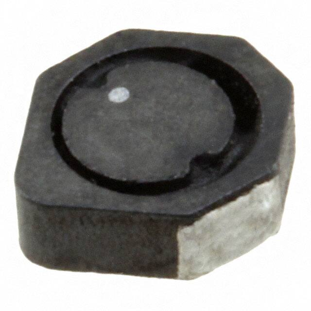


 工商网监
湘ICP备2023018690号
工商网监
湘ICP备2023018690号
