Laird Technologies ,Co., Ltd.
SPECIFICATION FOR APPROVAL
Customer : All
Manufacturer : Laird Technologies Co.,Ltd.
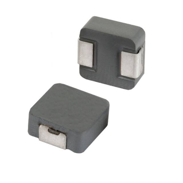
Product : Molding Power Inductor
Laird P/N : MGV1207 Series
Customer P/N : N/A
Issued Date : 2018.2.8
Rev : A
Customer Response
Approved By:
Signature:
Date:
Laird Signature
Approved By
Checked By
Chiang
Siemens Mi
Prepared By
Denny Chen
Laird (Foshan) Magnetics Co., Ltd.
Fu’an Industrial Zone, Leliu Town, Shunde, Foshan City, Guangdong, China 528322
Tel: +86 (757) 25638860 Fax: +86 (757) 25638862
ISO 9001
ISO14001
Email: china@lairdtech.com Website: www.lairdtech.com
OHSAS18001
�Laird Technologies, Co., Ltd
Molding Power Inductor
www.lairdtech.com
MGV1207 Series
Rev: A
Rev
Items
Before
After
Owner
Date
A
─
─
─
Denny
2018.2.8
�Laird Technologies, Co., Ltd
Molding Power Inductor
www.lairdtech.com
MGV1207 Series
Rev: A
SPECIFICATION FOR APPROVAL
1.MECHANICAL & DIMENSIONS
100
A
(UNIT: mm)
E
B
C
A
13.50±0.50
B
12.60±0.40
C
6.20±0.30
D
4.70±0.30
E
2.30±0.30
L
14.20 ref
G
8.00 ref
H
5.00 ref
D
REMARK
L
G
H
2.PART NUMBER NOMENCLATOR:
MGV 1207
A
B
100
C
A: Product Series.
B: Series number, part size
C: Inductance code
M - 1X
D
E
D: Inductance Tolerance. (M=±20% ,N=±30%)
E: "X"=0:Standard catalog part number
"X"=1-9:Controlled customized part or different
performance than std catalog part. And "5-9" is
for automotive grade.
3.EQUIVALENT CIRCUIT:
Page : 1/10
�Laird Technologies, Co., Ltd
Molding Power Inductor
www.lairdtech.com
MGV1207 Series
Rev: A
SPECIFICATION FOR APPROVAL
PART NUMBER
INDUCTANCE
(uH)±20%
MGV1207R15M-10
0.15
55
118
0.49
0.60
MGV1207R22M-10
0.22
53
112
0.47
0.60
MGV1207R30M-10
0.30
48
72
0.60
0.72
MGV1207R33M-10
0.33
46
68
0.65
0.80
MGV1207R40M-10
0.40
44
64
0.70
1.00
MGV1207R47M-10
0.47
41
63
0.90
1.20
MGV1207R56M-10
0.56
37
58
1.05
1.20
MGV1207R68M-10
0.68
35
55
1.25
1.50
MGV1207R82M-10
0.82
33
50
1.5
1.90
MGV12071R0M-10
1.00
30
48
1.7
2.30
MGV12071R5M-10
MGV12071R8M-10
MGV12072R2M-10
MGV12073R3M-10
MGV12074R7M-10
MGV12075R6M-10
MGV12076R8M-10
MGV12078R2M-10
MGV1207100M-10
MGV1207150M-10
MGV1207220M-10
MGV1207330M-10
MGV1207470M-10
1.50
1.80
2.20
3.30
4.70
5.60
6.80
8.20
10.0
15.0
22.0
33.0
47.0
27
24
22
18
13.5
12.5
11.5
10.5
10.0
9.0
9.0
8.0
6.5
45
40
37
30
28
23
18
16
15.5
12.5
12
11
9.5
2.5
3.6
3.8
5.7
7.0
8.5
9.5
12.0
13.2
23.2
32.5
48.0
76.0
3.0
4.0
4.2
6.8
8.4
10.0
11.5
15.5
16.5
28.0
37.0
58.0
90.0
Irms(A) Typ. Isat(A) Typ. DCR(mΩ) Typ DCR(mΩ) Max
REMARK
GENERAL SPECIFICATION:
1, Test conditions(L): 100KHz, 1Vrms
2, Operating temperature: -55℃ to +125℃(Including self-heating)
3, Storage temperature: -10℃ to +40℃
4, Humidity range: 60% RH Max.
5, Heat Rated Current (Irms) will cause the coil temperature rise approximately ∆t of 40°C
6, Saturation Current (Isat) will cause L0 to drop approximately 30%.
7, Part Temperature (Ambient+Temp. Rise) : Should not exceed 125°C under worst case operating conditions.
8, Storage condition (component in its packaging)
Page 2/10
�Laird Technologies, Co., Ltd
Molding Power Inductor
www.lairdtech.com
MGV1207 Series
Rev: A
SPECIFICATION FOR APPROVAL
Characteristics Curve
MGV1207R22M-10
0.16
180
0.14
160
140
0.12
120
0.1
100
0.08
80
0.06
60
0.04
40
0.02
20
0
0.25
160
0.2
60
80
100
120
100
80
0.1
60
40
20
0
140
0
0
50
100
IDC(A)
IDC(A)
MGV1207R33M-10
0.4
140
0.3
120
0.35
120
0.25
100
0.2
80
0.15
60
0.1
40
0.05
20
0
Inductance (uH)
140
Temperature Rise (℃)
0.35
20
40
60
80
80
0.2
60
0.15
40
0.1
20
0
0
100
20
40
60
80
IDC(A)
IDC(A)
MGV1207R40M-10
MGV1207R47M-10
0.4
0.6
120
120
0.5
100
0.4
80
0.3
60
0.2
40
0.1
20
0.35
100
0.3
0.25
80
0.2
60
0.15
40
0.1
20
0.05
0
0
20
40
60
IDC(A)
80
100
100
140
Inductance (uH)
0.45
0
100
0.25
0
0
0
0.3
0.05
Temperature Rise (℃)
Inductance (uH)
MGV1207R30M-10
Inductance (uH)
150
Temperature Rise (℃)
40
120
0.15
0
Temperature Rise (℃)
20
140
0.05
0
0
180
Temperature Rise (℃)
200
Inductance (uH)
0.18
Temperature Rise (℃)
Inductance (uH)
MGV1207R15M-10
0
0
20
40
60
80
100
IDC(A)
Page 3/10
�Laird Technologies, Co., Ltd
Molding Power Inductor
www.lairdtech.com
MGV1207 Series
Rev: A
SPECIFICATION FOR APPROVAL
Characteristics Curve
140
0.8
90
0.6
120
0.7
80
100
0.6
70
0.5
0.4
80
0.3
60
0.2
40
0.1
20
0
Inductance (uH)
0.7
0
40
60
80
40
0.3
30
0.2
20
0.1
10
0
100
0
0
10
20
IDC(A)
90
0.7
80
70
0.6
60
0.5
50
0.4
40
0.3
30
0.2
20
0.1
10
0
Inductance (uH)
0.8
Temperature Rise (℃)
Inductance (uH)
100
30
40
50
1.4
120
1.2
100
1
80
0.8
60
0.6
40
0.4
20
0
60
0
0
10
20
IDC(A)
1.2
2.5
100
2
80
1
60
0.8
0.6
40
0.4
20
0.2
0
0
30
IDC(A)
50
60
40
50
60
140
120
Inductance (uH)
Inductance (uH)
1.4
120
Temperature Rise (℃)
1.6
20
40
MGV12071R8M-10
1.8
10
30
IDC(A)
MGV12071R5M-10
0
60
0.2
0
20
50
MGV12071R0M-10
0.9
10
40
IDC(A)
MGV1207R82M-10
0
30
Temperature Rise (℃)
20
50
0.4
100
1.5
80
1
60
40
0.5
Temperature Rise (℃)
0
60
0.5
Temperature Rise (℃)
MGV1207R68M-10
Temperature Rise (℃)
Inductance (uH)
MGV1207R56M-10
20
0
0
0
10
20
30
40
50
60
IDC(A)
Page 4/10
�Laird Technologies, Co., Ltd
Molding Power Inductor
www.lairdtech.com
MGV1207 Series
Rev: A
SPECIFICATION FOR APPROVAL
Characteristics Curve
MGV12072R2M-10
4
140
160
3.5
120
140
120
1.5
100
80
1
60
40
0.5
Inductance (uH)
20
30
40
50
60
1.5
40
1
20
0
0
0
60
10
20
MGV12075R6M-10
MGV12074R7M-10
7
140
140
6
120
5
100
4
80
3
60
2
40
1
20
120
4
100
3
80
60
2
40
1
20
0
0
0
20
30
Inductance (uH)
Inductance (uH)
5
160
Temperature Rise (℃)
6
10
0
0
40
5
10
25
30
7
120
6
100
5
80
4
60
3
40
2
20
1
0
0
15
IDC(A)
20
25
9
120
8
100
7
Inductance (uH)
140
Temperature Rise (℃)
Inductance (uH)
8
10
20
MGV12078R2M-10
MGV12076R8M-10
5
15
IDC(A)
IDC(A)
0
40
IDC(A)
IDC(A)
0
30
Temperature Rise (℃)
10
80
2
0
0
100
2.5
0.5
20
0
3
6
80
5
60
4
3
40
2
Temperature Rise (℃)
Inductance (uH)
2
180
Temperature Rise (℃)
2.5
Temperature Rise (℃)
MGV12073R3M-10
20
1
0
0
0
5
10
15
20
25
IDC(A)
Page 5/10
�Laird Technologies, Co., Ltd
Molding Power Inductor
www.lairdtech.com
MGV1207 Series
Rev: A
SPECIFICATION FOR APPROVAL
Characteristics Curve
120
14
100
8
80
6
60
4
40
2
0
5
10
15
20
100
12
80
10
8
60
6
40
4
20
2
0
0
20
0
0
25
4
8
35
100
30
80
15
60
10
40
5
20
0
10
100
90
25
70
60
20
50
15
40
30
10
20
10
0
0
0
15
5
10
15
IDC(A)
IDC(A)
MGV1207470M-10
50
MGV1207330M-10
5
0
5
16
80
Inductance (uH)
Inductance (uH)
20
120
Temperature Rise (℃)
MGV1207220M-10
0
12
IDC(A)
IDC(A)
25
120
Temperature Rise (℃)
0
MGV1207150M-10
Temperature Rise (℃)
16
Inductance (uH)
Inductance (uH)
10
140
Temperature Rise (℃)
MGV1207100M-10
12
120
45
Inductance (uH)
35
80
30
25
60
20
40
15
10
Temperature Rise (℃)
100
40
20
5
0
0
0
5
10
15
IDC(A)
Page 6/10
�Laird Technologies, Co., Ltd
Molding Power Inductor
www.lairdtech.com
MGV1207 Series
Rev: A
Recommended Soldering Conditions
■ For Lead-Free Application
Figure 1 . Re-flow Soldering
Within 4 sec
Reflow times: 3 times max
Figure 2 . Hand Soldering
P R E - H E A T IN G
S O L D E R IN G
NATURAL
C O O L IN G
0
TEM PERATURE C
280
230
150
O v e r 1 m in .
G r a d u a l C o o lin g
W ith in 3 s e c .
Hand solder times: 1 time max
page 7/10
�Laird Technologies, Co., Ltd
Molding Power Inductor
www.lairdtech.com
MGV1207 Series
Rev: A
Reliability and Testing Conditions / Pin Type Power Inductors
SMD series(Consumer)
Item
Reference
Additional Requirements
Operating temperature
-55℃~ +125℃(Including self-temperature rise)
range
Storage temperature
and humidity range
High Temperature
Exposure
(Storage)
-10℃ to +40℃ , 60% RH Max
MIL-STD-202 Method 108
85±2℃, 168+24hours
JESD22 Method JA-104
-40℃→+85, transforming interval:20s, 100cycles
Operational Life
MIL-PRF-2
85±℃, 168+24hours
Apply maximum rated voltage and current according part drawing
External Visual
MIL-STD-883 Method 2009
Inspect device construction, marking and workmanship. Electrical
Test not required.
JESD22 Method JB-100
Verify physical dimensions to the applicable device detail
specification. Note: User(s) and Suppliers spec. Electrical Test
not required
MIL-STD-202
Method 204
10~55Hz,1.5mm,
2 hours in each 3mutually
Temperature Cycling
Physical Dimension
Vibration
Resistance to Soldering MIL-STD-202
Method 210
Heat
1. Max. 260±5℃,10±1s, 2 times
2.Solder Composition: Sn/3Ag/0.5Cu
Solderability
J-STD-002
245±5℃, 5±1sec, Solder: Sn/3.0Ag/0.5Cu
Electrical
Characterization
Print Spec
Parametrically test per lot and sample size requirements,
summary to show Min, Max, Mean and Standard deviation at
room as well as Min and Max Operating temperatures
AEC-Q200-005
Board Flex
Terminal Strength(SMD) AEC-Q200-006
2mm,30±1s
10N, 5S, X,Y direct
Page 8/10
�Laird Technologies, Co., Ltd
Molding Power Inductor
www.lairdtech.com
MGV1207 Series
Rev: A
PACKAGING
Reel Dimension
Type A(mm) B(mm)
C(mm)
D(mm)
13'x24 24.4+2/-0 100 ± 2
13+0.5/-0.2
330
B
D
C
A
Tape Dimension
W
E
F
P
24.0±0.3
1.75±0.1
11.50±0.1
16.00±0.1
A0
B0
P2
P0
K0
t
D0
Az
Bz
12.9±0.1 14.10±0.1 2.0±0.1 4.0±0.17.0±0.1 0.35±0.05 1.5Ref. 7.0±0.1 13±0.1
Packaging Quantity
P/N
Chip/Reel
MGV1207 Series
500pcs
Size
Peeling Off Force
The force peeling off cove tape is 10 to 100 grams
in the arrow direction under the following conditions
Room Temp
(℃)
Room
Humidity
Room atrn
(hPa)
Teaming
Speed
5~35
45~85
860~1060
300
※Storage Conditions
1. Temperature and humidity conditions: -10-+40℃
and 60% RH.
2. Recommended products should be used within 12 months
from the time of manufacturing.
3. The packaging material should be kept where no chlorine
or sulfur exists in the air.
4. Allowable stacking condition of Packaging box:max height 1.5m or 5 boxes stacking
Page 9/10
�Laird Technologies, Co., Ltd
Molding Power Inductor
www.lairdtech.com
MGV1207 Series
Rev: A
SPECIFICATION FOR APPROVAL
MATERIAL IDENTIFICATION
ITEM
DESCRIPTION
1
Powder
2
Copper Wire
3
4
Spec
SGS No.
SUPPLIERS
Iron Powder
SCL03H001687001
Laird
AIB
SCL01G06040701E
PACIFIC
Coating
Paint
RHS01G006468001
BERLIN
Clip
Clip
CAN1406178103
HUIGAO
Page 10/10
�


 工商网监
湘ICP备2023018690号
工商网监
湘ICP备2023018690号
