No.:
Date:
RLC-K-HTS-0001
2017. 4. 21
/17
Data sheet
Title:
FIXED THICK FILM CHIP RESISTORS; RECTANGULAR TYPE &
LOW OHM
Style:
RLC10, 16, 20, 32, 35, 50, 63
AEC-Q200 qualified
RoHS COMPLIANCE ITEM
Halogen and Antimony Free
Note: ・Stock conditions
Temperature: +5°C ∼ +35°C
Relative humidity: 25% ∼ 75%
The period of guarantee: Within 2 year from shipmen t by the company.
Solderability shall be satisfied.
・Product specification contained in this data sheet
are subject to change at any time without notice
・If you have any questions or a Purchasing Specification for any quality
Agreement is necessary, please contact our sales staff.
Hokkaido Research Center
Approval by: T. Sannomiya
Drawing by: M. Shibuya
�Title:
No: RLC−K−HTS−0001
/17
FIXED THICK FILM CHIP RESISTORS; RECTANGULAR TYPE AND LOW OHM
RLC10, 16, 20, 32, 35, 50, 63
Page: 1/17
1. Scope
1.1 This data sheet covers the detail requirements for fixed thick film chip resistors; rectangular type and low ohm, style of
RLC10, 16, 20, 32, 35, 50, 63.
1.2 Applicable documents
JIS C 5201−1: 2011, JIS C 5201−8: 2014, JIS C 5201−8−1: 2014
IEC60115−1: 2008, IEC60115−8: 2009, IEC60115−8−1: 2014
EIAJ RC−2144−2010
2. Classification
Type designation shall be the following form.
(Example)
RLC
1
20
2
K
3
R470
4
J
5
TP
6
Style
1 Fixed thick film chip resistors; rectangular type and low ohm
2 Size
3 Temperature coefficient of resistance
K
−(Dash)
L
Style
±100×10-6/ °C
Standard
See Paragraph 3.2
4 Rated resistance Rated resistance and symbol shall be in accordance with Sub-clause 3.3.
5 Tolerance on rated resistance
F
±1%
G
±2%
J
±5%
6 Packaging form
B
Bulk (loose package)
TH
Paper taping
TP
TE
Embossed taping
Product specification contained in this data sheet are subject to change at any time without notice.
If you have any questions or a Purchasing Specification for any quality agreement is necessary, please contact our sales staff.
Issue: KAMAYA ELECTRIC CO., LTD. Research & Development Department HOKKAIDO Research center Last update: 2017.4.21
�Title:
No: RLC−K−HTS−0001
/17
FIXED THICK FILM CHIP RESISTORS; RECTANGULAR TYPE AND LOW OHM
RLC10, 16, 20, 32, 35, 50, 63
Page: 2/17
3. Rating
The ratings shall be in accordance with Table−1.
3.1 Temperature coefficient of resistance: K & −(Dash) code
Table−1(1)
Rated
Rated
Temperature coefficient of
Style
dissipation
current
resistance (10–6/ °C)
(W)
range (A)
K
±100
RLC10
0.125
0.11∼1.11
0∼+200
−(Dash)
0∼+300
RLC16
RLC20
RLC32
0.25
0.33
0.5
K
±100
−(Dash)
0∼+200
0∼+250
K
±100
−(Dash)
0∼+200
0∼+250
K
±100
−(Dash)
0∼+200
0∼+250
±100
0∼+200
0∼+250
±100
0~+200
0~+250
±100
0∼+200
0∼+250
0.14∼1.58
0.15∼2.56
0.18∼3.16
K
RLC35
0.66
0.44∼3.63
RLC50
0.75
0.47∼3.87
−(Dash)
K
−(Dash)
K
RLC63
1.0
0.55∼4.47
RLC10
RLC16
RLC20
Limiting element
voltage(V)
1.11
1.41
1.58
RLC32
1.81
RLC35
1.47
RLC50
1.56
RLC63
1.82
Style
−(Dash)
Isolation voltage
(V)
Rated resistance
range(Ω)
3.6∼10
0.47∼3.3
0.1∼0.43
3.6∼10
0.47∼3.3
0.2∼0.43
0.1∼0.18
3.6∼10
0.47∼3.3
0.2∼0.43
0.05∼0.18
3.6∼10
0.47∼3.3
0.2∼0.43
0.05∼0.18
0.47∼3.3
0.2∼0.43
0.05∼0.18
0.47∼3.3
0.2∼0.43
0.05∼0.18
0.47∼3.3
0.2∼0.43
0.05∼0.18
Tolerance on rated resistance
F(±1%), J(±5%)
F(±1%), G(±2%), J(±5%)
F(±1%), J(±5%)
F(±1%), J(±5%)
F(±1%)
G(±2%)
J(±5%)
F(±1%), J(±5%)
F(±1%)
G(±2%)
J(±5%)
F(±1%), J(±5%)
F(±1%)
G(±2%)
J(±5%)
F(±1%)
G(±2%)
J(±5%)
F(±1%)
G(±2%)
J(±5%)
F(±1%)
G(±2%)
J(±5%)
Category temperature
range (°C)
100
−55∼+155
500
Product specification contained in this data sheet are subject to change at any time without notice.
If you have any questions or a Purchasing Specification for any quality agreement is necessary, please contact our sales staff.
Issue: KAMAYA ELECTRIC CO., LTD. Research & Development Department HOKKAIDO Research center Last update: 2017.4.21
�Title:
No: RLC−K−HTS−0001
/17
FIXED THICK FILM CHIP RESISTORS; RECTANGULAR TYPE AND LOW OHM
RLC10, 16, 20, 32, 35, 50, 63
Page: 3/17
3.2 Temperature coefficient of resistance: L code
Table−1(2)
Style
Rated
dissipation
(W)
Rated
current
range (A)
RLC10
0.063
0.26∼1.12
L
RLC16
0.1
0.33∼3.16
L
RLC20
0.25
0.52∼5.0
L
RLC32
0.5
0.74∼7.07
L
Temperature coefficient of
resistance (10–6/ °C)
RLC35
0.66
0.85∼8.12
L
RLC50
0.75
0.90∼8.66
L
RLC63
1.0
1.04∼10
L
Style
RLC10
RLC16
RLC20
RLC32
RLC35
RLC50
RLC63
Limiting element voltage (V)
0.23
0.30
0.47
0.67
0.77
0.82
0.95
Rated resistance
range(Ω)
±300
±800
±1500
±300
±800
±1200
±2000
±200
±300
±600
±1000
±1200
±1500
±200
±300
±600
±1000
±1200
±1500
0.51∼0.91
0.10∼0.50
0.05∼0.091
0.51∼0.91
0.10∼0.50
0.039∼0.091
0.01∼0.036
0.51∼0.91
0.39∼0.50
0.10∼0.36
0.05∼0.091
0.02∼0.047
0.01∼0.018
0.51∼0.91
0.39∼0.50
0.10∼0.36
0.05∼0.091
0.02∼0.047
0.01∼0.018
±200
±300
±600
±1000
±1200
±1500
±200
±300
±600
±1000
±1200
±1500
±200
±300
±600
±1000
±1200
±1500
0.51∼0.91
0.39∼0.50
0.10∼0.36
0.05∼0.091
0.02∼0.047
0.01∼0.018
0.51∼0.91
0.39∼0.50
0.10∼0.36
0.05∼0.091
0.02∼0.047
0.01∼0.018
0.51∼0.91
0.39∼0.50
0.10∼0.36
0.05∼0.091
0.02∼0.047
0.01∼0.018
Isolation voltage (V)
Tolerance on rated resistance
F(±1%), J(±5%)
F(±1%), J(±5%)
F(±1%), J(±5%)
F(±1%), J(±5%)
F(±1%), J(±5%)
F(±1%), J(±5%)
F(±1%), J(±5%)
Category temperature range (°C)
100
−55∼+155
500
Product specification contained in this data sheet are subject to change at any time without notice.
If you have any questions or a Purchasing Specification for any quality agreement is necessary, please contact our sales staff.
Issue: KAMAYA ELECTRIC CO., LTD. Research & Development Department HOKKAIDO Research center Last update: 2017.4.21
�Title:
No: RLC−K−HTS−0001
/17
FIXED THICK FILM CHIP RESISTORS; RECTANGULAR TYPE AND LOW OHM
RLC10, 16, 20, 32, 35, 50, 63
Page: 4/17
3.3 Rated resistance
The rated resistance shall be in accordance with Table−2
Table−2
Rated resistance
Rated resistance
Symbol
Rated resistance [mΩ]
Rated resistance [mΩ]
10
R010
100
11
R011
110
12
R012
120
13
R013
130
15
R015
150
16
R016
160
18
R018
180
20
R020
200
22
R022
220
24
R024
240
25
R025
250
27
R027
270
30
R030
300
33
R033
330
36
R036
360
39
R039
390
40
R040
400
43
R043
430
47
R047
470
50
R050
500
51
R051
510
56
R056
560
60
R060
600
62
R062
620
65
R065
650
68
R068
680
70
R070
700
75
R075
750
80
R080
800
82
R082
820
90
R090
900
91
R091
910
3.4 Climatic category
55/155/56
3.5 Stability class
5%
Symbol
R100
R110
R120
R130
R150
R160
R180
R200
R220
R240
R250
R270
R300
R330
R360
R390
R400
R430
R470
R500
R510
R560
R600
R620
R650
R680
R700
R750
R800
R820
R900
R910
Lower category temperature
Upper category temperature
Duration of the damp heat, steady state test
Rated resistance
Rated resistance [Ω]
1.0
1.1
1.2
1.3
1.5
1.6
1.8
2.0
2.2
2.4
2.7
3.0
3.3
3.6
3.9
4.3
4.7
5.1
5.6
6.2
6.8
7.5
8.2
9.1
10
Symbol
1R00
1R10
1R20
1R30
1R50
1R60
1R80
2R00
2R20
2R40
2R70
3R00
3R30
3R60
3R90
4R30
4R70
5R10
5R60
6R20
6R80
7R50
8R20
9R10
100
−55 °C
+155 °C
56days
Limits for change of resistance:
−for long−term tests
±5%
−for short−term tests
±1%
Product specification contained in this data sheet are subject to change at any time without notice.
If you have any questions or a Purchasing Specification for any quality agreement is necessary, please contact our sales staff.
Issue: KAMAYA ELECTRIC CO., LTD. Research & Development Department HOKKAIDO Research center Last update: 2017.4.21
�Title:
No: RLC−K−HTS−0001
/17
FIXED THICK FILM CHIP RESISTORS; RECTANGULAR TYPE AND LOW OHM
RLC10, 16, 20, 32, 35, 50, 63
Page: 5/17
3.6 Derating
The derated values of dissipation at temperature in excess of 70 °C shall be as indicated by the following curve.
100
Percentage
of the rated
dissipation
(%)
Area of recommended
operation
0
−55
70
155
Ambient temperature (°C)
Figure−1 Derating curve
3.7 Rated voltage
d.c. or a.c. r.m.s. voltage calculated from the square root of the product of the rated resistance and the rated dissipation.
E: Rated voltage (V)
E =
P · R
P: Rated dissipation (W)
R: Rated resistance (Ω)
Limiting element voltage can only be applied to resistors when the resistance value is equal to or higher than the critical
resistance value.
At high value of resistance, the rated voltage may not be applicable.
3.8 Rated current
The rated current calculated from the square root of the quotient of the rated resistance and the rated dissipation.
I: Rated current (A)
I =
P / R
P: Rated dissipation (W)
R: Rated resistance (Ω)
The rated current shall be corresponding to rated voltage.
4. Packaging form
The standard packaging form shall be in accordance with Table−3.
Table−3
Standard packaging
Symbol
Packaging form
quantity / units
B
Bulk (loose package)
1,000 pcs.
TH
Paper taping
8mm width, 2mm pitches
10,000 pcs.
TP
Paper taping
8mm width, 4mm pitches
5,000 pcs.
8mm width, 4mm pitches
Embossed
TE
4,000 pcs.
taping
12mm width, 4mm pitches
Application
RLC10, 16, 20, 32, 35, 50, 63
RLC10
RLC16, 20, 32
RLC35
RLC50, 63
Product specification contained in this data sheet are subject to change at any time without notice.
If you have any questions or a Purchasing Specification for any quality agreement is necessary, please contact our sales staff.
Issue: KAMAYA ELECTRIC CO., LTD. Research & Development Department HOKKAIDO Research center Last update: 2017.4.21
�Title:
No: RLC−K−HTS−0001
/17
FIXED THICK FILM CHIP RESISTORS; RECTANGULAR TYPE AND LOW OHM
RLC10, 16, 20, 32, 35, 50, 63
Page: 6/17
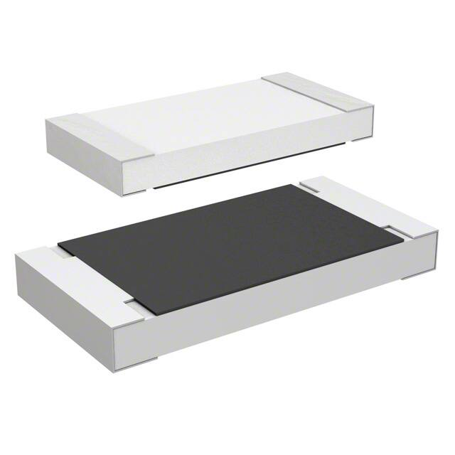
5. Dimensions
5.1 The resistor shall be of the design and physical dimensions in accordance with Figure−2 and Table−4.
W
L
c
d
d
H
c
Figure−2
5.1.1 Temperature coefficient of resistance: K & −(Dash) code
Table−4(1)
Style
L
W
H
RLC10
1.0 ± 0.05
0.5 ± 0.05
0.35 ± 0.05
+0.15
RLC16
0.8 −0.05
1.6±0.1
0.45±0.1
RLC20
2.0±0.1
1.25±0.10
0.6±0.1
RLC32
3.1±0.2
1.6±0.15
0.6±0.1
RLC35
3.1±0.2
2.5±0.15
0.6±0.15
RLC50
5.0±0.2
2.5±0.15
0.6±0.15
RLC63
6.3±0.2
3.2±0.15
0.6±0.15
c
0.2 ± 0.1
0.3±0.1
0.4±0.2
0.5±0.25
0.5±0.25
0.6±0.2
0.6±0.2
Unit: mm
d
+0.05
0.25 −0.10
0.3±0.1
0.4±0.2
+0.2
0.3 −0.1
+0.2
0.3 −0.1
0.6±0.2
0.6±0.2
c
0.2±0.1
0.3±0.1
0.4±0.2
0.5±0.2
0.5±0.2
0.65±0.25
0.65±0.25
Unit: mm
d
+0.05
0.25 −0.10
0.3±0.2
0.4±0.2
0.45±0.20
0.5±0.2
0.6±0.25
0.9±0.25
5.1.2 Temperature coefficient of resistance: L code
Style
RLC10
RLC16
RLC20
RLC32
RLC35
RLC50
RLC63
L
1.0±0.05
1.6±0.1
2.0±0.1
3.1±0.1
3.1±0.1
5.0±0.2
6.4±0.2
Table−4(2)
W
H
0.5±0.05
0.35±0.05
0.8±0.1
0.45±0.15
1.25±0.10
0.5±0.15
1.6±0.1
0.6±0.15
2.6±0.1
0.55±0.10
2.5±0.2
0.55±0.10
3.2±0.2
0.6±0.1
5.2 Net weight (Reference)
Style
Net weight (mg)
RLC10
0.6
RLC16
2
RLC20
5
RLC32
9
RLC35
16
RLC50
25
RLC63
40
Product specification contained in this data sheet are subject to change at any time without notice.
If you have any questions or a Purchasing Specification for any quality agreement is necessary, please contact our sales staff.
Issue: KAMAYA ELECTRIC CO., LTD. Research & Development Department HOKKAIDO Research center Last update: 2017.4.21
�Title:
No: RLC−K−HTS−0001
/17
FIXED THICK FILM CHIP RESISTORS; RECTANGULAR TYPE AND LOW OHM
RLC10, 16, 20, 32, 35, 50, 63
Page: 7/17
6. Marking
The rated resistance of RLC10 should not be marked.
6.1 RLC20,32,35,50,63
The rated resistance shall be marked in 4 characters consisting of 3 figures or 3 figures and a letter and marked on over coat
side.
(Example) “R050” → 0.05 [Ω] (R


 工商网监
湘ICP备2023018690号
工商网监
湘ICP备2023018690号
