ISD-DEMO15D00 REV_A
ISD-DEMO15D00 User Manual
Version 0.1
Publication Release Date: Jan 20, 2011
-1-
Revision 0.1
�ISD-DEMO15D00 REV_A
Contents
Overview ....................................................................................................................................................... 3
Introduction .................................................................................................................................................. 5
Board Configuration...................................................................................................................................... 7
Operations under VPE ................................................................................................................................. 10
Standalone Operation ................................................................................................................................. 11
Board Schematic ......................................................................................................................................... 12
Publication Release Date: Jan 20, 2011
-2-
Revision 0.1
�ISD-DEMO15D00 REV_A
Overview
This manual is for ISD-DEMO15D00 Rev_A.
Figure 1 – Top view of ISD-DEMO15D00 Rev-A board
Figure 2 – Bottom view of ISD-DEMO15D00 Rev-A board
Publication Release Date: Jan 20, 2011
-3-
Revision 0.1
�ISD-DEMO15D00 REV_A
Figure 3 – ISD_DEMO15D00 connected with ISD-ES_MINI_USB (dongle) board
Publication Release Date: Jan 20, 2011
-4-
Revision 0.1
�ISD-DEMO15D00 REV_A
Introduction
ISD_DEMO15D00 is to be used with ISD-ES_MINI_USB dongle. The complete evaluation kit for ISDDEMO15D00 consists of the following:
-
-
Hardware
o ISD-DEMO15D00 board
o ISD-ES_USB_MINI board
Software
o ISD-VPE15D00 can be downloaded from website: http://www.nuvotonusa.com/ISD15D00/vpe
User needs to fill out and submit the form on the website to request the username and
password. Unfortunately, this registration process is not fully automatic yet when this manual is
created. Instead, Nuvoton staff will generate the username and password based on the
information received, and send them to user via email.
System Requirements
•
•
PC running Windows Vista, XP, NT, or 2000.
Support for Windows 7 will be available soon.
Figure 4 below shows a complete evaluation environment for ISD15D00 series devices. The ISD USB
dongle provides the communication link between ISD-DEMO15D00 board and host PC. All the
operations are initiated from VPE, a GUI application which runs on Windows PC.
Publication Release Date: Jan 20, 2011
-5-
Revision 0.1
�ISD-DEMO15D00 REV_A
Figure 4 – A complete evaluation environment for ISD15D00 device
Publication Release Date: Jan 20, 2011
-6-
Revision 0.1
�ISD-DEMO15D00 REV_A
Board Configuration
Board Layout
Jumper settings
J1: Aux Output
-
Installing jumper at right position will connect AUX and AMP feed AUX output from
ISD15D00 to onboard audio amplifier ISD8101
User should not install jumper at left position, which will connect AUX and VSSA
together. The Left two pins of J1 are for the purpose of further evaluation. User can use
these two pins as input to feed his/her own amplifier.
J2: Battery power connector.
Publication Release Date: Jan 20, 2011
-7-
Revision 0.1
�ISD-DEMO15D00 REV_A
J3: AUXIN vs. VSSA user can use J3 to feed AUXIN input to ISD15D00 from here.
J4: 2x5 header for connecting ISD-ES_MINI_USB dongle. Please note: two boards must connect
each other with both top side up. For USB dongle board, it has a small window at its top side.
Please note: It could cause hardware damage if the two boards are not connected correctly.
Figure 5 – connect ISD15D00 demo board with the USB dongle.
J5: Install Jumper at J5 will connect AMP_EN with VCCA, thus enable the on board audio
amplifier ISD8101. To disable ISD8101, remove the J5 jumper.
J6: J6 is the place for user to select ISD15D00 VCCA. Installing a jumper vertically will make the
VCCA equal VCC. If user wants to hear higher volume, and since VCCA can be higher than VCC,
user can use the two horizontal pins of J6 to connect his/her own VCCA power supply. So, user
should not install a jumper horizontally (although there is no harm doing so).
J7: 2x8 connection header for connecting with ISD-ES15D00_USB board or ISD-ES15100_USB mother
board.
Publication Release Date: Jan 20, 2011
-8-
Revision 0.1
�ISD-DEMO15D00 REV_A
Figure 6 – ISD15D00 is connected onto ISD-ES15D00_USB mother board
J8: two-pin connector for speaker. This is the output from audio amplifier ISD8101.
J9: Clock source selection.
-
Install a jumper at top position to connect the top two pins ISD15D00 device clock can be
from internal oscillator with external resistor.
Install a jumper at bottom position to connect the bottom two pins ISD15D00 device clock
can be from external crystal.
Please note: the silk label on board for J9 XTAL “XTALIN” and “Ext_Res” should switch the position
on Rev-A board. Please bear this mind to avoid confustion.
Publication Release Date: Jan 20, 2011
-9-
Revision 0.1
�ISD-DEMO15D00 REV_A
Figure 7 – Clock source selection
J10: ISD15D00 PWM output jack to speaker.
J11: ISD15D00 I2S signal header.
J12: ISD15D00 PWM output header to speaker.
Operations under VPE
•
•
•
Connect a ISD15D00 demo board to USB dongle
Plug in USB dongle into a PC USB port
Launch ISD15D00 VPE
These operations do not have to follow a special order. USB dongle is hot pluggable, and so is the demo
board. However, during digital programming, demo board needs to be connected otherwise the
integrity of flash image cannot be guaranteed.
User can refer VPE user manual for the operation guide. VPE user manual can be found in VPE
installation folder; i.e. usually it is under: C:\program files\ISD-VPE15D00.
Publication Release Date: Jan 20, 2011
- 10 -
Revision 0.1
�ISD-DEMO15D00 REV_A
Standalone Operation
There are 8 push buttons on ISD-DEMO15D00 board which allow user to evaluate the ISD15D00 feature
of trigger play. Figure 8 below show thes operation environment.
Figure 8 – ISD15D00 demo board standalone evaluation.
Publication Release Date: Jan 20, 2011
- 11 -
Revision 0.1
�ISD-DEMO15D00 REV_A
Board Schematic
Publication Release Date: Jan 20, 2011
- 12 -
Revision 0.1
�
很抱歉,暂时无法提供与“NU-ISDMINUSB”相匹配的价格&库存,您可以联系我们找货
免费人工找货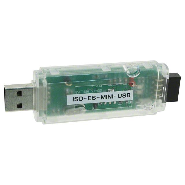


 工商网监
湘ICP备2023018690号
工商网监
湘ICP备2023018690号
