Radio FeatherWing
Created by lady ada
https://learn.adafruit.com/radio-featherwing
Last updated on 2022-07-11 01:28:44 PM EDT
©Adafruit Industries
Page 1 of 67
�Table of Contents
Overview
5
• RFM69 Specs
• RFM9x Specs
Pinouts
•
•
•
•
SPI Data Pins (Fixed)
SPI Control Pins (Flexible)
RFM GPIO
Antenna
Wiring
•
•
•
•
32
Design Considerations
Wiring With Breakout
Usage with All-In-One Feather M0
Module Install
Usage
Beyond RX & TX
Using the RFM9X Radio
•
•
•
•
•
19
"Raw" vs Packetized
Arduino Libraries
RadioHead Library example
Basic RX & TX example
Basic Transmitter example code
Basic receiver example code
Radio Freq. Config
Configuring Radio Pinout
Setup
Initializing Radio
Basic Transmission Code
Basic Receiver Code
Basic Receiver/Transmitter Demo w/OLED
Addressed RX and TX Demo
CircuitPython for RFM69
•
•
•
•
•
•
12
Antenna Options
Wire Antenna
uFL Connector
SMA Edge-Mount Connector
Using the RFM69 Radio
•
•
•
•
•
•
•
•
•
•
•
•
•
•
11
ESP8266 Wiring
Feather 32u4
Feather M0
Other Boards
Assembly
•
•
•
•
8
42
Arduino Library
RadioHead RFM9x Library example
Basic RX & TX example
Transmitter example code
Receiver example code
©Adafruit Industries
Page 2 of 67
�•
•
•
•
•
•
Feather Radio Pinout
Frequency
Setup
Initializing Radio
Transmission Code
Receiver Code
CircuitPython for RFM9x LoRa
•
•
•
•
•
•
54
Design Considerations
Wiring With Breakout
Usage with All-In-One Feather M0
Module Install
Usage
Beyond RX & TX
Radio Range F.A.Q.
64
Downloads
66
• Datasheets & Files
• Schematic
• Fabrication Print
©Adafruit Industries
Page 3 of 67
�©Adafruit Industries
Page 4 of 67
�Overview
Add short-hop wireless to your Feather with these Radio Featherwings. These addons for any Feather board will let you integrate packetized radio (with the RFM69
radio) or LoRa radio (with the RFM9x's). These radios are good options for kilometerrange radio, and paired with one of our WiFi, cellular or Bluetooth Feathers, will let
you bridge from 433/900 MHz to the Internet or your mobile device.
These radio modules come in four variants (two modulation types and two
frequencies) The RFM69's are easiest to work with, and are well known and
©Adafruit Industries
Page 5 of 67
�understood. The LoRa radios are exciting, longer-range and more powerful but also
more expensive.
• RFM69 @ 433 MHz - basic packetized FSK/GFSK/MSK/GMSK/OOK radio at 433
MHz for use in Europe ITU 1 license-free ISM, or for amateur use with restrictions
(check your local amateur regulations!)
• RFM69 @ 900 MHz - basic packetized FSK/GFSK/MSK/GMSK/OOK radio at 868
or 915 MHz for use in Americas ITU 2 license-free ISM, or for amateur use with
restrictions (check your amateur regulations!)
• RFM98 @ 433 MHz - LoRa capable radio at 433 MHz for use in Europe ITU 1
license-free ISM, or for amateur use with restrictions (check your local amateur
regulations!)
• RFM95 @ 900 MHz - LoRa capable radio at 868 or 915 MHz for use in Americas
ITU 2 license-free ISM, or for amateur use with restrictions (check your local
amateur regulations!)
The radio modules themselves have the same pinout so the PCB is the same, but the
library usage and wiring may vary. All use SPI for interfacing, and there are great
Arduino libraries available for both.
RFM69 Specs
• SX1231 based module with SPI interface
• Packet radio with ready-to-go Arduino libraries
• Uses the license-free ISM bands
©Adafruit Industries
Page 6 of 67
�• +13 to +20 dBm up to 100 mW Power Output Capability (power output selectable
in software)
• 50mA (+13 dBm) to 150mA (+20dBm) current draw for transmissions
• Range of approx. 350 meters, depending on obstructions, frequency, antenna
and power output
• Create multipoint networks with individual node addresses
• Encrypted packet engine with AES-128
RFM9x Specs
• SX127x LoRa® based module with SPI interface
• Packet radio with ready-to-go Arduino libraries
• Uses the license-free ISM bands
• +5 to +20 dBm up to 100 mW Power Output Capability (power output selectable
in software)
• ~300uA during full sleep, ~120mA peak during +20dBm transmit, ~40mA during
active radio listening.
• Our initial tests with default library settings: over 1.2mi/2Km line-of-sight with
wire quarter-wave antennas. (With setting tweaking and directional antennas,
20Km is possible (https://adafru.it/mGa)).
Currently tested to work with the Feather ESP8266, Feather 32u4, Feather M0,
WICED Feather (RFM69 library only) and Teensy 3 Feather series, some wiring is
required to configure the FeatherWing for the chipset you plan to use.
©Adafruit Industries
Page 7 of 67
�All radios are sold individually and can only talk to radios of the same part number.
E.g. RFM69 900 MHz can only talk to RFM69 900 MHz, LoRa 433 MHz can only talk to
LoRa 433, etc.
Each radio 'Wing comes with some header. Some soldering is required to attach the
header. You will need to cut and solder on a small piece of wire (any solid or stranded
core is fine) in order to create your antenna. Optionally you can pick up a uFL or SMA
edge-mount connector and attach an external duck.
Pinouts
SPI Data Pins (Fixed)
The three SPI data pins (MOSI/MISO/SCK) are hardwired to these three pads, which
are use for the default SPI interface on all Feathers:
SPI Control Pins (Flexible)
You also need three more pins to control the radio: CS, RST and IRQ
©Adafruit Industries
Page 8 of 67
�Since there is no guaranteed Feather pin that is interrupt-capable, we set it up so you
can fly-wire these three to any three pins available. For the non-Serial/IC pins on the
right, we name them A thru F. We also indicate the RX/TX/SDA/SCL pins if you need
to use those:
Wire them with three short jumpers like so:
RFM GPIO
There's some other GPIO pins that you may want to use - they can be configured to
give you notice of things like packet completion or incoming data. They're all on the
left. DIO0 is also known as IRQ so we don't have that duplicated on the left breakouts
©Adafruit Industries
Page 9 of 67
�Antenna
For an antenna, you have three options:
• Plain wire antenna (cut a quarter-wavelength piece and solder it into the pad/
hole
• uFL connector (not included) (http://adafru.it/1661), which can be soldered and
then used to attach a uFL antenna or adapter
• SMA edge-launch (not included) (http://adafru.it/1865), for use with any SMA
connector
©Adafruit Industries
Page 10 of 67
�Wiring
Because each Feather uses a different processor, there is some light wiring that
needs to be done to configure the radio pins. In particular, an interrupt-capable pin is
required for IRQ but there is no one irq pin that is the same on all the Feathers!
So, while MOSI/MISO/SCK are fixed, you will want to solder three short wires for CS,
RST and IRQ
Here is our tested/suggested wiring configurations and code snippets for defining the
pins
ESP8266 Wiring
The ESP does not have a lot of spare pins, and the SPI pins are taken, so here's what
we've tested that works:
#define RFM95_CS 2
#define RFM95_RST 16
#define RFM95_INT 15
#define
#define
#define
#define
RFM69_CS
RFM69_RST
RFM69_IRQ
RFM69_IRQN
// "E"
// "D"
// "B"
2
16
15
digitalPinToInterrupt(RFM69_IRQ )
This leaves the I2C default pins (4 and 5) available
©Adafruit Industries
Page 11 of 67
�Feather 32u4
The 32u4 doesn't have a lot of IRQs and the only ones available are on pins 0, 1, 2, 3
which are also the Serial RX/TX and I2C pins. So it's not great because you have to
give up one of those pins.
#define RFM95_CS 10
#define RFM95_RST 11
#define RFM95_INT 2
#define
#define
#define
#define
RFM69_CS
RFM69_RST
RFM69_IRQ
RFM69_IRQN
// "B"
// "A"
// "SDA" (only SDA/SCL/RX/TX have IRQ!)
10
// "B"
11
// "A"
2
// "SDA" (only SDA/SCL/RX/TX have IRQ!)
digitalPinToInterrupt(RFM69_IRQ )
Feather M0
The Feather M0 is really easy to use, a ton of interrupts so wiring is easy
#define RFM95_CS 10
#define RFM95_RST 11
#define RFM95_INT 6
#define
#define
#define
#define
RFM69_CS
RFM69_RST
RFM69_IRQ
RFM69_IRQN
// "B"
// "A"
// "D"
10
// "B"
11
// "A"
6
// "D"
digitalPinToInterrupt(RFM69_IRQ )
Other Boards
For other boards like the ESP32 or nRF52, any pin can be an interrupt, so feel free to
use any wiring setup you like!
Assembly
Antenna Options
These radio Wings do not have a built-in antenna. Instead, you have three options for
attaching an antenna. For most low cost radio nodes, a wire works great. If you need
to put the radio into an enclosure, soldering in uFL and using a uFL to SMA adapter
©Adafruit Industries
Page 12 of 67
�will let you attach an external antenna. You can also solder an SMA edge-mount
connector directly
Wire Antenna
A wire antenna, aka "quarter wave whip antenna" is low cost and works very well! You
just have to cut the wire down to the right length.
Cut a stranded or solid core wire the the
proper length for the module/frequency
433 MHz - 6.5 inches, or 16.5 cm
868 MHz - 3.25 inches or 8.2 cm
915 MHz - 3 inches or 7.8 cm
Strip a mm or two off the end of the wire,
tin and solder into the ANT pad.
uFL Connector
If you want an external antenna that is a few inches away from the radio, you need to
do a tiny bit more work but its not too difficult.
You'll need to get an SMT uFL connector, these are fairly standard (http://adafru.it/
1661)
You'll also need a uFL to SMA adapter (http://adafru.it/851) (or whatever adapter you
need for the antenna you'll be using, SMA is the most common
Of course, you will also need an antenna of some sort, that matches your radio
frequency
uFL connectors are rated for 30 connection cycles, but be careful when
connecting/disconnecting to not rip the pads off the PCB. Once a uFL/SMA
adapter is connected, use strain relief!
©Adafruit Industries
Page 13 of 67
�Start by melting solder onto the center
signal pad
Check the bottom of the uFL connector,
note that there's two large side pads
(ground) and a little inlet pad. The other
small pad is not used!
©Adafruit Industries
Page 14 of 67
�Solder in the first pad while holding the
uFL steady
©Adafruit Industries
Page 15 of 67
�Solder in the two side pads, they are used
for signal and mechanical connectivity so
make sure there's plenty of solder
Once done, check your work visually
SMA Edge-Mount Connector
These strong edge connectors are used for many 'duck' antennas, and can also be
panel mounted
©Adafruit Industries
Page 16 of 67
�You'll need an SMA (or, if you need RPSMA for some reason) Edge-Mount
connector with 1.6mm spacing
The SMA connector 'slides on' the top of
the PCB
©Adafruit Industries
Page 17 of 67
�Solder all 5 connections (4 ground/
mechanical and 1 signal)
©Adafruit Industries
Page 18 of 67
�Use plenty of solder to make sure you
have a good strong mechanical
connection. The duck antennas are long
and make great levers, so they could pry
apart the solder joints if not soldered well
Using the RFM69 Radio
This page is shared between the RFM69
breakout and the all-in-one Feather
RFM69's. The example code and overall
functionality is the same, only the pinouts
used may differ! Just make sure the
example code is using the pins you have
wired up.
Before beginning make sure you have your Arduino or Feather working smoothly, it
will make this part a lot easier. Once you have the basic functionality going - you can
upload code, blink an LED, use the serial output, etc. you can then upgrade to using
the radio itself.
©Adafruit Industries
Page 19 of 67
�Note that the sub-GHz radio is not designed for streaming audio or video! It's best
used for small packets of data. The data rate is adjustable but its common to stick to
around 19.2 Kbps (thats bits per second). Lower data rates will be more successful in
their transmissions
You will, of course, need at least two paired radios to do any testing! The radios must
be matched in frequency (e.g. 900 MHz & 900 MHz are ok, 900 MHz & 433 MHz are
not). They also must use the same encoding schemes, you cannot have a 900 MHz
RFM69 packet radio talk to a 900 MHz RFM9x LoRa radio.
"Raw" vs Packetized
The SX1231 can be used in a 'raw rx/tx' mode where it just modulates incoming bits
from pin #2 and sends them on the radio, however there's no error correction or
addressing so we wont be covering that technique.
Instead, 99% of cases are best off using packetized mode. This means you can set up
a recipient for your data, error correction so you can be sure the whole data set was
transmitted correctly, automatic re-transmit retries and return-receipt when the packet
was delivered. Basically, you get the transparency of a data pipe without the
annoyances of radio transmission unreliability
Arduino Libraries
These radios have really great libraries already written, so rather than coming up with
a new standard we suggest using existing libraries such as LowPowerLab's RFM69
Library (https://adafru.it/mCz) and AirSpayce's Radiohead library (https://adafru.it/mCA)
which also suppors a vast number of other radios
These are really great Arduino Libraries, so please support both companies in thanks
for their efforts!
We recommend using the Radiohead library - it is very cross-platform friendly and
used a lot in the community!
RadioHead Library example
To begin talking to the radio, you will need to download our small fork of the
Radiohead from our github repository (https://adafru.it/vgE). You can do that by
©Adafruit Industries
Page 20 of 67
�visiting the github repo and manually downloading or, easier, just click this button to
download the zip
Download RadioHead Library
https://adafru.it/vgF
Rename the uncompressed folder RadioHead and check that the RadioHead folder
contains files like RH_RF69.cpp and RH_RF69.h (and many others!)
Place the RadioHead library folder in your arduinosketchfolder/libraries/ folder.
You may need to create the libraries subfolder if it's your first library. Restart the IDE.
We also have a great tutorial on Arduino library installation at:
http://learn.adafruit.com/adafruit-all-about-arduino-libraries-install-use (https://
adafru.it/aYM)
Basic RX & TX example
Lets get a basic demo going, where one radio transmits and the other receives. We'll
start by setting up the transmitter
Basic Transmitter example code
This code will send a small packet of data once a second to another RFM69 radio,
without any addressing.
Open up the example RadioHead -> feather -> RadioHead69_RawDemo_TX
Load this code into your Transmitter Arduino or Feather!
©Adafruit Industries
Page 21 of 67
�Before uploading, check for the #define FREQUENCY RF69_915MHZ line and
comment that out (and uncomment the line above) to match the frequency of the
hardware you're using
These examples are optimized for the Feather 32u4/M0. If you're using differnet
wiring, uncomment/comment/edit the sections defining the pins depending on
which chipset and wiring you are using! The pins used will vary depending on
your setup!
Once uploaded you should see the following on the serial console
©Adafruit Industries
Page 22 of 67
�Now open up another instance of the Arduino IDE - this is so you can see the serial
console output from the TX device while you set up the RX device.
Basic receiver example code
This code will receive and reply with a small packet of data.
Open up the example RadioHead -> feather -> RadioHead69_RawDemo_RX
Load this code into your Receiver Arduino/Feather!
Before uploading, check for the #define FREQUENCY RF69_915MHZ line and
comment that out (and uncomment the line above) to match the frequency of the
hardware you're using
These examples are optimized for the Feather 32u4/M0. If you're using differnet
wiring, uncomment/comment/edit the sections defining the pins depending on
which chipset and wiring you are using! The pins used will vary depending on
your setup!
Now open up the Serial console on the receiver, while also checking in on the
transmitter's serial console. You should see the receiver is...well, receiving packets
©Adafruit Industries
Page 23 of 67
�And, on the transmitter side, it is now printing Got Reply after each transmisssion
because it got a reply from the receiver
That's pretty much the basics of it! Lets take a look at the examples so you know how
to adapt to your own radio network
Radio Freq. Config
Each radio has a frequency that is configurable in software. You can actually tune
outside the recommended frequency, but the range won't be good. 900 MHz can be
©Adafruit Industries
Page 24 of 67
�tuned from about 850-950MHz with good performance. 433 MHz radios can be tuned
from 400-460 MHz or so.
// Change to 434.0 or other frequency, must match RX's freq!
#define RF69_FREQ 915.0
For all radios they will need to be on the same frequency. If you have a 433MHz radio
you will want to stick to 433. If you have a 900 Mhz radio, go with 868 or 915MHz, just
make sure all radios are on the same frequency
Configuring Radio Pinout
At the top of the sketch you can also set the pinout. The radios will use hardware SPI,
but you can select any pins for RFM69_CS (an output), RFM_IRQ (an input) and RFM_
RST (an output). RFM_RST is manually used to reset the radio at the beginning of the
sketch. RFM_IRQ must be an interrupt-capable pin. Check your board to determine
which pins you can use!
Also, an LED is defined.
For example, here is the Feather 32u4 pinout
#if defined (__AVR_ATmega32U4__) // Feather 32u4 w/Radio
#define RFM69_CS
8
#define RFM69_INT
7
#define RFM69_RST
4
#define LED
13
#endif
If you're using a Feather M0, the pinout is slightly different:
#if defined(ARDUINO_SAMD_FEATHER_M0) // Feather M0 w/Radio
#define RFM69_CS
8
#define RFM69_INT
3
#define RFM69_RST
4
#define LED
13
#endif
If you're using an Arduino UNO or compatible, we recommend:
#if defined (__AVR_ATmega328P__) // UNO or Feather 328P w/wing
#define RFM69_INT
3 //
#define RFM69_CS
4 //
#define RFM69_RST
2 // "A"
#define LED
13
#endif
©Adafruit Industries
Page 25 of 67
�If you're using a FeatherWing or different setup, you'll have to set up the #define
statements to match your wiring
You can then instantiate the radio object with our custom pin numbers. Note that the
IRQ is defined by the IRQ pin not number (sometimes they differ).
// Singleton instance of the radio driver
RH_RF69 rf69(RFM69_CS, RFM69_INT);
Setup
We begin by setting up the serial console and hard-resetting the RFM69
void setup()
{
Serial.begin(115200);
//while (!Serial) { delay(1); } // wait until serial console is open, remove if
not tethered to computer
pinMode(LED, OUTPUT);
pinMode(RFM69_RST, OUTPUT);
digitalWrite(RFM69_RST, LOW);
Serial.println("Feather RFM69 RX Test!");
Serial.println();
// manual reset
digitalWrite(RFM69_RST, HIGH);
delay(10);
digitalWrite(RFM69_RST, LOW);
delay(10);
If you are using a board with 'native USB' make sure the while (!Serial) line is
commented out if you are not tethering to a computer, as it will cause the
microcontroller to halt until a USB connection is made!
Initializing Radio
Once initialized, you can set up the frequency, transmission power, radio type and
encryption key.
For the frequency, we set it already at the top of the sketch
For transmission power you can select from 14 to 20 dBi. Lower numbers use less
power, but have less range. The second argument to the function is whether it is an
HCW type radio, with extra amplifier. This should always be set to true!
©Adafruit Industries
Page 26 of 67
�Finally, if you are encrypting data transmission, set up the encryption key
if (!rf69.init()) {
Serial.println("RFM69 radio init failed");
while (1);
}
Serial.println("RFM69 radio init OK!");
// Defaults after init are 434.0MHz, modulation GFSK_Rb250Fd250, +13dbM (for low
power module)
// No encryption
if (!rf69.setFrequency(RF69_FREQ)) {
Serial.println("setFrequency failed");
}
// If you are using a high power RF69 eg RFM69HW, you *must* set a Tx power with
the
// ishighpowermodule flag set like this:
rf69.setTxPower(20, true); // range from 14-20 for power, 2nd arg must be true
for 69HCW
// The encryption key has to be the same as the one in the server
uint8_t key[] = { 0x01, 0x02, 0x03, 0x04, 0x05, 0x06, 0x07, 0x08,
0x01, 0x02, 0x03, 0x04, 0x05, 0x06, 0x07, 0x08};
rf69.setEncryptionKey(key);
Basic Transmission Code
If you are using the transmitter, this code will wait 1 second, then transmit a packet
with "Hello World #" and an incrementing packet number, then check for a reply
void loop() {
delay(1000);
// Wait 1 second between transmits, could also 'sleep' here!
char radiopacket[20] = "Hello World #";
itoa(packetnum++, radiopacket+13, 10);
Serial.print("Sending "); Serial.println(radiopacket);
// Send a message!
rf69.send((uint8_t *)radiopacket, strlen(radiopacket));
rf69.waitPacketSent();
// Now wait for a reply
uint8_t buf[RH_RF69_MAX_MESSAGE_LEN];
uint8_t len = sizeof(buf);
if (rf69.waitAvailableTimeout(500)) {
// Should be a reply message for us now
if (rf69.recv(buf, &len)) {
Serial.print("Got a reply: ");
Serial.println((char*)buf);
Blink(LED, 50, 3); //blink LED 3 times, 50ms between blinks
} else {
Serial.println("Receive failed");
}
} else {
Serial.println("No reply, is another RFM69 listening?");
}
}
©Adafruit Industries
Page 27 of 67
�Its pretty simple, the delay does the waiting, you can replace that with low power
sleep code. Then it generates the packet and appends a number that increases every
tx. Then it simply calls send() waitPacketSent() to wait until is is done
transmitting.
It will then wait up to 500 milliseconds for a reply from the receiver with
waitAvailableTimeout(500) . If there is a reply, it will print it out. If not, it will
complain nothing was received. Either way the transmitter will continue the loop and
sleep for a second until the next TX.
Basic Receiver Code
The Receiver has the same exact setup code, but the loop is different
void loop() {
if (rf69.available()) {
// Should be a message for us now
uint8_t buf[RH_RF69_MAX_MESSAGE_LEN];
uint8_t len = sizeof(buf);
if (rf69.recv(buf, &len)) {
if (!len) return;
buf[len] = 0;
Serial.print("Received [");
Serial.print(len);
Serial.print("]: ");
Serial.println((char*)buf);
Serial.print("RSSI: ");
Serial.println(rf69.lastRssi(), DEC);
if (strstr((char *)buf, "Hello World")) {
// Send a reply!
uint8_t data[] = "And hello back to you";
rf69.send(data, sizeof(data));
rf69.waitPacketSent();
Serial.println("Sent a reply");
Blink(LED, 40, 3); //blink LED 3 times, 40ms between blinks
}
} else {
Serial.println("Receive failed");
}
}
}
Instead of transmitting, it is constantly checking if there's any data packets that have
been received. available() will return true if a packet with the proper encryption
has been received. If so, the receiver prints it out.
It also prints out the RSSI which is the receiver signal strength indicator. This number
will range from about -15 to -80. The larger the number (-15 being the highest you'll
likely see) the stronger the signal.
©Adafruit Industries
Page 28 of 67
�If the data contains the text "Hello World" it will also reply to the packet.
Once done it will continue waiting for a new packet
Basic Receiver/Transmitter Demo w/OLED
OK once you have that going you can try this example, RadioHead69_RawDemoTXRX
_OLED. We're using the Feather with an OLED wing but in theory you can run the
code without the OLED and connect three buttons to GPIO #9, 6, and 5 on the
Feathers. Upload the same code to each Feather. When you press buttons on one
Feather they will be printed out on the other one, and vice versa. Very handy for
testing bi-directional communication!
This demo code shows how you can listen for packets and also check for button
presses (or sensor data or whatever you like) and send them back and forth between
the two radios!
Addressed RX and TX Demo
OK so the basic demo is well and good but you have to do a lot of management of the
connection to make sure packets were received. Instead of manually sending
acknowledgements, you can have the RFM69 and library do it for you! Thus the Reliab
le Datagram part of the RadioHead library.
Load up the RadioHead69_AddrDemo_RX and RadioHead69_AddrDemo_TX
sketches to each of your boards
©Adafruit Industries
Page 29 of 67
�Don't forget to check the frequency set in the example, and that the pinouts
match your wiring!!!
This example lets you have many 'client' RFM69's all sending data to one 'server'
Each client can have its own address set, as well as the server address. See this code
at the beginning:
// Where to send packets to!
#define DEST_ADDRESS
1
// change addresses for each client board, any number :)
#define MY_ADDRESS
2
For each client, have a unique MY_ADDRESS. Then pick one server that will be
address #1
Once you upload the code to a client, you'll see the following in the serial console:
Because the data is being sent to address #1, but #1 is not acknowledging that data.
If you have the server running, with no clients, it will sit quietly:
©Adafruit Industries
Page 30 of 67
�Turn on the client and you'll see acknowledged packets!
And the server is also pretty happy
©Adafruit Industries
Page 31 of 67
�The secret sauce is the addition of this new object:
// Class to manage message delivery and receipt, using the driver declared above
RHReliableDatagram rf69_manager(rf69, MY_ADDRESS);
Which as you can see, is the manager for the RFM69. In setup() you'll need to init it,
although you still configure the underlying rfm69 like before:
if (!rf69_manager.init()) {
Serial.println("RFM69 radio init failed");
while (1);
}
And when transmitting, use sendToWait which will wait for an ack from the recepient
(at DEST_ADDRESS)
if (rf69_manager.sendtoWait((uint8_t *)radiopacket, strlen(radiopacket),
DEST_ADDRESS)) {
on the 'other side' use the recvFromAck which will receive and acknowledge a packet
// Wait for a message addressed to us from the client
uint8_t len = sizeof(buf);
uint8_t from;
if (rf69_manager.recvfromAck(buf, &len, &from)) {
That function will wait forever. If you'd like to timeout while waiting for a packet, use r
ecvfromAckTimeout which will wait an indicated # of milliseconds
if (rf69_manager.recvfromAckTimeout(buf, &len, 2000, &from))
CircuitPython for RFM69
It's easy to use the RFM69HCW radio with CircuitPython and the Adafruit
CircuitPython RFM69 (https://adafru.it/BjE) module. This module allows you to easily
write Python code that sends and receives packets of data with the radio. Be careful
to note this library is for the RFM69 radio only and will not work with the RFM9X LoRa
radios!
©Adafruit Industries
Page 32 of 67
�Design Considerations
One thing to be aware of before you use the RFM69 series of radios with
CircuitPython are some of the limitations and design considerations for its module.
Keep these in mind as you think about projects using the RFM69 and CircuitPython:
• You can only send and receive packets up to 60 bytes in length at a time. The
size of the radio's internal buffer dictates this limit so if you want to send longer
messages you'll need to break them into a series of smaller send calls in your
application code.
• Receiving packets is a 'best effort' in pure Python code. Unlike the Arduino
versions of the RFM69 library there is no interrupt support which means when a
packet is received it must be immediately processed by the Python code or it
could be lost. For your application it will work best to only receive small, single
packet messages at a time. Don't try to receive kilobytes of data or else you'll
lose packets. This module is really intended for simple single packet messages
like 'ON', 'OFF', etc.
• Sending and receiving packets will 'block' your Python code until the packet is
fully processed. This means you can't do a lot of other things while sending and
waiting for packets to be received. Design your application so the radio usage
is the primary scenario and very little other tasks need to happen in the
background.
• The module is written to be compatible with the RadioHead RFM69 Arduino
library. This means by default the module will setup the radio with the same
GFSK, 250kbit/s, 250khz deviation, and bit whitening radio configuration so it
can send and receive data with itself and other RadioHead-driven modules. In
addition the CircuitPython module uses the same sync word and packet
preamble (4 bytes) as RadioHead. If you want to use different modulations or
settings you'll need to configure the radio yourself (see the initialization code (ht
tps://adafru.it/BjF) for the registers and bits to access, however you will need to
consult the datasheet for the necessary values).
• You can enable encryption and set an AES encryption key.
• The CircuitPython module supports advanced RadioHead features like node
addressing and "reliable DataGram". "Reliable DataGram" mode in CircuitPython
has some additional parameters to control timing that are not available with the
RadioHead library. It may be difficult to get reliable transmission to work
between the RadioHead library and CircuitPython.
©Adafruit Industries
Page 33 of 67
�Wiring With Breakout
First wire up a RFM69 breakout to your board as shown on the previous pages for
Arduino. Note that the G0/interrupt line is not used by the CircuitPython module and
can remain unconnected. Here's an example of wiring a Feather M0 to the radio with
a SPI connection:
• Board 3V to radio VIN
• Board GND to radio GND
• Board SCK to radio SCK
• Board MOSI to radio MOSI
• Board MISO to radio MISO
• Board D5 to radio CS (or any other digital I/O pin)
• Board D6 to radio RST (or any other digital I/O pin)
Usage with All-In-One Feather M0
Alternatively you can use the Feather M0 RFM69 board but be sure you've loaded the
adafruit-circuitpython-feather_m0_rfm69-*.bin (https://adafru.it/tBa) version of
CircuitPython on your board! This is very important as the RFM69 build has special
pins added to the board module which are used to access the radio's control lines!
For details on how to load a binary circuitpython build, check out our Non-UF2-Install
guide (https://adafru.it/Bed)
©Adafruit Industries
Page 34 of 67
�Adafruit Feather M0 RFM69HCW Packet
Radio - 868 or 915 MHz
This is the Adafruit Feather M0 RFM69
Packet Radio (868 or 915 MHz). We call
these RadioFruits, our take on an...
https://www.adafruit.com/product/3176
Adafruit Feather M0 RFM69HCW Packet
Radio - 433MHz
This is the Adafruit Feather M0 RFM69
Packet Radio (433 MHz). We call these
RadioFruits, our take on an...
https://www.adafruit.com/product/3177
Module Install
If you have the Feather M0 RFM69 and have installed CircuitPython 6.0 or later, it is
not necessary to install the library modules. They are "frozen into" the Circuitpython
build. Skip to the "Usage" section below.
If you are using an older version of CircuitPython you will need to install the modules
as described.
Next you'll need to install the Adafruit CircuitPython RFM69 (https://adafru.it/BjE) mod
ule on your CircuitPython board. Before you do that make sure you are running the la
test version of Adafruit CircuitPython (https://adafru.it/Amd) for your board too (again
be sure to the load the Feather M0 RFM69 version if you're using that board and want
to use its built-in radio module).
Next you'll need to install the necessary libraries to use the hardware--carefully follow
the steps to find and install these libraries from Adafruit's CircuitPython library bundle
(https://adafru.it/zdx). Our introduction guide has a great page on how to install the
library bundle (https://adafru.it/ABU) for both express and non-express boards.
©Adafruit Industries
Page 35 of 67
�Remember for non-express boards like the Adafruit Feather M0, you'll need to
manually install the necessary libraries from the bundle:
• adafruit_rfm69.mpy
• adafruit_bus_device
You can also download the adafruit_rfm69.mpy from its releases page on Github (http
s://adafru.it/Bl2).
Before continuing make sure your board's lib folder or root filesystem has the adafruit
_rfm69.mpy, and adafruit_bus_device files and folders copied over.
Usage
To demonstrate the usage of the radio we'll initialize it and send and receive data
from the board's Python REPL.
Connect to the board's serial REPL (https://adafru.it/Awz)so you are at the
CircuitPython >>> prompt.
Run the following code to import the necessary modules and initialize the
SPI connection with the sensor:
import board
import busio
import digitalio
spi = busio.SPI(board.SCK, MOSI=board.MOSI, MISO=board.MISO)
Now define a few of the pins connected to the RFM69, specifically the CS and RST
pins:
cs = digitalio.DigitalInOut(board.D5)
reset = digitalio.DigitalInOut(board.D6)
However if you're using the Feather M0 RFM69 board with a built-in RFM69 radio
(and you've loaded the special version of CircuitPython just for this board as
mentioned above), you instead want to use these pins for the CS and RST lines:
©Adafruit Industries
Page 36 of 67
�cs = digitalio.DigitalInOut(board.RFM69_CS)
reset = digitalio.DigitalInOut(board.RFM69_RST)
You're ready to import the RFM69 module and create an instance of the RFM69 class
inside it. Before you create the radio module instance you'll need to check if you're
using a 433mhz or 915mhz radio module as the initializer requires the frequency to be
specified--confirm which frequency your module uses and run one of the following
lines.
For a 915mhz radio use:
import adafruit_rfm69
rfm69 = adafruit_rfm69.RFM69(spi, cs, reset, 915.0)
Or for a 433mhz radio use:
import adafruit_rfm69
rfm69 = adafruit_rfm69.RFM69(spi, cs, reset, 433.0)
Notice the initializer takes the following required parameters:
• spi - The SPI bus connected to the board.
• cs - The DigitalInOut instance connected to the CS line of the radio.
• reset - The DigitalInOut instance connected to the RST or reset line of the radio.
• frequency - The frequency in megahertz of the radio module. Remember this
frequency depends on which type of radio you're using and the frequency you
desire to use!
In addition there are some optional parameters you might specify:
• baudrate - The baud rate to use for the SPI connection to the radio. By default
this is 10mhz which is as fast as the radio can handle, but in some cases it might
be too fast if you're wiring up a breakout to a breadboard (breadboards can be
notorious for not working well with high speed signals). If you run into odd
errors like being unable to find the RFM69 radio try lowering the baudrate by
specifying a baudrate=1000000 keyword (which sets the speed to a lower 1mhz
value).
Once the RFM69 class is created and initialized you're ready to start sending and
receiving data.
©Adafruit Industries
Page 37 of 67
�Remember by default the module will be configured to interface with the "RadioHead"
RFM69 setup so you can also send and receive packets with an Arduino running the
'raw' TX/RX examples!
To send a message simply call the send function and provide a string or byte string of
data:
rfm69.send('Hello world!')
Remember you can only send a message up to 60 bytes in length at a time!
Attempting to send a message longer than 60 bytes will fail with an exception error. If
you need to send a longer message it will have to be broken up into multiple send
calls and reconstructed on the receiving side.
If you have another RFM69 on the same frequency and modulation waiting to receive
messages (like another CircuitPython module running receive code below) you should
see it receive the message.
You can even have an Arduino running the RadioHead library's raw RX example see
the message that was sent (be sure this receiving side has an encryption key setup
exactly the same way as the sending side, see the encryption_key property
discussion further below):
To receive a message simply call the receive function. This function will wait for
half a second for any packet to be received. If a packet is found it will be returned as
©Adafruit Industries
Page 38 of 67
�a byte string (remember packets are at most 60 bytes long), or if no packet was found
a result of None is returned.
rfm69.receive()
You can increase the amount of time the module waits for a packet to be received by
specifying the time in seconds as a parameter to the receive call:
rfm69.receive(timeout=5.0)
# Wait 5 seconds instead of 0.5 seconds.
Notice this waits longer at the REPL for a packet to be received before returning. If
you have another RFM69 setup try having it send a message while the other is
waiting to receive it. You should see a byte string returned. You can also have an
Arduino running the RadioHead library's raw TX example send messages that are
received by your code (again it must be setup with the same encryption key):
One thing to note in Python byte strings aren't exactly like text strings and you might
not be able to do all the text processing (like find, replace, etc.) as you expect.
However you can convert a byte string into text by assuming a specific text encoding
like ASCII. For example to receive a packet and convert the contents to an ASCII text
string you can run code like:
packet = rfm69.receive() # Wait for a packet to be received (up to 0.5 seconds)
if packet is not None:
packet_text = str(packet, 'ascii')
print('Received: {0}'.format(packet_text))
Notice this code first receives a packet, then checks if one was actually found (the
packet is not None check--if no packet is received a value of None is returned), and
then converts the packet data to a string assuming an ASCII text encoding.
©Adafruit Industries
Page 39 of 67
�Beyond RX & TX
Beyond basic sending and receiving there are a few properties of the RFM69 class
you might want to interact with:
• encryption_key - This is an optional 16 byte string that defines the AES
encryption key used by the radio for sending and receiving packets. Both the
sending and receiving code must have the exact same encryption key set or
they'll be unable to see each other's packets! See the simpletest.py example (ht
tps://adafru.it/Bl3) below for an example of setting the encryption_key to
match the default key from RadioHead library raw examples. By default the
RFM69 class assumes no encryption key is set, and you can set this property to
the value None to disable encryption.
• rssi - The received signal strength indicator is a property you can read to see
the strength of the radio signal being received. This is updated when packets
are received and returns a value in decibels (typically negative, so the smaller
the number and closer to 0, the higher the strength / better the signal).
That's all there is to the basic RFM69 radio usage! Remember the CircuitPython
module is designed for sending and receiving small up to 60 byte control messages
and not large or high bandwidth amounts of data.
Here's a complete example of sending a message and waiting to receive and print
any received messages. Save this as main.py on your board and open the serial REPL
to see it print data and any received messages. If you have two boards and radios
setup to run this code at the same time they'll send each other a message on start up!
# SPDX-FileCopyrightText: 2018 Tony DiCola for Adafruit Industries
# SPDX-License-Identifier: MIT
# Simple example to send a message and then wait indefinitely for messages
# to be received. This uses the default RadioHead compatible GFSK_Rb250_Fd250
# modulation and packet format for the radio.
import board
import busio
import digitalio
import adafruit_rfm69
©Adafruit Industries
Page 40 of 67
�# Define radio parameters.
RADIO_FREQ_MHZ = 915.0 # Frequency of the radio in Mhz. Must match your
# module! Can be a value like 915.0, 433.0, etc.
# Define pins connected to the chip, use these if wiring up the breakout according
to the guide:
CS = digitalio.DigitalInOut(board.D5)
RESET = digitalio.DigitalInOut(board.D6)
# Or uncomment and instead use these if using a Feather M0 RFM69 board
# and the appropriate CircuitPython build:
# CS = digitalio.DigitalInOut(board.RFM69_CS)
# RESET = digitalio.DigitalInOut(board.RFM69_RST)
# Define the onboard LED
LED = digitalio.DigitalInOut(board.D13)
LED.direction = digitalio.Direction.OUTPUT
# Initialize SPI bus.
spi = busio.SPI(board.SCK, MOSI=board.MOSI, MISO=board.MISO)
# Initialze RFM radio
rfm69 = adafruit_rfm69.RFM69(spi, CS, RESET, RADIO_FREQ_MHZ)
# Optionally set an encryption key (16 byte AES key). MUST match both
# on the transmitter and receiver (or be set to None to disable/the default).
rfm69.encryption_key = (
b"\x01\x02\x03\x04\x05\x06\x07\x08\x01\x02\x03\x04\x05\x06\x07\x08"
)
# Print out some chip state:
print("Temperature: {0}C".format(rfm69.temperature))
print("Frequency: {0}mhz".format(rfm69.frequency_mhz))
print("Bit rate: {0}kbit/s".format(rfm69.bitrate / 1000))
print("Frequency deviation: {0}hz".format(rfm69.frequency_deviation))
# Send a packet. Note you can only send a packet up to 60 bytes in length.
# This is a limitation of the radio packet size, so if you need to send larger
# amounts of data you will need to break it into smaller send calls. Each send
# call will wait for the previous one to finish before continuing.
rfm69.send(bytes("Hello world!\r\n", "utf-8"))
print("Sent hello world message!")
# Wait to receive packets. Note that this library can't receive data at a fast
# rate, in fact it can only receive and process one 60 byte packet at a time.
# This means you should only use this for low bandwidth scenarios, like sending
# and receiving a single message at a time.
print("Waiting for packets...")
while True:
packet = rfm69.receive()
# Optionally change the receive timeout from its default of 0.5 seconds:
# packet = rfm69.receive(timeout=5.0)
# If no packet was received during the timeout then None is returned.
if packet is None:
# Packet has not been received
LED.value = False
print("Received nothing! Listening again...")
else:
# Received a packet!
LED.value = True
# Print out the raw bytes of the packet:
print("Received (raw bytes): {0}".format(packet))
# And decode to ASCII text and print it too. Note that you always
# receive raw bytes and need to convert to a text format like ASCII
# if you intend to do string processing on your data. Make sure the
# sending side is sending ASCII data before you try to decode!
packet_text = str(packet, "ascii")
print("Received (ASCII): {0}".format(packet_text))
©Adafruit Industries
Page 41 of 67
�Using the RFM9X Radio
Before beginning make sure you have your Feather working smoothly, it will make this
part a lot easier. Once you have the basic Feather functionality going - you can
upload code, blink an LED, use the serial output, etc. you can then upgrade to using
the radio itself.
Note that the sub-GHz radio is not designed for streaming audio or video! It's best
used for small packets of data. The data rate is adjustbale but its common to stick to
around 19.2 Kbps (thats bits per second). Lower data rates will be more successful in
their transmissions
You will, of course, need at least two paired radios to do any testing! The radios must
be matched in frequency (e.g. 900 MHz & 900 MHz are ok, 900 MHz & 433 MHz are
not). They also must use the same encoding schemes, you cannot have a 900 MHz
RFM69 packet radio talk to a 900 MHz RFM96 LoRa radio.
Arduino Library
These radios have really excellent code already written, so rather than coming up
with a new standard we suggest using existing libraries such as AirSpayce's
Radiohead library (https://adafru.it/mCA) which also supports a vast number of other
radios
©Adafruit Industries
Page 42 of 67
�This is a really great Arduino Library, so please support them in thanks for their
efforts!
RadioHead RFM9x Library example
To begin talking to the radio, you will need to download the RadioHead library (https://
adafru.it/mCA). You can do that by visiting the github repo and manually downloading
or, easier, just click this button to download the zip corresponding to version 1.62
Note that while all the code in the examples below are based on this version you can
visit the RadioHead documentation page to get the most recent version which may
have bug-fixes or more functionality (https://adafru.it/mCA)
RadioHead-1.62.zip
https://adafru.it/q6f
Uncompress the zip and find the folder named RadioHead and check that the RadioH
ead folder contains RH_RF95.cpp and RH_RF95.h (as well as a few dozen other files
for radios that are supported)
Place the RadioHead library folder your arduinosketchfolder/libraries/ folder.
You may need to create the libraries subfolder if its your first library. Restart the IDE.
We also have a great tutorial on Arduino library installation at:
http://learn.adafruit.com/adafruit-all-about-arduino-libraries-install-use (https://
adafru.it/aYM)
Basic RX & TX example
Lets get a basic demo going, where one Feather transmits and the other receives.
We'll start by setting up the transmitter
Transmitter example code
This code will send a small packet of data once a second to node address #1
Load this code into your Transmitter Arduino/Feather!
©Adafruit Industries
Page 43 of 67
�Before uploading, check for the #define RF95_FREQ 915.0 line and change that
to 433.0 if you are using the 433MHz version of the LoRa radio!
Uncomment/comment the sections defining the pins for Feather 32u4, Feather
M0, etc depending on which chipset and wiring you are using! The pins used will
vary depending on your setup!
//
//
//
//
//
//
//
Feather9x_TX
-*- mode: C++ -*Example sketch showing how to create a simple messaging client (transmitter)
with the RH_RF95 class. RH_RF95 class does not provide for addressing or
reliability, so you should only use RH_RF95 if you do not need the higher
level messaging abilities.
It is designed to work with the other example Feather9x_RX
#include
#include
/* for feather32u4
#define RFM95_CS 8
#define RFM95_RST 4
#define RFM95_INT 7
*/
/* for feather m0
#define RFM95_CS 8
#define RFM95_RST 4
#define RFM95_INT 3
*/
/* for shield
#define RFM95_CS 10
#define RFM95_RST 9
#define RFM95_INT 7
*/
/* Feather 32u4 w/wing
#define RFM95_RST
11
#define RFM95_CS
10
#define RFM95_INT
2
*/
// "A"
// "B"
// "SDA" (only SDA/SCL/RX/TX have IRQ!)
/* Feather m0 w/wing
#define RFM95_RST
#define RFM95_CS
#define RFM95_INT
*/
// "A"
// "B"
// "D"
11
10
6
#if defined(ESP8266)
/* for ESP w/featherwing */
#define RFM95_CS 2
// "E"
#define RFM95_RST 16
// "D"
#define RFM95_INT 15
// "B"
#elif defined(ADAFRUIT_FEATHER_M0) || defined(ADAFRUIT_FEATHER_M0_EXPRESS) ||
defined(ARDUINO_SAMD_FEATHER_M0)
// Feather M0 w/Radio
#define RFM95_CS
8
#define RFM95_INT
3
#define RFM95_RST
4
#elif defined(ARDUINO_ADAFRUIT_FEATHER_ESP32S2) ||
©Adafruit Industries
Page 44 of 67
�defined(ARDUINO_NRF52840_FEATHER) || defined(ARDUINO_NRF52840_FEATHER_SENSE)
#define RFM95_INT
9 // "A"
#define RFM95_CS
10 // "B"
#define RFM95_RST
11 // "C"
#elif defined(ESP32)
/* ESP32 feather w/wing */
#define RFM95_RST
27
// "A"
#define RFM95_CS
33
// "B"
#define RFM95_INT
12
// next to A
#elif defined(ARDUINO_NRF52832_FEATHER)
/* nRF52832 feather w/wing */
#define RFM95_RST
7
// "A"
#define RFM95_CS
11
// "B"
#define RFM95_INT
31
// "C"
#elif defined(TEENSYDUINO)
/* Teensy 3.x w/wing */
#define RFM95_RST
9
#define RFM95_CS
10
#define RFM95_INT
4
#endif
// "A"
// "B"
// "C"
// Change to 434.0 or other frequency, must match RX's freq!
#define RF95_FREQ 915.0
// Singleton instance of the radio driver
RH_RF95 rf95(RFM95_CS, RFM95_INT);
void setup()
{
pinMode(RFM95_RST, OUTPUT);
digitalWrite(RFM95_RST, HIGH);
Serial.begin(115200);
while (!Serial) {
delay(1);
}
delay(100);
Serial.println("Feather LoRa TX Test!");
// manual reset
digitalWrite(RFM95_RST, LOW);
delay(10);
digitalWrite(RFM95_RST, HIGH);
delay(10);
while (!rf95.init()) {
Serial.println("LoRa radio init failed");
Serial.println("Uncomment '#define SERIAL_DEBUG' in RH_RF95.cpp for detailed
debug info");
while (1);
}
Serial.println("LoRa radio init OK!");
// Defaults after init are 434.0MHz, modulation GFSK_Rb250Fd250, +13dbM
if (!rf95.setFrequency(RF95_FREQ)) {
Serial.println("setFrequency failed");
while (1);
}
Serial.print("Set Freq to: "); Serial.println(RF95_FREQ);
// Defaults after init are 434.0MHz, 13dBm, Bw = 125 kHz, Cr = 4/5, Sf = 128chips/
symbol, CRC on
// The default transmitter power is 13dBm, using PA_BOOST.
©Adafruit Industries
Page 45 of 67
�// If you are using RFM95/96/97/98 modules which uses the PA_BOOST transmitter
pin, then
// you can set transmitter powers from 5 to 23 dBm:
rf95.setTxPower(23, false);
}
int16_t packetnum = 0;
// packet counter, we increment per xmission
void loop()
{
delay(1000); // Wait 1 second between transmits, could also 'sleep' here!
Serial.println("Transmitting..."); // Send a message to rf95_server
char radiopacket[20] = "Hello World #
";
itoa(packetnum++, radiopacket+13, 10);
Serial.print("Sending "); Serial.println(radiopacket);
radiopacket[19] = 0;
Serial.println("Sending...");
delay(10);
rf95.send((uint8_t *)radiopacket, 20);
Serial.println("Waiting for packet to complete...");
delay(10);
rf95.waitPacketSent();
// Now wait for a reply
uint8_t buf[RH_RF95_MAX_MESSAGE_LEN];
uint8_t len = sizeof(buf);
Serial.println("Waiting for reply...");
if (rf95.waitAvailableTimeout(1000))
{
// Should be a reply message for us now
if (rf95.recv(buf, &len))
{
Serial.print("Got reply: ");
Serial.println((char*)buf);
Serial.print("RSSI: ");
Serial.println(rf95.lastRssi(), DEC);
}
else
{
Serial.println("Receive failed");
}
}
else
{
Serial.println("No reply, is there a listener around?");
}
}
Once uploaded you should see the following on the serial console
©Adafruit Industries
Page 46 of 67
�Now open up another instance of the Arduino IDE - this is so you can see the serial
console output from the TX Feather while you set up the RX Feather.
Receiver example code
This code will receive and acknowledge a small packet of data.
Load this code into your Receiver Arduino/Feather!
Make sure the #define RF95_FREQ 915.0 matches your transmitter Feather!
Uncomment/comment the sections defining the pins for Feather 32u4, Feather
M0, etc depending on which chipset and wiring you are using! The pins used will
vary depending on your setup!
//
//
//
//
//
//
//
Feather9x_RX
-*- mode: C++ -*Example sketch showing how to create a simple messaging client (receiver)
with the RH_RF95 class. RH_RF95 class does not provide for addressing or
reliability, so you should only use RH_RF95 if you do not need the higher
level messaging abilities.
It is designed to work with the other example Feather9x_TX
#include
#include
/* for Feather32u4 RFM9x
#define RFM95_CS 8
#define RFM95_RST 4
#define RFM95_INT 7
*/
©Adafruit Industries
Page 47 of 67
�/* for feather m0 RFM9x
#define RFM95_CS 8
#define RFM95_RST 4
#define RFM95_INT 3
*/
/* for shield
#define RFM95_CS 10
#define RFM95_RST 9
#define RFM95_INT 7
*/
/* Feather 32u4 w/wing
#define RFM95_RST
11
#define RFM95_CS
10
#define RFM95_INT
2
*/
// "A"
// "B"
// "SDA" (only SDA/SCL/RX/TX have IRQ!)
/* Feather m0 w/wing
#define RFM95_RST
#define RFM95_CS
#define RFM95_INT
*/
// "A"
// "B"
// "D"
11
10
6
#if defined(ESP8266)
/* for ESP w/featherwing */
#define RFM95_CS 2
// "E"
#define RFM95_RST 16
// "D"
#define RFM95_INT 15
// "B"
#elif defined(ADAFRUIT_FEATHER_M0) || defined(ADAFRUIT_FEATHER_M0_EXPRESS) ||
defined(ARDUINO_SAMD_FEATHER_M0)
// Feather M0 w/Radio
#define RFM95_CS
8
#define RFM95_INT
3
#define RFM95_RST
4
#elif defined(ARDUINO_ADAFRUIT_FEATHER_ESP32S2) ||
defined(ARDUINO_NRF52840_FEATHER) || defined(ARDUINO_NRF52840_FEATHER_SENSE)
#define RFM95_INT
9 // "A"
#define RFM95_CS
10 // "B"
#define RFM95_RST
11 // "C"
#elif defined(ESP32)
/* ESP32 feather w/wing */
#define RFM95_RST
27
// "A"
#define RFM95_CS
33
// "B"
#define RFM95_INT
12
// next to A
#elif defined(ARDUINO_NRF52832_FEATHER)
/* nRF52832 feather w/wing */
#define RFM95_RST
7
// "A"
#define RFM95_CS
11
// "B"
#define RFM95_INT
31
// "C"
#define LED
17
#elif defined(TEENSYDUINO)
/* Teensy 3.x w/wing */
#define RFM95_RST
9
#define RFM95_CS
10
#define RFM95_INT
4
#endif
// "A"
// "B"
// "C"
// Change to 434.0 or other frequency, must match RX's freq!
#define RF95_FREQ 915.0
// Singleton instance of the radio driver
RH_RF95 rf95(RFM95_CS, RFM95_INT);
©Adafruit Industries
Page 48 of 67
�// Blinky on receipt
#define LED 13
void setup()
{
pinMode(LED, OUTPUT);
pinMode(RFM95_RST, OUTPUT);
digitalWrite(RFM95_RST, HIGH);
Serial.begin(115200);
while (!Serial) {
delay(1);
}
delay(100);
Serial.println("Feather LoRa RX Test!");
// manual reset
digitalWrite(RFM95_RST, LOW);
delay(10);
digitalWrite(RFM95_RST, HIGH);
delay(10);
while (!rf95.init()) {
Serial.println("LoRa radio init failed");
Serial.println("Uncomment '#define SERIAL_DEBUG' in RH_RF95.cpp for detailed
debug info");
while (1);
}
Serial.println("LoRa radio init OK!");
// Defaults after init are 434.0MHz, modulation GFSK_Rb250Fd250, +13dbM
if (!rf95.setFrequency(RF95_FREQ)) {
Serial.println("setFrequency failed");
while (1);
}
Serial.print("Set Freq to: "); Serial.println(RF95_FREQ);
// Defaults after init are 434.0MHz, 13dBm, Bw = 125 kHz, Cr = 4/5, Sf = 128chips/
symbol, CRC on
// The default transmitter power is 13dBm, using PA_BOOST.
// If you are using RFM95/96/97/98 modules which uses the PA_BOOST transmitter
pin, then
// you can set transmitter powers from 5 to 23 dBm:
rf95.setTxPower(23, false);
}
void loop()
{
if (rf95.available())
{
// Should be a message for us now
uint8_t buf[RH_RF95_MAX_MESSAGE_LEN];
uint8_t len = sizeof(buf);
if (rf95.recv(buf, &len))
{
digitalWrite(LED, HIGH);
RH_RF95::printBuffer("Received: ", buf, len);
Serial.print("Got: ");
Serial.println((char*)buf);
Serial.print("RSSI: ");
Serial.println(rf95.lastRssi(), DEC);
// Send a reply
uint8_t data[] = "And hello back to you";
rf95.send(data, sizeof(data));
©Adafruit Industries
Page 49 of 67
�rf95.waitPacketSent();
Serial.println("Sent a reply");
digitalWrite(LED, LOW);
}
else
{
Serial.println("Receive failed");
}
}
}
Now open up the Serial console on the receiver, while also checking in on the
transmitter's serial console. You should see the receiver is...well, receiving packets
You can see that the library example prints out the hex-bytes received 48 65 6C 6C
6F 20 57 6F 72 6C 64 20 23 30 0 20 20 20 20 0 , as well as the ASCII 'string'
Hello World . Then it will send a reply.
And, on the transmitter side, it is now printing that it got a reply after each
transmisssion And hello back to you because it got a reply from the receiver
©Adafruit Industries
Page 50 of 67
�That's pretty much the basics of it! Lets take a look at the examples so you know how
to adapt to your own radio setup
Feather Radio Pinout
This is the pinout setup for all Feather 32u4 RFM9X's:
/* for feather32u4 */
#define RFM95_CS 8
#define RFM95_RST 4
#define RFM95_INT 7
This is the pinout for all Feather M0 RFM9X's:
/* for feather m0 */
#define RFM95_CS 8
#define RFM95_RST 4
#define RFM95_INT 3
Frequency
You can dial in the frequency you want the radio to communicate on, such as 915.0,
434.0 or 868.0 or any number really. Different countries/ITU Zones have different ISM
bands so make sure you're using those or if you are licensed, those frequencies you
may use
©Adafruit Industries
Page 51 of 67
�// Change to 434.0 or other frequency, must match RX's freq!
#define RF95_FREQ 915.0
You can then instantiate the radio object with our custom pin numbers.
// Singleton instance of the radio driver
RH_RF95 rf95(RFM95_CS, RFM95_INT);
Setup
We begin by setting up the serial console and hard-resetting the Radio
void setup()
{
pinMode(LED, OUTPUT);
pinMode(RFM95_RST, OUTPUT);
digitalWrite(RFM95_RST, HIGH);
while (!Serial); // wait until serial console is open, remove if not tethered to
computer
Serial.begin(9600);
delay(100);
Serial.println("Feather LoRa RX Test!");
// manual reset
digitalWrite(RFM95_RST, LOW);
delay(10);
digitalWrite(RFM95_RST, HIGH);
delay(10);
Remove the while (!Serial); line if you are not tethering to a computer, as it will cause
the Feather to halt until a USB connection is made!
Initializing Radio
The library gets initialized with a call to init(). Once initialized, you can set the
frequency. You can also configure the output power level, the number ranges from 5
to 23. Start with the highest power level (23) and then scale down as necessary
while (!rf95.init()) {
Serial.println("LoRa radio init failed");
while (1);
}
Serial.println("LoRa radio init OK!");
// Defaults after init are 434.0MHz, modulation GFSK_Rb250Fd250, +13dbM
if (!rf95.setFrequency(RF95_FREQ)) {
Serial.println("setFrequency failed");
while (1);
}
Serial.print("Set Freq to: "); Serial.println(RF95_FREQ);
©Adafruit Industries
Page 52 of 67
�// Defaults after init are 434.0MHz, 13dBm, Bw = 125 kHz, Cr = 4/5, Sf = 128chips/
symbol, CRC on
// The default transmitter power is 13dBm, using PA_BOOST.
// If you are using RFM95/96/97/98 modules which uses the PA_BOOST transmitter
pin, then
// you can set transmitter powers from 5 to 23 dBm:
rf95.setTxPower(23, false);
Transmission Code
If you are using the transmitter, this code will wait 1 second, then transmit a packet
with "Hello World #" and an incrementing packet number
void loop()
{
delay(1000); // Wait 1 second between transmits, could also 'sleep' here!
Serial.println("Transmitting..."); // Send a message to rf95_server
char radiopacket[20] = "Hello World #
";
itoa(packetnum++, radiopacket+13, 10);
Serial.print("Sending "); Serial.println(radiopacket);
radiopacket[19] = 0;
Serial.println("Sending..."); delay(10);
rf95.send((uint8_t *)radiopacket, 20);
Serial.println("Waiting for packet to complete..."); delay(10);
rf95.waitPacketSent();
Its pretty simple, the delay does the waiting, you can replace that with low power
sleep code. Then it generates the packet and appends a number that increases every
tx. Then it simply calls send to transmit the data, and passes in the array of data and
the length of the data.
Note that this does not any addressing or subnetworking - if you want to make sure
the packet goes to a particular radio, you may have to add an identifier/address byte
on your own!
Then you call waitPacketSent() to wait until the radio is done transmitting. You will not
get an automatic acknowledgement, from the other radio unless it knows to send
back a packet. Think of it like the 'UDP' of radio - the data is sent, but its not certain it
was received! Also, there will not be any automatic retries.
Receiver Code
The Receiver has the same exact setup code, but the loop is different
©Adafruit Industries
Page 53 of 67
�void loop()
{
if (rf95.available())
{
// Should be a message for us now
uint8_t buf[RH_RF95_MAX_MESSAGE_LEN];
uint8_t len = sizeof(buf);
if (rf95.recv(buf, &len))
{
digitalWrite(LED, HIGH);
RH_RF95::printBuffer("Received: ", buf, len);
Serial.print("Got: ");
Serial.println((char*)buf);
Serial.print("RSSI: ");
Serial.println(rf95.lastRssi(), DEC);
Instead of transmitting, it is constantly checking if there's any data packets that have
been received. available() will return true if a packet with proper error-correction was
received. If so, the receiver prints it out in hex and also as a 'character string'
It also prints out the RSSI which is the receiver signal strength indicator. This number
will range from about -15 to about -100. The larger the number (-15 being the highest
you'll likely see) the stronger the signal.
Once done it will automatically reply, which is a way for the radios to know that there
was an acknowledgement
// Send a reply
uint8_t data[] = "And hello back to you";
delay(200);
rf95.send(data, sizeof(data));
rf95.waitPacketSent();
Serial.println("Sent a reply");
It simply sends back a string and waits till the reply is completely sent
CircuitPython for RFM9x LoRa
It's easy to use the RFM9x LoRa radio with CircuitPython and the Adafruit
CircuitPython RFM9x (https://adafru.it/BjD) module. This module allows you to easily
write Python code that sends and receives packets of data with the radio. Be careful
to note this library is for the RFM95/96/97/98 LoRa radio only and will not work with
the simpler RFM69 packet radio.
©Adafruit Industries
Page 54 of 67
�Design Considerations
One thing to be aware of before you use the RFM9x series of radios with
CircuitPython are some of the limitations and design considerations for its module.
Keep these in mind as you think about projects using the RFM9x and CircuitPython:
• You can only send and receive packets up to 252 bytes in length at a time. The
size of the radio's internal buffer dictates this limit so if you want to send longer
messages you'll need to break them into a series of smaller send calls in your
application code.
• Receiving packets is a 'best effort' in pure Python code. Unlike the Arduino
versions of the RFM9x library there is no interrupt support which means when a
packet is received it must be immediately processed by the Python code or it
could be lost. For your application it will work best to only receive small, single
packet messages at a time. Don't try to receive kilobytes of data or else you'll
lose packets. This module is really intended for simple single packet messages
like 'ON', 'OFF', etc.
• Sending and receiving packets will 'block' your Python code until the packet is
fully processed. This means you can't do a lot of other things while sending and
waiting for packets to be received. Design your application so the radio usage
is the primary scenario and very little other tasks need to happen in the
background.
• The module is written to be compatible with the RadioHead RFM95 Arduino
library. This means by default the module will setup the radio with the same
modulation and configuration for transmitting and receiving at the maximum
distance with LoRa support. In addition the CircuitPython module uses the same
packet preamble (8 bytes) and header (4 bytes) as RadioHead. If you want to
use different modulations or settings you'll need to configure the radio yourself
after carefully consulting the datasheet.
• The CircuitPython module supports advanced RadioHead features like the node
addressing and "Reliable Datagram". "Reliable DataGram" mode in CircuitPython
has some additional parameters to control timing that are not available with the
RadioHead library. It may be difficult to get reliable transmission to work
between the RadioHead library and CircuitPython.
• Encryption and sync words are also not supported by the LoRa radio module.
You must perform these operations yourself in your application code if they're
desired.
©Adafruit Industries
Page 55 of 67
�Wiring With Breakout
First wire up a RFM9x breakout to your board as shown on the previous pages for
Arduino. Note that the G0/interrupt line is not used by the CircuitPython module and
can remain unconnected. Here's an example of wiring a Feather M0 to the radio with
a SPI connection:
• Board 3V to radio VIN
• Board GND to radio GND
• Board SCK to radio SCK
• Board MOSI to radio MOSI
• Board MISO to radio MISO
• Board D5 to radio CS (or any other digital I/O pin)
• Board D6 to radio RST (or any other digital I/O pin)
The Feather M0 LoRa does NOT come with UF2 bootloader or CircuitPython preinstalled, you can install CircuitPython as described below or update to the UF2
bootloader before installing CircuitPython
Upgrading to the UF2 Bootlader (https://adafru.it/ODG)
©Adafruit Industries
Page 56 of 67
�Usage with All-In-One Feather M0
Alternatively you can use the default bootloader on the Feather M0 RFM9x board but
be sure you load the adafruit-circuitpython-feather_m0_rfm9x-*.bin (https://adafru.it/
tBa) version of CircuitPython on your board! This is very important as the RFM9x build
has special pins added to the board module which are used to access the radio's
control lines!
For details on how to load a binary circuitpython build, check out our Non-UF2-Install
guide (https://adafru.it/Bed)
Adafruit Feather M0 with RFM95 LoRa
Radio - 900MHz
This is the Adafruit Feather M0 RFM95
LoRa Radio (900MHz). We call these
RadioFruits, our take on an
microcontroller with a...
https://www.adafruit.com/product/3178
Adafruit Feather M0 RFM96 LoRa Radio 433MHz
This is the Adafruit Feather M0 RFM96
LoRa Radio (433 MHz). We call these
RadioFruits, our take on an
microcontroller with a "
https://www.adafruit.com/product/3179
Module Install
If you have the Feather M0 RFM9x and have installed CircuitPython 6.0 or later, it is
not necessary to install the library modules. They are "frozen into" the Circuitpython
build. Skip to the "Usage" section below.
If you are using an older version of CircuitPython you will need to install the modules
as described.
©Adafruit Industries
Page 57 of 67
�Next you'll need to install the Adafruit CircuitPython RFM9x (https://adafru.it/BjD) mod
ule on your CircuitPython board. Before you do that make sure you are running the la
test version of Adafruit CircuitPython (https://adafru.it/Amd) for your board too (again
be sure to the load the Feather M0 RFM9x version if you're using that board and want
to use its built-in radio module).
Next you'll need to install the necessary libraries to use the hardware--carefully follow
the steps to find and install these libraries from Adafruit's CircuitPython library bundle
(https://adafru.it/zdx). Our introduction guide has a great page on how to install the
library bundle (https://adafru.it/ABU) for both express and non-express boards.
Remember for non-express boards like the, you'll need to manually install the
necessary libraries from the bundle:
• adafruit_rfm9x.mpy
• adafruit_bus_device
You can also download the adafruit_rfm9x.mpy from its releases page on Github (http
s://adafru.it/Bl1).
Before continuing make sure your board's lib folder or root filesystem has the adafruit
_rfm9x.mpy, and adafruit_bus_device files and folders copied over.
Usage
To demonstrate the usage of the radio we'll initialize it and send and receive data
from the board's Python REPL.
Connect to the board's serial REPL (https://adafru.it/Awz)so you are at the
CircuitPython >>> prompt.
Run the following code to import the necessary modules and initialize the
SPI connection with the radio:
import board
import busio
import digitalio
spi = busio.SPI(board.SCK, MOSI=board.MOSI, MISO=board.MISO)
©Adafruit Industries
Page 58 of 67
�Now define a few of the pins connected to the RFM9x, specifically the CS and RST
pins:
cs = digitalio.DigitalInOut(board.D5)
reset = digitalio.DigitalInOut(board.D6)
However if you're using the Feather M0 RFM95 board with a built-in RFM9x radio (and
you've loaded the special version of CircuitPython just for this board as mentioned
above), you instead want to use these pins for the CS and RST lines:
cs = digitalio.DigitalInOut(board.RFM9X_CS)
reset = digitalio.DigitalInOut(board.RFM9X_RST)
You're ready to import the RFM9x module and create an instance of the RFM9x class
inside it. Before you create the radio module instance you'll need to check if you're
using a 433mhz or 915mhz radio module as the initializer requires the frequency to be
specified--confirm which frequency your module uses and run one of the following
lines.
For a 915mhz radio use:
import adafruit_rfm9x
rfm9x = adafruit_rfm9x.RFM9x(spi, cs, reset, 915.0)
Or for a 433mhz radio use:
import adafruit_rfm9x
rfm9x = adafruit_rfm9x.RFM9x(spi, cs, reset, 433.0)
Notice the initializer takes the following required parameters:
• spi - The SPI bus connected to the board.
• cs - The DigitalInOut instance connected to the CS line of the radio.
• reset - The DigitalInOut instance connected to the RST or reset line of the radio.
• frequency - The frequency in megahertz of the radio module. Remember this
frequency depends on which type of radio you're using and the frequency you
desire to use!
In addition there are some optional parameters you might specify:
• baudrate - The baud rate to use for the SPI connection to the radio. By default
this is 10mhz which is as fast as the radio can handle, but in some cases it might
©Adafruit Industries
Page 59 of 67
�be too fast if you're wiring up a breakout to a breadboard (breadboards can be
notorious for not working well with high speed signals). If you run into odd
errors like being unable to find the RFM9x radio try lowering the baudrate by
specifying a baudrate=1000000 keyword (which sets the speed to a lower 1mhz
value).
Once the RFM9x class is created and initialized you're ready to start sending and
receiving data.
Remember by default the module will be configured to interface with the "RadioHead"
RFM9x setup so you can also send and receive packets with an Arduino running the
RFM95 TX/RX examples!
To send a message simply call the send function and provide a string or byte string of
data:
rfm9x.send('Hello world!')
Remember you can only send a message up to 252 bytes in length at a time!
Attempting to send a message longer than 252 bytes will fail with an exception error.
If you need to send a longer message it will have to be broken up into multiple send
calls and reconstructed on the receiving side.
If you have another RFM9x on the same frequency waiting to receive messages (like
another CircuitPython module running receive code below) you should see it receive
the message.
You can even have an Arduino running the RadioHead library's RFM95 client example
see the message that was sent:
©Adafruit Industries
Page 60 of 67
�To receive a message simply call the receive function. This function will wait for
half a second for any packet to be received. If a packet is found it will be returned as
a byte string (remember packets are at most 252 bytes long), or if no packet was
found a result of None is returned.
rfm9x.receive()
You can increase the amount of time the module waits for a packet to be received by
specifying the time in seconds as a parameter to the receive call:
rfm9x.receive(timeout=5.0)
# Wait 5 seconds instead of 0.5 seconds.
Notice this waits longer at the REPL for a packet to be received before returning. If
you have another RFM9x setup try having it send a message while the other is waiting
to receive it. You should see a byte string returned. You can also have an Arduino
running the RadioHead library's RFM95 client example send messages that are
received by your code:
One thing to note in Python byte strings aren't exactly like text strings and you might
not be able to do all the text processing (like find, replace, etc.) as you expect.
©Adafruit Industries
Page 61 of 67
� However you can convert a byte string into text by assuming a specific text encoding
like ASCII. For example to receive a packet and convert the contents to an ASCII text
string you can run code like:
packet = rfm9x.receive() # Wait for a packet to be received (up to 0.5 seconds)
if packet is not None:
packet_text = str(packet, 'ascii')
print('Received: {0}'.format(packet_text))
Notice this code first receives a packet, then checks if one was actually found (the
packet is not None check--if no packet is received a value of None is returned), and
then converts the packet data to a string assuming an ASCII text encoding.
Beyond RX & TX
Beyond basic sending and receiving there are a few properties of the RFM69 class
you might want to interact with:
• tx_power - This is a power level (in dB) to use when transmitting with the radio.
By default this is set to a moderate 13 dB value, however you can increase this
depending on the type of radio you're using. For high power radios (the
modules sold by Adafruit) they support a range of TX power from 5 to 23 dB.
Try increasing this to the maximum 23 dB level (however check your local laws
for permission to transmit with such power!) to get the most distance and range.
• rssi - The received signal strength indicator is a property you can read to see
the strength of the radio signal being received. This is updated when packets
are received and returns a value in decibels (typically negative, so the smaller th
e number and closer to 0, the higher the strength / better the signal).
That's all there is to the basic RFM9x radio usage! Remember the CircuitPython
module is designed for sending and receiving small up to 252 byte control messages
and not large or high bandwidth amounts of data.
©Adafruit Industries
Page 62 of 67
�Here's a complete example of sending a message and waiting to receive and print
any received messages. Save this as main.py on your board and open the serial REPL
to see it print data and any received messages. If you have two boards and radios
setup to run this code at the same time they'll send each other a message on start up!
# SPDX-FileCopyrightText: 2021 ladyada for Adafruit Industries
# SPDX-License-Identifier: MIT
# Simple demo of sending and recieving data with the RFM95 LoRa radio.
# Author: Tony DiCola
import board
import busio
import digitalio
import adafruit_rfm9x
# Define radio parameters.
RADIO_FREQ_MHZ = 915.0 # Frequency of the radio in Mhz. Must match your
# module! Can be a value like 915.0, 433.0, etc.
# Define pins connected to the chip, use these if wiring up the breakout according
to the guide:
CS = digitalio.DigitalInOut(board.D5)
RESET = digitalio.DigitalInOut(board.D6)
# Or uncomment and instead use these if using a Feather M0 RFM9x board and the
appropriate
# CircuitPython build:
# CS = digitalio.DigitalInOut(board.RFM9X_CS)
# RESET = digitalio.DigitalInOut(board.RFM9X_RST)
# Define the onboard LED
LED = digitalio.DigitalInOut(board.D13)
LED.direction = digitalio.Direction.OUTPUT
# Initialize SPI bus.
spi = busio.SPI(board.SCK, MOSI=board.MOSI, MISO=board.MISO)
# Initialze RFM radio
rfm9x = adafruit_rfm9x.RFM9x(spi, CS, RESET, RADIO_FREQ_MHZ)
# Note that the radio is configured in LoRa mode so you can't control sync
# word, encryption, frequency deviation, or other settings!
# You can however adjust the transmit power (in dB). The default is 13 dB but
# high power radios like the RFM95 can go up to 23 dB:
rfm9x.tx_power = 23
# Send a packet. Note you can only send a packet up to 252 bytes in length.
# This is a limitation of the radio packet size, so if you need to send larger
# amounts of data you will need to break it into smaller send calls. Each send
# call will wait for the previous one to finish before continuing.
rfm9x.send(bytes("Hello world!\r\n", "utf-8"))
print("Sent Hello World message!")
# Wait to receive packets. Note that this library can't receive data at a fast
# rate, in fact it can only receive and process one 252 byte packet at a time.
# This means you should only use this for low bandwidth scenarios, like sending
# and receiving a single message at a time.
print("Waiting for packets...")
while True:
packet = rfm9x.receive()
# Optionally change the receive timeout from its default of 0.5 seconds:
# packet = rfm9x.receive(timeout=5.0)
©Adafruit Industries
Page 63 of 67
�# If no packet was received during the timeout then None is returned.
if packet is None:
# Packet has not been received
LED.value = False
print("Received nothing! Listening again...")
else:
# Received a packet!
LED.value = True
# Print out the raw bytes of the packet:
print("Received (raw bytes): {0}".format(packet))
# And decode to ASCII text and print it too. Note that you always
# receive raw bytes and need to convert to a text format like ASCII
# if you intend to do string processing on your data. Make sure the
# sending side is sending ASCII data before you try to decode!
packet_text = str(packet, "ascii")
print("Received (ASCII): {0}".format(packet_text))
# Also read the RSSI (signal strength) of the last received message and
# print it.
rssi = rfm9x.last_rssi
print("Received signal strength: {0} dB".format(rssi))
Radio Range F.A.Q.
Which gives better range, LoRa or RFM69?
All other things being equal (antenna, power output, location) you will get better
range with LoRa than with RFM69 modules. We've found 50% to 100% range
improvement is common.
What ranges can I expect for RFM69 radios?
The RFM69 radios have a range of approx. 500 meters line of sight with tuned unidirectional antennas. Depending on obstructions, frequency, antenna and power
output, you will get lower ranges - especially if you are not line of sight.
What ranges can I expect for RFM9X LoRa radios?
The RFM9x radios have a range of up to 2 km line of sight with tuned unidirectional antennas. Depending on obstructions, frequency, antenna and power
output, you will get lower ranges - especially if you are not line of sight.
I don't seem to be getting the range advertised! Is my
module broken?
Your module is probably not broken. Radio range is dependant on a lot of things
and all must be attended to make sure you get the best performance!
1. Tuned antenna for your frequency - getting a well-tuned antenna is incredibly
important. Your antenna must be tuned for the exact frequency you are using
©Adafruit Industries
Page 64 of 67
�2. Matching frequency - make sure all modules are on the same exact frequency
3. Matching settings - all radios must have the same settings so they can
communicate
4. Directional vs non-directional antennas - for the best range, directional
antennas like Yagi will direct your energy in one path instead of all around
5. Good power supply - a nice steady power supply will keep your transmissions
clean and strong
6. Max power settings on the radios - they can be set for higher/lower power!
Don't forget to set them to max.
7. Line of sight - No obstructions, walls, trees, towers, buildings, mountains, etc
can be in the way of your radio path. Likewise, outdoors is way better than
indoors because its very hard to bounce radio paths around a building
8. Radio transmission speed - trying to transmit more data faster will be hard. Go
for small packets, with lots of retransmissions. Lowering the baud rate on the
radio (see the libraries for how to do this) will give you better reliability
How do I pick/design the right antenna?
Various antennas will cost diferent amounts and give you different directional gain.
In general, spending a lot on a large fixed antenna can give you better power
transfer if the antenna is well tuned. For most simple uses, a wire works pretty well
The ARRL antena book is recommended if you want to learn how to do the
modeling and analysis (https://adafru.it/sdN)
But nothing beats actual tests in your environment!
What frequency is my module?
Look for a little colored paint dot on top of the module.
• GREEN or BLUE = 900 MHz
• RED = 433 MHz
Every now and then the paint dot shows up without a color or with the ink dot
burnt. This is just a manufacturing variance and there is nothing wrong with the
board. You should get the frequency you ordered though. So if you plan on mixing
these up, you may want to add a new mark of your own.
©Adafruit Industries
Page 65 of 67
�My radio has a burnt blob on it, is it damaged?
Nope! The radios have an ink dot on them, which sometimes gets toasty when we
put the board through the oven, or rework it, so it may have a burnt appearance.
The chip is fine!
Downloads
Datasheets & Files
RFM9x
• SX127x Datasheet (https://adafru.it/oBm)- The RFM9X LoRa radio chip itself
• RFM9X (https://adafru.it/mFX) - The radio module, which contains the SX1272
chipset
• FCC Test Report (https://adafru.it/q6A)
• ETSI Test Report (https://adafru.it/r6a)
• RoHS Report (https://adafru.it/r6b)
RFM69
• SX1231 Datasheet (https://adafru.it/mCv) - The RFM69 radio chip itself
• RFM69HCW datasheet (https://adafru.it/mCu)- contains the SX1231 datasheet
plus details about the module (https://adafru.it/mFX)
• RoHS Test Report (https://adafru.it/oC1)
• RoHS Test Report (https://adafru.it/oC2)
• REACH Test Report (https://adafru.it/oC3)
• ETSI Test Report (https://adafru.it/r6c)
• FCC Test Report (https://adafru.it/r6d)
EagleCAD PCB files on GitHub (https://adafru.it/r6e)
Fritzing object in Adafruit Fritzing library (https://adafru.it/aP3)
Schematic
(Pinouts are the same for all four radio versions)
©Adafruit Industries
Page 66 of 67
�Fabrication Print
Dimensions in inches
©Adafruit Industries
Page 67 of 67
�
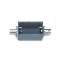


 工商网监
湘ICP备2023018690号
工商网监
湘ICP备2023018690号

