ELECTRONICS
Positive
Thermal
Coefficent
RL60 Series
Circuit Protection
System
Specifications are subject to change without notice.
Please refer to http://www.ruilon.com.cn for current information.
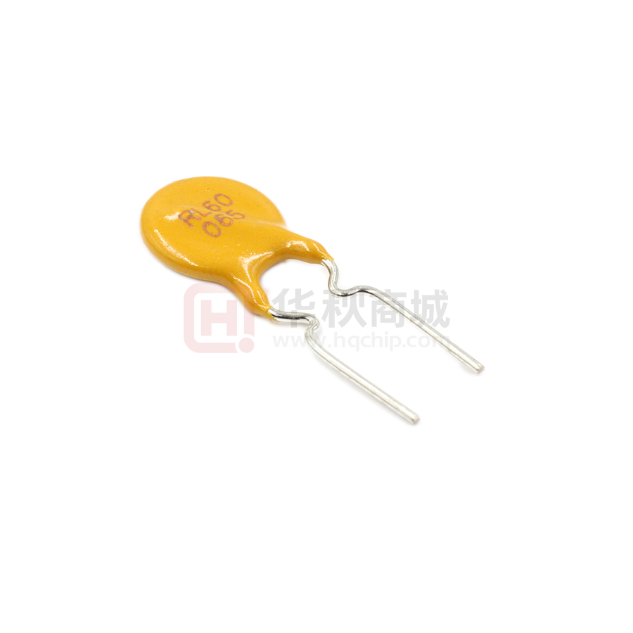
�Positive Thermal Coefficent - RL60 Series
Positive Thermal Coefficient devices(PTC),provide over-current protection
for electrical and electronic devices.They function using conducting strips
of metal imbedded inside polymers.Under normal conditions,the devices
resistance is near zero,but over-current conditions will heat the PTC and
expand the polymer,increasing the impedance.When current returns to
normal,the components cool down,returning to their original shape and very
low levels of resistance.
Features
Applications
• I(hold): 0.05~5A
• Overcurrent and overtemperature protection of automotive
• 60V Operating voltages
electronics
• Radial leaded devices
• Hard disk drives
• Over-current protection
• PC motherboards
• Very high voltage surge capabilities.
• Point-of-sale (POS) equipment
• Available in lead-free version.
• PCMCIA cards
• Fast time–to–trip
• USB port protection - USB 2.0, 3.0 & OTG
• RoHS compliant, Lead- Free and Halogen-Free
• HDMI 1.4 Source protection
• Computers & peripherals
• Industrial control
• Security systems
Product Name
R
L
LOGO
X
X
X
Voltage rating(VDC)
Circuit Protection
System
-
X
X
X
Hold current
Specifications are subject to change without notice.
Please refer to http://www.ruilon.com.cn for current information. Page:1
�Positive Thermal Coefficent - RL60 Series
E
Lead style code
A
Fig.1
D
D
A
B
Fig.2
code
A
A
E
D
A
D
B
B
B
B
Dimensions
(mm)
E
E
C
C
C
D
A
B
B
E
E
E
D
A
E
C
C
E
C
C
D
Ihold
IT
Vmax
A
A
V
Itrip A
Tmax S
RL60-005
0.05
0.1
60
0.15
RL60-010
B
0.1
E 0.2
60
RL60-017
0.17
0.34
RL60-020
0.2
0.4
Type Number
D
A
E
RL60-025
C
D
•
•
•
•
•
•
•
0.25
0.5
Time-to-Trip
Imax
Rmax
Package Dimensions
(mm)
Rmin
AA
Ω
A
Ω D
(max)
10
40
25
8
6
0.3
10
40
7.5
3.5
6
60
0.51
10
40
5.21
2.84
7
60
0.6
10
40
3.1
1.83
40
1.95
60
0.75
10
E
B
B
C
D
E
(max) (max) (max) (max)
Circuit
Figure
8.5
5.1
3.1
0.5
Fig.1
8.5
5.1
3.1
0.5
Fig.1
8.5
5.1
3.1
0.5
Fig.1
7
8.5
5.1
3.1
0.5
Fig.1
1
7.5
8.5
5.1
3.1
0.5
Fig.1
E
RL60-030
0.3
0.6
60
0.9
12
40 C
1.5
0.7
6.7
15.7
5.1
3.1
0.5
Fig.1
RL60-040
0.4
0.8
60
1.2
12
40
1.2
0.5
7.2
14.2
5.1
3.1
0.5
Fig.1
RL60-050
0.5
1
60
1.5
12
40
0.85
0.35
7.5
14.5
5.1
3.1
0.5
Fig.1
RL60-065
0.65
1.3
60
1.95
12
40
0.6A
0.25
9.1
16.1
5.1
3.1
0.5
Fig.1
RL60-075
0.75
1.5
60
2.25
12
40
0.6
0.25
9.8
16.8
5.1
3.1
0.6
Fig.1
RL60-090
0.9
1.8
60
2.7
12
40
0.45
0.18
11.7
18
5.1
3.1
0.6
Fig.1
RL60-110
1.1
2.2
60
3.3
15
40
0.38
0.15
12.5
18.5
5.1
3.1
0.8
Fig.2
RL60-135
1.35C
2.7
60
4.05
15
D40
0.31
0.12
14.5C
19.6
5.1
3.1
0.8
Fig.2
RL60-160
1.6
3.2
60
4.8
15
40
0.22
0.09
16.3
21.3
5.1
3.1
0.8
Fig.2
RL60-185
1.85
3.7
60
5.55
15
40
0.19
0.08
17.8
22.9
5.1
3.1
0.8
Fig.2
RL60-250
2.5
5
60
7.5
20
40
0.13
0.05
21.3
26.4
10.5
3.1
0.8
Fig.2
RL60-300
3
6
60
9
20
40
0.10
0.04
24.8
29.8
10.5
3.1
0.8
Fig.2
RL60-375
3.75
7.5
60
11.25
20
40
0.08
0.03
27.0
32
10.5
3.1
0.8
Fig.2
RL60-500
5
10
60
15
25
40
0.03
0.02
28.5
33.5
10.5
3.1
0.8
Fig.2
A
B
D
B
IH = Hold current: maximum current device will pass without tripping in 25℃ still air.
IT = Trip current: minimum current at which the device will trip in 25℃ still air.
VMAX = Maximum voltage device can withstand without damage at rated current.
IMAX = Maximum fault current device can withstand without damage at rated voltage.
RMAX = Maximum resistance of device in initial (un-soldered) state.
RMIN = Minimum resistance of device in initial (un-soldered) state.
Pd typ. = Typical power dissipation from device when in the tripped state at 25℃ still air
Circuit Protection
System
Specifications are subject to change without notice.
Please refer to http://www.ruilon.com.cn for current information.
Page:2
�Positive Thermal Coefficent - RL60 Series
Ihold Versus Temperature
Type Number
-40°C
-20°C
0°C
25°C
40°C
50°C
60°C
70°C
85°C
RL60-005
RL60-010
RL60-017
RL60-020
RL60-025
RL60-030
RL60-040
RL60-050
RL60-065
RL60-075
RL60-090
RL60-110
RL60-135
RL60-160
RL60-185
RL60-250
RL60-300
RL60-375
RL60-500
0.07
0.16
0.26
0.31
0.39
0.47
0.62
0.78
1.01
1.16
1.40
1.71
2.09
2.48
2.87
3.88
4.65
5.81
7.40
0.06
0.14
0.23
0.27
0.34
0.41
0.54
0.68
0.88
1.02
1.22
1.50
1.84
2.18
2.52
3.40
4.08
5.10
6.60
0.05
0.12
0.20
0.24
0.30
0.36
0.48
0.60
0.77
0.89
1.07
1.31
1.61
1.90
2.20
2.98
3.57
4.46
6.00
0.05
0.10
0.17
0.20
0.25
0.30
0.40
0.50
0.65
0.75
0.90
1.10
1.35
1.60
1.85
2.50
3.00
3.75
5.00
0.04
0.08
0.14
0.16
0.20
0.24
0.32
0.41
0.53
0.61
0.73
0.89
1.09
1.30
1.50
2.03
2.43
3.04
4.40
0.04
0.07
0.12
0.14
0.18
0.22
0.29
0.36
0.47
0.54
0.65
0.79
0.97
1.15
1.33
1.80
2.16
2.70
4.00
0.03
0.06
0.11
0.13
0.16
0.19
0.25
0.32
0.41
0.47
0.57
0.69
0.85
1.01
1.17
1.58
1.89
2.36
3.55
0.03
0.05
0.09
0.11
0.14
0.16
0.22
0.27
0.35
0.41
0.49
0.59
0.73
0.86
1.00
1.35
1.62
2.03
3.05
0.02
0.04
0.07
0.08
0.10
0.12
0.16
0.20
0.26
0.30
0.36
0.44
0.54
0.64
0.74
1.00
1.20
1.50
2.60
Temperature Rerating Curve
0.10A
0.17A
0.20A
0.25A
0.30A
0.40A
0.50A
0.65A
0.75A
0.90A
1.10A
1.35A
1.60A
1.85A
2.50A
3.00A
3.75A
Average Time Current Curves
60R
100
Time in Seconds
10
Percentage of Rated Current
170%
150%
130%
110%
90%
70%
50%
30%
10%
1
-40 -30 -20
-10
0
10
20 30
40 50
Temperature (°C)
60
70
80
0.1
0.01
0.1
1
10
100
Current in Amperes
The average time current curves and Temperature Rerating curve performance is affected
by a number or variables, and these curves provided as guidance only. Customer must
verify the performance in their application.
Circuit Protection
System
Specifications are subject to change without notice.
Please refer to http://www.ruilon.com.cn for current information. Page:3
�Positive Thermal Coefficent - RL60 Series
Manual Soldering Recommendation Parameters
Items
Conditions
Soldering condition
The highest power of the manual soldering iron should be 30W or less, soldering temperature
should not be higher than 280℃ .
Soldering time
The soldering time should be kept within 3 seconds, otherwise it might cause insulation layer
cracking, and increased part resistance.
Soldering position
The distance on the leads between the soldering point and bottom of the PPTC body should be
equal or greater than 4mm.
Other
The soldering iron should not contact the PPTC body except the leads. If the soldering
conditions are kept to lower temperature, less time and larger distance, the outcome of the
soldering will be better.
Notes: 1. Before using the device must be stored in the original bags, if the storage conditions do not guarantee, the device may
not be able to meet the given value.
2. The devices can’t used for reflow soldering.
Mechanical Characteristics
Items
Specifications
Test Conditions/Methods
Tensile strength
No visible damage
1.0Kgf, 10 seconds
Bending strength
No visible damage
0.5Kgf, 90°, 3 times
Vibration
No visible damage
Freq: 10-55Hz, Amp: 0.75mm, 1min
Mechanical Characteristics
Items
Specifications
Test Conditions/Methods
Solder ability
No visible damage,Solder OK, Solder 245±5 ℃ , 2±1s, dipping depth=0.5inch
area ≥95%
max from the body
Resistance to
soldering heat
No visible damage, Electrical OK,
│△ R/R0 │≦ 50%
260±5℃ , 10+2/-0s
Damp heat,
steady state
No visible damage, Electrical OK,
│△ R/R0 │≦ 20%
40±2℃ , 90~95 % RH, total 48Hrs, after
4Hrs test electrical parameter
Temperature
cycling
No visible damage, Electrical OK,
│△ R/R0 │≦ 20%
Ta = -10+0/-1℃ 30min, Ta = 70+1/- 0℃
30min, 5cycles, after 1hr test electrical
parameter
Circuit Protection
System
Specifications are subject to change without notice.
Please refer to http://www.ruilon.com.cn for current information.
Page:4
�Positive Thermal Coefficent - RL60 Series
Packaging
RL60-250
~
RL60-300
RL60-375
~
RL60-500
Circuit Protection
System
200pcs/bag
Specifications are subject to change without notice.
Please refer to http://www.ruilon.com.cn for current information. Page:5
�RuiLongYuan Electronics Co., Ltd.
· Reproducing and modifying information of the document is prohibited without permission from
Ruilongyuan International Inc.
· Ruilongyuan International Inc. reserves the rights to make changes of the content herein the document anytime
without notification. Please refer to our website for the latest document.
· Ruilongyuan International Inc. disclaims any and all liability arising out of the application or use of any product
including damages incidentally and consequentially occurred.
· Ruilongyuan International Inc. does not assume any and all implied warranties, including warranties of fitness
for particular purpose, non-infringement and merchantability.
· Applications shown on the herein document are examples of standard use and operation. Customers are responsible
in comprehending the suitable use in particular applications.Ruilongyuan International Inc. makes no representation or
warranty that such applications will be suitable for the specifed use without further testing or modifcation.
· The products shown herein are not designed and authorized for equipments requiring high level of reliability or relating to
human life and for any applications concerning life-saving or life-sustaining, such as medical instruments, transportation
equipment,aerospace machinery et cetera. Customers using or selling these products for use in such applications do so at
their own risk and agree to fullyindemnify Ruilongyuan International Inc. for any damages resulting from such improper use or
sale.
Tel: +86-755-8290 8296
Circuit Protection
System
Fax: +86-755-8290 8002
E-mail: jack@ruilon.com
Specifications are subject to change without notice.
Please refer to http://www.ruilon.com.cn for current information.
Page:6
�
很抱歉,暂时无法提供与“RL60-065”相匹配的价格&库存,您可以联系我们找货
免费人工找货- 国内价格
- 5+0.52686
- 50+0.43614
- 150+0.39078
- 1000+0.30800
- 2000+0.28078
- 5000+0.26717
- 国内价格
- 1+0.27000
- 10+0.26000
- 100+0.23600
- 500+0.22400


 工商网监
湘ICP备2023018690号
工商网监
湘ICP备2023018690号
