ET
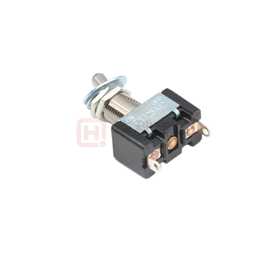
Standard Size Toggle Switch
ET
RoHS RoHS Compliant
■ Introduction
The ET series is Copal’s standard size high capacity
toggle switch. The ET series are available in various
current rating, switching functions, and terminals. The
housing is made of self-extinguishing phenol resin
which has excellent heat resistance, arc resistance,
and tracking resistance. The contacts are designed to
eliminate chattering and bouncing to prevent insulation
deterioration.
■ Part Numbering
E
T
Series code
Fig.
1
2
3
4
6
2
Actuator shape No. of poles
Current
Swiching function
Terminal styles
AC125V
AC250V
-
15
15A
10A
3A
20
20A
12A
6A
(2A)
25
25A
15A
10A
(7A)
30
30A
(25A)
Fig.
1pole
03
3A
05
5A
06
10
Fig.
K
Fig.
No. of poles
2poles
3poles
4poles
6poles
12 - Z
25
AC125V AC250V
Terminal style
None
TAB#250
10
Screw Terminal
12
Solder Terminal
13
Plate Connect SolderTerminal
1pole
3pole
2pole
4pole
6pole
A
C
D・V
E
F
G
H
-
K
M
N
P
R
S
-
PA
Key way
ON
OFF
ON
ON
ON
(ON)
ON
ON
■Terminal Style and Dimentions
TAB#250
(Style:-)
Solder Terminal
Screw Terminal
(Style:10)
M3.5×0.6
M4×0.7
M4.5×0.75
ET115・215Type
ET120・220Type
ET125・225・230Type
and
(ON)
(OFF)
:Momentary.
Please refer to P.564 for Common Specifications
Solder Terminal
(Style:12・13)
Style:12
ET103□12
Type
ET206 □12
Key way
-
-
-
OFF
-
OFF
OFF
ON
Key way
OFF
(ON)
ON
ON
(ON)
(ON)
(ON)
OFF
�ET Series Selection Table
Part No.
Appearance
No. of
poles
Rating
Switching function
Terminal style
Page
Solder Terminal
ET103
1
AC125V
3A
ON
ON
−
−
OFF
ON
416
Solder Terminal
ET105
416
1
AC125V
AC250V
ET205
5A
3A
ON
ON
ON
−
−
− OFF −
OFF
ON
ON
418
2
TAB # 250
ET110
1
ET210
2
AC125V 10A
AC250V 7A
AC125V 10A
ET115
ON
ON
ON
ON
ON
ON
−
OFF
−
ON
− OFF − ON
−
(ON)
− OFF − (ON)
− ON −
417
Screw Terminal(M3.5×0.6)
419
OFF
417
1
Solder Terminal
ET215
2
ET315
3
OFF
ON
−
OFF
−
(ON)
ON
−
ON
AC125V 15A
ON
− OFF − ON
AC250V 10A
ON
−
(ON) Solder Terminal
(ON) − OFF − (ON)
− OFF − (ON)
ON
419
421
ET415
4
TAB # 250
ET120
1
AC125V 20A
AC250V 12A
ON
ON
−
−
OFF
ON
417
Screw Terminal(M4.5×0.6)
ET125
418
1
AC125V 25A
AC250V 15A
ET225
2
ON
ON
ON
−
−
− OFF −
OFF
ON
ON
Solder Terminal
420
�Part No.
Appearance
No. of
poles
Rating
Switching function
Terminal style
Page
Solder Terminal
ET425
4
ET206
2
ET220
2
AC125V 25A
AC250V 15A
ON
ON
−
−
OFF
ON
AC125V
6A
ON
−
OFF
AC125V
AC250V
6A
2A
AC125V 20A
AC250V 12A
ON
−
424
Solder Terminal
418
ON
ON
−
OFF
ON
−
ON
(ON) − OFF − (ON)
Solder Terminal
420
Screw Terminal(M4.5×0.75)
ET230
420
2
AC125V 30A
AC250V 25A
ET330
3
ET310
3
−
−
− OFF −
OFF
ON
ON
Solder Terminal
422
Solder Terminal
AC125V 10A
AC250V 7A
ET410
ON
ON
ON
ON
ON
ON
−
−
− OFF −
OFF
ON
ON
422
4
ET420
Solder Terminal
4
421
AC125V 20A
AC250V 12A
ON
−
423
ON
ET420
Plate type
424
ET610N
Plate type
6
AC125V 10A
AC250V 7A
ON
−
ON
424
ET620N
Plate type
6
AC125V 20A
AC250V 12A
ON
−
ON
425
● Ratings are based on resistance load.
● Refer to P.425 for UL-recognized and CSA, PSE-certified products.
and
(ON)
(OFF)
:Momentary.
�ET
■Panel Cut-Out Dimensions
●Refer to P.426 for a list of accessories.
Panel thickness : 5.5mm max.
With Locking Ring
Note : Panel thickness should be 5.5 mm max. unless otherwise
specified.
Without Locking Ring
ET103□12(1 pole)
Switching
function
Key way
Key way
Key way
M12×1
Part No.
(1)(4)
ET103A12−Z
ON
−
OFF
(3)(6)
Connecting terminals
1−4
−
−
ON
−
ON
1−4
−
3−6
★ ET103V12−Z
Connecting terminals
Terminal numbers are shown on the bottom of the switch.
■Specifications
Rating
Initial contact
resistance
Dielectric
strength
ET103A12
30mΩ Max.
AC1500V
AC125V 3A
(DC2V 100mA) 1minute
ET103V12
ET105□12(1 pole)
Insulation
resistance
Electrical
life
100MΩ Min.
(DC500V)
10,000回
cycles
Terminal pins No.3 and No.6 are not available in switches with
Switching Function “A”.
L dimensions
Terminal pin No.2 is not available in switches with Switching Function “A”.
(1)
M12×1
Part No.
ET105A12−Z
ET105D12−Z
ET105E12−Z
(2)
(3)
Switching
function
Terminal numbers are shown on the bottom of the switch.
■Specifications
Rating
Terminal
style
Solder Terminal
24.6±1
24.6±1
24.6±1
Key way
Key way
ON
−
1−3
−
−
ON
ON
−
OFF
ON
ON
2−3
−
2−1
Key way
Part No.
☆ ET105A12−Z
Initial contact
resistance
Dielectric
strength
ET105A12
AC125V 5A 20mΩ Max.
AC1500V
ET105D12
AC250V 3A (DC2V 100mA) 1minute
ET105E12
Insulation
resistance
100MΩ Min.
(DC500V)
Electrical
life
20,000回
cycles
Connecting terminals
☆ ET105D12−Z
☆ ET105E12−Z
Connecting terminals
☆:Semi-standard products.
OFF
★:Made to order products.
�ET
ET110(1 pole)
Terminal pin No.2 is not available in switches with Switching
Function “A”.
L dimensions
Part No.
M12×1
ET110A■・D■−Z
ET110E■−Z
ET110F■−Z
ET110H■−Z
0.5
1
2
29
Terminal
style
TAB#250
−
−
27.6±1
27.6±1
ScrewTerminal Solder Terminal
−
−
−
25.4±1
24.6±1
24.6±1
24.6±1
24.6±1
3
Switching
function
0.5
■Specifications
ET110A■
ET110D■
ET110E■
ET110F ■
ET110H■
Initial contact
resistance
Dielectric
strength
AC125V 10A
AC250V 7A 20mΩ Max.
AC1500V
AC125V 10A(DC2V 100mA) 1minute
Insulation
resistance
Electrical
life
30,000
cycles
100MΩ Min.
(DC500V)
20,000
cycles
AC250V 7A
ET115(1 pole)
Terminal pin No.2 is not available in switches with
Switching Function “A”, “B”, or “ ”.
ET110A■−Z
ON
−
OFF
1−3
−
−
ET110D■−Z
ET110E■−Z
ET110F■−Z
ET110H■−Z
ON
ON
ON
ON
−
OFF
−
OFF
ON
ON
(ON)
(ON)
Connecting terminals
2−3
−
2−1
■:Refer to “Table of Part Numbers” on P.425 for a full list of part numbers.
L dimensions
Terminal
style
29
0.5
ET115A■・D■−Z
ET115E■−Z
ET115C■・F∼H■−Z
Switching
function
0.5
Terminal numbers are shown on the bottom of the switch.
■Specifications
ET115A■
ET115D■
ET115E■
ET115C■
ET115G■
ET115H■
Initial contact
resistance
Dielectric
strength
AC125V 15A
AC250V 10A 20mΩ Max.
AC1500V
AC125V 15A(DC2V 100mA) 1minute
Insulation
resistance
Electrical
life
30,000
cycles
100MΩ Min.
(DC500V)
20,000
cycles
AC250V 10A
ET120( pole)
Key way
Connecting terminals
Part No.
Rating
Key way
Part No.
Terminal numbers are shown on the bottom of the switch.
Rating
Key way
Terminal pin No.2 is not available in switches with
Switching Function “A”.
TAB#250
±1
27.6
27.6±1
−
ScrewTerminal Solder Terminal
25.4±1
25.4±1
25.4±1
Key way
Key way
24.6±1
24.6±1
24.6±1
Key way
Part No.
ET115A■−Z
ON
−
OFF
Connecting terminals
1−3
−
−
ET115C■−Z
OFF
−
(ON)
Connecting terminals
−
−
1−3
ET115D■−Z
ET115E■−Z
ET115G■−Z
ET115H■−Z
ON
ON
(ON)
ON
−
OFF
OFF
OFF
ON
ON
(ON)
(ON)
Connecting terminals
2−3
−
2−1
■:Refer to “Table of Part Numbers” on P.425 for a full list of part numbers.
L dimensions
Part No.
Terminal
style
ET120A■・D■−Z
TAB#250
ScrewTerminal Solder Terminal
24.6±1
−
Key way
Key way
ET120A■−Z
ON
−
OFF
Connecting terminals
1−3
−
−
ET120D■−Z
ON
−
ON
Connecting terminals
2−3
−
2−1
0.5
−
Key way
29
Switching
function
Part No.
0.5
Terminal numbers are shown on the bottom of the switch.
■Specifications
Rating
ET120A■
ET120D■
Initial contact
resistance
Dielectric
strength
AC125V 20A 20mΩ Max.
AC1500V
AC250V 12A (DC2V 100mA) 1minute
(ON)
:Momentary.
Insulation
resistance
Electrical
life
100MΩ Min.
(DC500V)
20,000
cycles
■ shows the terminal style “(blank)”, “10”, or “12”.
■:Refer to “Table of Part Numbers” on P.425 for a full list of part numbers.
�ET
ET125(1 pole)
Terminal pin No.2 is not available in switches with Switching
Function “A”.
L dimensions
Part No.
Terminal
style
ET125A■−Z
ET125D■−Z
27.6±1
ScrewTerminal Solder Terminal
28.8±1
24.6±1
0.5
M12×1
TAB#250
Key way
ET125A■−Z
ON
−
Connecting terminals
1−3
−
−
ET125D■−Z
ON
−
ON
Connecting terminals
2−3
−
2−1
29
Key way
Switching
function
Key way
Part No.
0.5
Terminal numbers are shown on the bottom of the switch.
■Specifications
Rating
ET125A■
ET125D■
OFF
■:Refer to “Table of Part Numbers” on P.425 for a full list of part numbers.
Initial contact
resistance
Dielectric
strength
AC125V 25A 20mΩ Max.
AC1500V
AC250V 15A (DC2V 100mA) 1minute
ET205(2 poles)
Insulation
resistance
Electrical
life
100MΩ Min.
(DC500V)
20,000
cycles
Terminal pins No.2 and No.5 are not available in switches with
Switching Function “K”.
Key way
Key way
ON
−
1−3 4−6
−
−
ON
ON
−
OFF
ON
ON
2−3 5−6
−
2−1 5−4
Switching
function
Key way
Part No.
★ ET205K12−Z
24
0.5
Connecting terminals
★ ET205N12−Z
★ ET205P12−Z
0.5
Connecting terminals
OFF
Terminal numbers are shown on the bottom of the switch.
■Specifications
Rating
Initial contact
resistance
Dielectric
strength
ET205K12
AC125V 5A 20mΩ Max.
AC1500V
ET205N12
AC250V 3A (DC2V 100mA) 1minute
ET205P12
ET206□12(2 poles)
Insulation
resistance
Electrical
life
100MΩ Min.
(DC500V)
20,000
cycles
Terminal pins No.3 and No.6 are not available in switches
with Switching Function “K”.
Switching
function
Key way
Key way
Key way
Part No.
M12×1
★ ET206K12−Z
Connecting terminals
ON
−
OFF
2−1 5−4
−
−
ON
−
ON
2−1 5−4
−
2−3 5−6
★ ET206N12−Z
Connecting terminals
Terminal numbers are shown on the bottom of the switch.
■Specifications
Rating
ET206K12 AC125V 6A
Initial contact
resistance
Dielectric
strength
AC1500V
20mΩ Max.
100mA)
1minute
(DC2V
AC125V 6A
ET206N12
AC250V 2A
Insulation
resistance
Electrical
life
100MΩ Min.
(DC500V)
10,000
cycles
■ shows the terminal style “(blank)”, “10”, or “12”.
☆:Semi-standard products.
★:Made to order products.
�ET
ET210(2 poles)
Terminal pins No.2 and No.5 are not available in switches
with Switching Function “K”.
L dimensions
Part No.
Terminal
style
ET210K■・N■−Z
ET210P■−Z
ET210PA −Z
30.6±1
30.6±1
−
ScrewTerminal Solder Terminal
28.4±1
28.4±1
−
27.6±1
27.6±1
27.6±1
24
0.5
M12×1
TAB#250
Switching
function
Key way
Key way
Key way
Part No.
0.5
Terminal numbers are shown on the bottom of the switch.
■Specifications
Rating
Initial contact
resistance
Dielectric
strength
ET210K■
ET210N■
ET210P■
AC125V 10A
AC250V 7A 20mΩ Max.
AC1500V
(DC2V 100mA) 1minute
ET210PA12 AC125V 10A
ET215(2 poles)
Insulation
resistance
ON
−
OFF
1−3 4−6
−
−
ET210N■−Z
ET210P■−Z
ON
ON
−
OFF
ON
ON
Connecting terminals
2−3 5−6
−
2−1 5−4
ON
ON
OFF
2−3 5−6
5−6
−
★ ET210PA12−Z
Electrical
life
Connecting terminals
■:Refer to “Table of Part Numbers” on P.425 for a full list of
part numbers.of part numbers.
30,000
cycles
100MΩ Min.
(DC500V)
ET210K■−Z
Connecting terminals
20,000
cycles
Terminal pins No.2 and No.5 are not available in switches with
Switching Function “K”, “L”, or “M”.
L dimensions
Part No.
Terminal
style
24
0.5
ET215K■・N■−Z
ET215P■−Z
ET215M·R·S ■−Z
Switching
function
TAB#250
30.6±1
30.6±1
−
ScrewTerminal Solder Terminal
28.4±1
28.4±1
28.4±1
Key way
Key way
27.6±1
27.6±1
27.6±1
Key way
Part No.
0.5
Terminal numbers are shown on the bottom of the switch.
■Specifications
Rating
ET215K■
ET215N■
ET215P ■
ET215M■
ET215R■
ET215S■
AC125V 15A
AC250V 10A
Initial contact
resistance
Dielectric
strength
20mΩ Max.
AC1500V
100mA)
1minute
(DC2V
AC125V 15A
AC250V 10A
and
(ON)
(OFF)
:Momentary.
Insulation
resistance
100MΩ Min.
(DC500V)
Electrical
life
30,000
cycles
20,000
cycles
■ shows the terminal style “(blank)”, “10”, or “12”.
ET215K■−Z
ON
−
OFF
Connecting terminals
1−3 4−6
−
−
ET215M■−Z
OFF
−
(ON)
Connecting terminals
−
−
1−3 4−6
ET215N■−Z
ET215P■−Z
ET215R■−Z
ET215S■−Z
ON
ON
ON
(ON)
−
OFF
−
OFF
ON
ON
(ON)
(ON)
Connecting terminals
2−3 5−6
−
2−1 5−4
■:Refer to “Table of Part Numbers” on P.425 for a full list of
part numbers.of part numbers.
�ET
ET220(2 poles)
Terminal pins No.2 and No.5 are not available in switches with
Switching Function “K”, “L”, or “M”.
L dimensions
Part No.
Terminal
style
ET220K■・N■−Z
ET220S−Z
M12×1
TAB#250
−
30.6±1
ScrewTerminal Solder Terminal
−
31.8±1
27.6±1
27.6±1
Key way
Key way
ET220K■−Z
ON
−
Connecting terminals
1−3 4−6
−
−
ET220N■−Z
ET220S■−Z
ON
(ON)
−
OFF
ON
(ON)
Connecting terminals
2−3 5−6
−
2−1 5−4
Switching
function
Key way
Part No.
L
Terminal numbers are shown on the bottom of the switch.
■Specifications
Rating
ET220K■
ET220N■
ET220S■
Initial contact
resistance
Dielectric
strength
AC125V 20A
AC250V 12A
AC1500V
20mΩMax.
100mA)
1minute
(DC2V
AC125V 20A
AC250V 12A
ET225(2 poles)
Insulation
resistance
Electrical
life
100MΩ Min.
(DC500V)
20,000
cycles
Terminal pins No.2 and No.5 are not available in switches
with Switching Function “K”.
OFF
■:Refer to “Table of Part Numbers” on P.425 for a full list of
part numbers.
L dimensions
Part No.
Terminal
style
ET225K■・N■−Z
ET225P■−Z
TAB#250
30.6±1
ScrewTerminal Solder Terminal
31.8±1
27.6±1
Key way
Key way
ET225K■−Z
ON
−
OFF
Connecting terminals
1−3 4−6
−
−
ET225N■−Z
ET225P■−Z
ON
ON
−
OFF
ON
ON
Connecting terminals
2−3 5−6
−
2−1 5−4
Switching
function
Key way
Part No.
Terminal numbers are shown on the bottom of the switch.
■Specifications
Rating
ET225K■
ET225N■
ET225P■
Initial contact
resistance
Dielectric
strength
AC125V 25A 20mΩ Max.
AC1500V
AC250V 15A (DC2V 100mA) 1minute
ET230(2 poles)
Insulation
resistance
Electrical
life
100MΩ Min.
(DC500V)
20,000
cycles
■:Refer to “Table of Part Numbers” on P.425 for a full list of
part numbers.
Terminal pins No.2 and No.5 are not available in switches
with Switching Function “K”.
Switching
function
Key way
Key way
Key way
Part No.
★ ET230N■−Z
★ ET230P■−Z
M12×1
Connecting terminals
ON
ON
−
OFF
ON
ON
2−3 5−6
−
2−1 5−4
Terminal numbers are shown on the bottom of the switch.
■Specifications
Rating
Initial contact
resistance
Dielectric
strength
AC1500V
ET230N10 AC250V 25A 20mΩMax.
ET230P10 AC125V 30A (DC2V 100mA) 1minute
(ON)
:Momentary.
Insulation
resistance
Electrical
life
100MΩ Min.
(DC500V)
20,000
cycles
■ shows the terminal style “(blank)”, “10”, or “12”.
★:Made to order products.
�ET
ET310(3 poles)
Terminal pins No.2, No.5, and No.8 are not available in
switches with Switching Function “A”.
L寸法/L dimensions
Part No.
ET310A■−Z
ET310D■−Z
ET310E■−Z
M12×1
Part No.
■Specifications
ET310A■
ET310D■
ET310E■
Initial contact
resistance
Dielectric
strength
AC125V 10A 20mΩ Max.
AC1500V
AC250V 7A (DC2V 100mA) 1minute
ET315□12(3 poles)
Switching
function
Insulation
resistance
Electrical
life
100MΩ Min.
(DC500V)
20,000
cycles
Switching
function
★ET315D12−Z
★ET315E12−Z
■Specifications
Dielectric
strength
AC1500V
ET315D12 AC125V 15A 20mΩ Max.
ET315E12 AC250V 10A (DC2V 100mA) 1minute
★:Made to order products.
(ON)
:Momentary.
Key way
Key way
ON
ON
2−3 5−6
Connecting terminals
8−9
Terminal numbers are shown on the bottom of the switch.
Initial contact
resistance
36.4±1
Insulation
resistance
Electrical
life
100MΩ Min.
(DC500V)
20,000
cycles
−
Key way
29.1±1
Key way
−
OFF
−
−
−
OFF
−
ON
ON
2−1 5−4
8−7
■:Refer to “Table of Part Numbers” on P.425 for a full list of
part numbers.
Terminal pins No.2, No.5, and No.8 are not available in
switches with Switching Function “A”.
M12×1
ScrewTerminal Solder Terminal
34±2
ON
1−3 4−6
Connecting terminals
7−9
ET310D■−Z
ON
ET310E■−Z
ON
2−3 5−6
Connecting terminals
8−9
Part No.
Rating
TAB#250
ET310A■−Z
Terminal numbers are shown on the bottom of the switch.
Rating
Terminal
style
■ shows the terminal style “(blank)” or “12”.
Key way
−
OFF
−
Key way
ON
ON
2−1 5−4
8−7
�ET
ET330□12(3 poles)
Terminal pins No.2, No.5, and No.8 are not available in
switches with Switching Function “A”.
L dimensions
Part No.
Terminal
style
TAB#250
33.9±2
ET330A■−Z
ET330D12−Z
ET330E12−Z
M12×1
ScrewTerminal Solder Terminal
−
−
Key way
Switching
function
Key way
29.1±1
Key way
Part No.
ET330A■−Z
Terminal numbers are shown on the bottom of the switch.
■Specifications
Rating
Initial contact
resistance
Dielectric
strength
ET330A■
AC125V 30A 20mΩMax.
AC1500V
ET330D12
AC250V 25A (DC2V 100mA) 1minute
ET330E12
Insulation
resistance
Electrical
life
100MΩ Min.
(DC500V)
20,000
cycles
ON
1−3 4−6
Connecting terminals
7−9
ON
☆ET330D12−Z
ON
★ET330E12−Z
2−3 5−6
Connecting terminals
8−9
−
OFF
−
−
−
OFF
−
ON
ON
2−1 5−4
8−7
■:Refer to “Table of Part Numbers” on P.425 for a full list of
part numbers.
ET410□12(4 poles)
Key way
Key way
Key way
Switching
function
Part No.
33.5
★ET410N12−Z
Connecting terminals
ON
2−3 5−6
8−9 11−12
−
−
ON
2−1 5−4
8−7 11−10
Terminal numbers are shown on the bottom of the switch.
■Specifications
Rating
ET410N12
Initial contact
resistance
Dielectric
strength
AC125V 10A 20mΩ Max.
AC1500V
AC250V 7A (DC2V 100mA) 1minute
■ shows the terminal style “(blank)”, “10”, or “12”.
Insulation
resistance
Electrical
life
100MΩ Min.
(DC500V)
20,000
cycles
(ON)
:Momentary.
☆:Semi-standard products.
★:Made to order products.
�ET
ET415□12(4 poles)
Terminal pins No.2, No.5, No.8, and No.11 are not available in
switches with Switching Function “K”.
Switching
function
Key way
Key way
Key way
Part No.
★ET415P12−Z
Connecting terminals
ON
2−3 5−6
8−9 11−12
OFF
−
ON
−1 5−4
8−7 11−10
Terminal numbers are shown on the bottom of the switch.
■Specifications
Rating
ET415P12
Initial contact
resistance
Dielectric
strength
AC125V 15A 20mΩ Max.
AC1500V
AC250V 10A (DC2V 100mA) 1minute
ET420□12(4 poles)
Insulation
resistance
Electrical
life
100MΩ Min.
(DC500V)
20,000
cycles
Terminal pins No.2, No.5, No.8, and No.11 are not available in
switches with Switching Function “K”.
Part No.
Switching
function
★ET420N12−Z
Connecting terminals
Terminal numbers are shown on the bottom of the switch.
■Specifications
Rating
ET420N12
Initial contact
resistance
Dielectric
strength
AC125V 20A 20mΩ Max.
AC1500V
AC250V 12A (DC2V 100mA) 1minute
★:Made to order products.
Insulation
resistance
Electrical
life
100MΩ Min.
(DC500V)
20,000
cycles
Key way
ON
2−3 5−6
8−9 11−12
Key way
−
−
Key way
ON
2−1 5−4
8−7 11−10
�ET
ET420□13(4 poles)
Terminal pins No.2, No.5, No.8, and No.11 are not available in
switches with Switching Function “K”.
Part No.
Switching
function
★ET420N13−Z
2-M3×0.5
Connecting terminals
Viewed from part No. and rating marking side
ON
2−3 5−6
8−9 11−12
−
−
ON
2−1 5−4
8−7 11−10
■Panel Cut-Out Dimensions
Terminal numbers are shown on the bottom of the switch.
Plate mounting type
■Specifications
Initial contact
resistance
Rating
ET420N13
Dielectric
strength
AC125V 20A 20mΩ Max.
AC1500V
AC250V 12A (DC2V 100mA) 1minute
ET425□12(4 poles)
Insulation
resistance
Electrical
life
100MΩ Min.
(DC500V)
20,000
cycles
Terminal pins No.2, No.5, No.8, and No.11 are not available in
switches with Switching Function “K”.
Switching
function
Key way
Key way
Key way
Part No.
★ET425K12−Z
ON
1−3 4−6
Connecting terminals
7−9 10−12
ON
★ET425N12−Z
2−3 5−6
Connecting terminals
8−9 11−12
12M×1
−
OFF
−
−
−
−
ON
2−1 5−4
8−7 11−10
Terminal numbers are shown on the bottom of the switch.
■Specifications
Initial contact
resistance
Rating
Dielectric
strength
AC1500V
ET425K12 AC125V 25A 20mΩ Max.
ET425N12 AC250V 15A (DC2V 100mA) 1minute
Insulation
resistance
Electrical
life
100MΩ Min.
(DC500V)
20,000
cycles
ET610N13(6 poles)
Switching Viewed from part No. and rating marking side
function
Part No.
☆ET610N13−Z
4-M3×0.5
ON
−
2−3 5−6
Connecting terminals 8−9 11−12
34.5
14−15 17−18
−
ON
2−1 5−4
8−7 11−10
14−13 17−16
■Panel Cut-Out Dimensions
Terminal numbers are shown on the bottom of the switch.
Plate mounting type
■Specifications
Rating
ET610N13
Initial contact
resistance
Dielectric
strength
AC125V 10A 20mΩ Max.
AC1500V
AC250V 7A (DC2V 100mA) 1minute
Insulation
resistance
Electrical
life
100MΩ Min.
(DC500V)
5,000
cycles
☆:Semi-standard products.
★:Made to order products.
�ET
ET620N13(6 poles)
Switching Viewed from part No. and rating marking side
function
Part No.
★ET620N13−Z
4-M3×0.5
ON
−
2−3 5−6
34.5
Connecting terminals 8−9 11−12
14−15 17−18
−
ON
2−1 5−4
8−7 11−10
14−13 17−16
■Panel Cut-Out Dimensions
Terminal numbers are shown on the bottom of the switch.
■Specifications
Rating
ET620N13
Plate mounting type
Initial contact
resistance
Dielectric
strength
AC125V 20A 20mΩ Max.
AC1500V
AC250V 12A (DC2V 100mA) 1minute
Insulation
resistance
Electrical
life
100MΩ Min.
(DC500V)
5,000
cycles
■Table of Part Numbers
Part No.
TAB terminals
Screw terminals
Solder terminals
★
ET110F−Z
★
ET110H−Z
ET115A−Z
☆
ET115A10−Z
※1.
Part No.
※1.
Part No.
※1.
Part No.
★
ET115D−Z
★
ET215N−Z
40.0
ET225P−Z
★
ET125A−Z
26.6 ☆
ET215P−Z
39.7 ★
ET330A−Z
ET215K−Z
39.3 ☆
ET225K−Z
39.4
29.4 ★
★
ET125A10−Z
☆
ET215N10−Z
★
ET230N10−Z
★
★
ET115D10−Z
ET215K10−Z
★
ET215P10−Z
★
ET230P10−Z
ET103A12−Z
21.0 ☆
ET120A12−Z
★
ET215M12−Z
★
ET315D12−Z
★
ET103V12−Z
21.0 ★
ET120D12−Z
☆
ET215N12−Z
38.1 ★
ET315E12−Z
☆
ET105A12−Z
☆
ET125A12−Z
25.9 ★
ET215P12−Z
37.8 ★
ET330A12−Z
26.0 ★
☆
ET105D12−Z
25.8 ★
ET125D12−Z
☆
ET105E12−Z
★
ET205K12−Z
ET215R12−Z
☆
ET330D12−Z
ET215S12−Z
38.4 ★
ET330E12−Z
☆
ET110A12−Z
25.8 ★
ET205N12−Z
★
ET220K12−Z
★
ET410N12−Z
☆
ET110D12−Z
★
ET205P12−Z
★
ET220N12−Z
★
ET415P12−Z
★
ET110E12−Z
ET206K12−Z
26.1 ★
ET220S12−Z
★
ET420N12−Z
ET115A12−Z
25.9 ☆
ET206N12−Z
26.3 ☆
ET225K12−Z
38.1 ★
ET420N13−Z
★
ET115C12−Z
☆
ET210K12−Z
ET225N12−Z
38.6 ★
ET425K12−Z
ET115D12−Z
25.9 ☆
ET210N12−Z
38.0
ET225P12−Z
★
ET425N12−Z
★
ET115E12−Z
25.9 ☆
ET210P12−Z
37.9 ★
ET310A12−Z
54.0 ☆
ET610N13−Z
★
ET115G12−Z
★
ET210PA12−Z
☆
ET310D12−Z
54.6 ★
★
ET115H12−Z
ET215K12−Z
37.9 ☆
ET310E12−Z
25.0 ☆
※1.
54.4
54.7
54.2
57.4
105.0
ET620N13−Z
−
−
As shown in the above table, not all products are UL-recognized or CSA-certified.Please check with your local sales representative if you have any questions.
Note: For overseas standards, see P.627.
※1 : Switch mass (g) : includes accessories = hex nut, locking ring, lock washer and terminal screw
★:Made to order products.
☆:Semi-standard products.
�ET
■ Standard Accessories
《Supplied with switch》
Part Name
Hex Nut
Hex Nut
Lockwasher
Locking Ring
Part No.
140008010235
140008010221
140008030055
140008020065
Nickel plated
Zinc plated
Zinc plated
Zinc plated
Dimensions
Finish
■Optional Accessories
ET·8B
Type
Part Name
Part No.
《Supplied separately》
Plate
140008040021
ET
Plate
140008040025
ET
Waterproof boot
Red 140000610335
Gray 140000610334
Black 140000610333
Boot
Bushing
140000610080
140008010244
Dimensions
■Handling Precautions
1. Soldering Specifications
⑴Manual Soldering
Device:Soldering iron
420℃, Max.; 3 seconds, Max.
⑵ Waterproof boot
①The boot is fixed to the switch with the built-in screw.
②The boot cannot be used for plate-mounting switches.
■Packaging Specification
ビニール袋
Plastic bag
付属部品
Accessories
2. Flux Cleaning
⑴ Solvent : Fluorine or Alcohol type.
⑵ The ET series are not washable. To wash the PC board, clean
the soldering surface of the PC board with a brush so that
the switch is not exposed to the cleaning solution.
:Optional Accessories.
�


 工商网监
湘ICP备2023018690号
工商网监
湘ICP备2023018690号

