XR2682
______________________________________ ____________________________________________________ _______________________________
3.3V~5V Input 12W Output Step-up DC/DC Converter
GENERAL DESCRIPTION
FEATURES
The XR2682 is a high frequency, high
efficiency DC to DC converter with an
integrated 6A, 40mΩ power switch capable
of providing an output voltage up to 24V.
The fixed 600KHz allows the use of small
external inductions and capacitors and
provides fast transient response. It
integrates Soft start, Comp,. only need few
components outside.
It can output 6V 2A、9V 1.3A for single
battery input. If Vbat=3.6V, it can output 6V
2.5A、9V 1.5A at good heat dissipation
condition.
2.7V to 5.5V input voltage Range
Efficiency up to 96%
24V Boost converter with 6A switch
current Limit
600KHz fixed Switching Frequency
Integrated soft-start
Thermal Shutdown
Under voltage Lockout
Upward pin-to-pin compatible XR2981
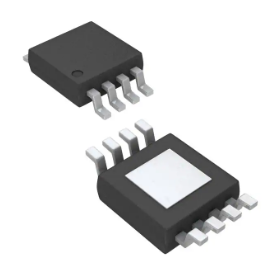
8-Pin SOP-PP Package
APPLICATIONS
Portable Audio Amplifier Power Supply
Power Bank
QC 2.0/Type C
Wireless Charger
POS Printer Power Supply
Small Motor Power Supply
L 2.2uH 6A
D
20V 3A
Vin 3.3V~4.2V
3,4
Cby
1uF
16V
Cin
220uF
6.3V
5
22uF
10V
7,8
VDD
SW
EN
FB
Vout 6V 2A
1,2
R1
38K
Cout
R2
10K
22uF
10V
6
GND/EPAD
220uF
16V
Figure 1. Typical Application Circuit1
(for Single cell Li-Battery)
Suzhou XySemi Electronic Technology Co., Limited.
-1-
www.xysemi.com.cn
Rev 0.4
�XR2682
______________________________________ ____________________________________________________ _______________________________
Figure 2. Typical Application Circuit2
(for Dual cell Li-Battery)
ORDERING INFORMATION
PART
NUMBER
TEMP RANGE
SWICHING
FREQUENCY
OUTPUT
VOLTAGE (V)
ILIM (A)
PACKAGE
PINS
XR2682
-40°C to 85°C
600KHZ
ADJ
6
SOP-PP
8
Suzhou XySemi Electronic Technology Co., Limited.
-2-
www.xysemi.com.cn
Rev0.4
�XR2682
______________________________________ ____________________________________________________ _______________________________
PIN CONFIGURATION
Figure 3. PIN Configuration
PIN DESCRIPTION
PIN
NUMBER
PIN
NAME
1,2
SW
3
PVDD
Input power supply pin, please connect with Cin close asp
4
AVDD
Boost IC Logic power supply pin,if far from Cin, please add one 1uF MLCC close asp
5
EN
Shutdown control input., Connect this pin to logic high level to enable the device
6
FB
Feedback pin
7
AGND
Analog ground
8
PGND
Power ground
EPAD
PGND
Please connect with PGND & AGND by mass metal for Low Rdson 、High efficiency &
Good heat dissipation
PIN DESCRIPTION
Switch pin
Suzhou XySemi Electronic Technology Co., Limited.
-3-
www.xysemi.com.cn
Rev0.4
�XR2682
______________________________________ ____________________________________________________ _______________________________
ABSOLUTE MAXIMUM RATINGS
(Note: Do not exceed these limits to prevent damage to the device. Exposure to absolute maximum rating
conditions for long periods may affect device reliability.)
PARAMETER
VALUE
UNIT
Supply Voltage VIN
-0.3 to 6.5
V
FB, EN Voltage
-0.3 to 6.5
V
SW Voltage
Operating Ambient Temperature
-0.3 to 26V
V
-40 to 85
°C
150
°C
-55 to 150
°C
300
°C
Maximum Junction Temperature
Storage Temperature
Lead Temperature (Soldering, 10 sec)
ELECTRICAL CHARACTERISTICS
(VIN = 3.6V, TA= 25C unless otherwise specified)
PARAMETER
Input Voltage Range
Boost output voltage range
SYMBOL
TEST CONDITIONS
MIN
VIN
2.7
Vout
24
TYP
MAX
UNIT
5.5
V
V
UVLO Low Threshold
VUVLOL
2.6
V
UVLO High Threshold
VUVLOH
3.2
V
Operating Supply Current
100
VFB =1.5V,EN=Vin, ILoad =0
ISUPPLY
Shutdown Supply Current
µA
VEN =0V, VIN =3.6V
Regulated Feedback
Voltage
VFB
Peak Inductor Current
IPEAK
Oscillator Frequency
FOSC
1.21 1.24
1.27
6
400
Rds(ON) of N-channel FET
ISW =1A
Enable Threshold
VIN = 2.7V to 5.5V
0.3
-0.1
VEN = 0V, VSW = 0V or 5V, VIN = 5V
Suzhou XySemi Electronic Technology Co., Limited.
600
-4-
1
V
A
800
40
Enable Leakage Current
SW Leakage Current
1
KHz
mΩ
1.5
V
0.1
µA
1
uA
www.xysemi.com.cn
Rev0.4
�XR2682
______________________________________ ____________________________________________________ _______________________________
Figure 4. Functional Block Diagram
FUNCTIONAL DESCRIPTION
amplifier. The control loop, determined by the error
amplifier, only has to handle small signal errors.
The input for it is the feedback voltage on the FB
pin, the voltage on the internal resistor divider. It is
compared with the internal reference voltage to
generate an accurate and stable output voltage.
NORMAL OPERATION
The boost converter is designed for output
voltage up to 24V with a 6A/24V power MOSFET.
The low Rdson of the internal power switches
enables better power efficiency. The chip, which
operates in a current mode scheme with constant
frequency 600KHz. It operates with Pulse With
Modulation(PWM). To avoid the inrush current
during power up, soft start circuit is integrated in the
chip.
CYCLE BY CYCLE CURRENT LIMIT
The peak current of the NMOS switch is also
sensed to limit the maximum current flowing
through the switch and the inductor. The typical
peak current limit is set to exceed 6A.
The controller circuit of the device is based on a
fixed frequency multiple feedback controller
topology. Input voltage, output voltage, and voltage
drop on the NMOS switch are monitored and
feedback to the regulator. So changes in the
operating conditions of the converter directly affect
the duty cycle and must not take the indirect and
slow way through the control loop and the error
Suzhou XySemi Electronic Technology Co., Limited.
UNDERVOLTAGE LOCKOUT (UVLO)
Under voltage lockout prevents operation of the
device at input voltages below typical 2.6V when
the input voltage is falling. When the input voltage is
below the under voltage threshold, the device is
-5-
www.xysemi.com.cn
Rev0.4
�XR2682
______________________________________ ____________________________________________________ _______________________________
shut down and the internal switch FETs are turned
off. If the input voltage rises by under voltage
lockout hysteresis(3.2V), the IC restarts.
damages due to excessive heat and power
dissipation. Typically the thermal shutdown
THERMAL SHUTDOWN
temperature falls below typically 136 ℃ .Then the
device starts switching again.
threshold is 150℃ .When the thermal shutdown is
triggered the device stops switching until the
A thermal shutdown is implemented to prevent
APPLICATION INFORMATION
INDUCTOR SELECTION
In normal operation, the inductor maintains continuous current to the output. The inductor current has
a ripple that is dependent on the inductance value. The high inductance reduces the ripple current.
Selected inductor by actual application:
Manufa Part Number Inductance
cturer
(uH)
TDK
WURT
H
DRC max
(Ohms)
Dimensions
L*W*H(mm3)
SPM6530T
2.2
0.017
7.1*6.5*3
CLF10040T
2.2
0.0097
10*9.7*3.8
2.2
0.012
2.2
0.012
74437349022
744311220
7.3*6.6*4.8
7.0*6.9*3.8
Table 1. Recommend Surface Mount Inductors
Notes:Please select inductor according to I in. The IL need to be 1.5~2*I in. For getting higher efficiency, need to
use low DRC inductors.
INPUT CAPACITOR SELECTION
The input capacitor reduces input voltage ripple to the converter, low ESR ceramic capacitor is highly
recommended. For audio amplifier applications, A 22uF ceramic capacitor & 220uF E-cap is needed. low ESR
tantalum capacitor is recommended for good ripple performance & dynamic response , The input capacitor
should be placed as close as possible to VIN and GND.
OUTPUT CAPACITOR SELECTION
A low ESR output capacitor is required in order to maintain low output voltage ripple. In the case of ceramic
output capacitors, capacitor ESR is very small and does not contribute to the ripple, so a lower capacitance
value is acceptable when ceramic capacitors are used. For audio amplifier applications, A 22uF ceramic
capacitor & 220uF E-cap is needed. low ESR tantalum capacitor is recommended for good ripple performance &
dynamic response .
Suzhou XySemi Electronic Technology Co., Limited.
-6-
www.xysemi.com.cn
Rev0.4
�XR2682
______________________________________ ____________________________________________________ _______________________________
OUTPUT VOLTAGE PROGRAMMING
In the adjustable version, the output voltage is set by a resistive divider according to the following equation:
Typically choose R2=10K and determine R1 from the following equation:
DIODE SELECTION
According to max Iout
and max Vout, you can select suitable diode. Normally we select
diode
If=(1.5~2)*Ioutmax and VR=(1.5~2)*Voutmax. For high efficiency,suggest that you select low Vf Schottky
diode.
For example, 3.3V~4.2Vin 6V 2Aout, you can select SS54 or MBRS410. MBRS410 for high efficiency.
LDO SELECTION
For Typical Application Circuit2, you need to select
higher) .Iout>=100mA.Output voltage is preferred to set 4.2V~4.5V.
LDO--Input
voltage
range
4V~15V(or
LDO need enough input & output capacity ,please select suitable external parts and layout them according to
LDO‘s datasheet.
Suzhou XySemi Electronic Technology Co., Limited.
-7-
www.xysemi.com.cn
Rev0.4
�XR2682
______________________________________ ____________________________________________________ _______________________________
LAYOUT CONSIDERATIONS
1:The input capacitor, output capacitor, and the inductor should be placed as close as possible to the IC. to
keep resistance very low and the switching loop very small for EMI performance
2:The FB pin connection should be made as close to the load as possible so that the voltage at the load is
the expected regulated value. and place FB network far from Switching node.
3:Please make sure that the big current circuits are board and short to reduce the circuit Rdson , All ground
connection must be tied together. Use a broad ground plane to establish the lowest resistance possible between
all connections to achieve the best thermal and noise performance.
4: The switch node connection should be low resistance to reduce power losses.
5:The heavy copper board in big current output is recommended for high efficiency & good heat dissipation.
L 2.2uH 6A
D
20V 3A
Vin 3.3V~4.2V
3,4
Cby
1uF
16V
Cin
220uF
6.3V
5
VDD
SW
Switching Loop1
22uF
10V
7,8
EN
FB
GND/EPAD
Vout 6V 2A
1,2
6
Switching
Loop2
R1
38K
Cout
R2
10K
22uF
10V
220uF
16V
PCB LAYOUT GUIDE
TOP LAYER
Suzhou XySemi Electronic Technology Co., Limited.
BOTTOM LAYER
-8-
www.xysemi.com.cn
Rev0.4
�XR2682
______________________________________ ____________________________________________________ _______________________________
TYPICAL PERFORMANCE CHARACTERISTICS
(L=2.2uH-Wurth 74437349022, Cin or Cout=22uF MLCC+220uF Ecap; D=MBRS410 ,if not
mentioned)
Note: Efficiency data is based on demo test at 20℃. If work at big current for long time,
maybe thermal shutdown. its load capacity is related with heat dissipation conditions.
3.6Vin9Vout 50mA Switching
Suzhou XySemi Electronic Technology Co., Limited.
3.6Vin9Vout 1A Switching
-9-
www.xysemi.com.cn
Rev0.4
�XR2682
______________________________________ ____________________________________________________ _______________________________
3.6Vin12Vout 50mA Switching
3.6Vin12Vout 200mA Switching
3.6Vin12Vout 1A Switching
9Vout Startup from Vin
Suzhou XySemi Electronic Technology Co., Limited.
www.xysemi.com.cn
9Vout Startup from EN
- 10 Rev0.4
�XR2682
______________________________________ ____________________________________________________ _______________________________
PACKAGE OUTLINE
SOP8-PP PACKAGE OUTLINE AND DIMENSIONS
SYMBOL
A
A1
A2
B
C
D
E
E1
e
L
F
G
Dimension in Dimension in
Millimeters
Inches
MIN
MAX
MIN
MAX
1.35
1.75 0.053 0.069
0.100 0.250 0.004 0.010
1.350 1.550 0.053 0.061
0.330 0.510 0.013 0.020
0.190 0.250 0.007 0.010
4.700 5.100 0.185 0.201
3.800 4.000 0.150 0.157
5.800 6.300 0.228 0.248
1.27 TYP
0.050 TYP
0.400 1.270 0.016 0.050
0o
8o
0o
8o
2.26
2.56 0.089 0.101
3.15
3.45 0.124 0.136
In order to increase the driver current capability of XR2682 and improve the
temperature of package, Please ensure Epad and enough ground PCB to release
energy.
Suzhou XySemi Electronic Technology Co., Limited.
www.xysemi.com.cn
- 11 Rev0.4
�


 工商网监
湘ICP备2023018690号
工商网监
湘ICP备2023018690号
