UMW
R
UMW P6SMB Series
FEATURES
•
•
•
•
•
•
•
•
•
•
SMB(DO-214AA)
Low profile package
Ideal for automated placement
Glass passivated chip junction
Available in uni-directional and bi-directional
600 W peak pulse power capability with a
10/1000 μs waveform, repetitive rate (duty
cycle): 0.01 %
Excellent clamping capability
Very fast response time
Low incremental surge resistance
Meets MSL level 1, per J-STD-020, LF maximum peak
of 260 °C
AEC-Q101 qualified available
- Automotive ordering code: base P/NHE3 or P/NHM3
Cathode Band
0.086(2.20)
0.155(3.94)
0.077(1.95)
0.130(3.30)
0.180(4.57)
0.160(4.06)
0.012(0.305)
0.006(0.152)
0.096(2.44)
0.084(2.13)
0.060(1.52)
0.030(0.76)
0.008(0.2)
0(0)
MECHANICAL DATA
0.220(5.59)
0.205(5.21)
Case: SMB (DO-214AA)
Molding compound meets UL 94 V-0 flammability rating
Base P/N-E3 - RoHS-compliant, commercial grade
Base P/N-M3 - halogen-free, RoHS-compliant, commercial
grade
Base P/NHE3_X - RoHS-compliant and AEC-Q101 qualified
Base P/NHM3_X - halogen-free, RoHS-compliant, and
AEC-Q101 qualified
(“_X” denotes revision code e.g. A, B, ..... and only available
for 250 V to 540 V type)
Terminals: matte tin plated leads, solderable per
J-STD-002 and JESD 22-B102
E3, M3, HE3, and HM3 suffix meets JESD 201 class 2
whisker test
Polarity: for uni-directional types the band denotes cathode
end, no marking on bi-directional types
Dimensions in inches and (millimeters)
MAXIMUM RATINGS (TA = 25 °C unless otherwise noted)
PARAMETER
Peak power dissipation with a 10/1000 μs waveform (1)(2) (fig. 1)
Maximum Instantaneous Forward Voltage at
50.0A for Unidirectional Only (Note 4)
Power dissipation on infinite heatsink at TA = 50 °C
Peak forward surge current 8.3 ms single half sine-wave uni-directional only (2)
Operating junction and storage temperature range
SYMBOL
VALUE
UNIT
PPPM
600
W
VF
3.5
Volts
W
PD
5.0
IFSM
100
A
TJ, TSTG
-65 to +150
°C
Notes
(1) Non-repetitive current pulse, per fig. 3 and derated above T = 25 °C per fig. 2
A
(2) Mounted on 0.2" x 0.2" (5.0 mm x 5.0 mm) copper pads to each terminal
www.umw-ic.com
1
友台半导体有限公司
�UMW
R
UMW P6SMB Series
ELECTRICAL CHARACTERISTICS (TA = 25 °C unless otherwise noted)
PART NUMBER
P6SMB6.8A(CA)
P6SMB7.5A(CA)
P6SMB8.2A(CA)
P6SMB9.1A(CA)
P6SMB10A(CA)
P6SMB11A(CA)
P6SMB12A(CA)
P6SMB13A(CA)
P6SMB15A(CA)
P6SMB16A(CA)
P6SMB18A(CA)
P6SMB20A(CA)
P6SMB22A(CA)
P6SMB24A(CA)
P6SMB27A(CA)
P6SMB30A(CA)
P6SMB33A(CA)
P6SMB36A(CA)
P6SMB39A(CA)
P6SMB43A(CA)
P6SMB47A(CA)
P6SMB51A(CA)
P6SMB56A(CA)
P6SMB62A(CA)
P6SMB68A(CA)
P6SMB75A(CA)
P6SMB82A(CA)
P6SMB91A(CA)
P6SMB100A(CA)
P6SMB110A(CA)
P6SMB120A(CA)
P6SMB130A(CA)
P6SMB150A(CA)
P6SMB160A(CA)
P6SMB170A(CA)
P6SMB180A(CA)
P6SMB200A(CA)
P6SMB220A(CA)
P6SMB250A(CA)
P6SMB300A(CA)
P6SMB350A(CA)
P6SMB400A(CA)
P6SMB440A(CA)
P6SMB480A(CA)
P6SMB510A(CA)
P6SMB540A(CA)
DEVICE
MARKING
CODE
UNI
6V8A
7V5A
8V2A
9V1A
10A
11A
12A
13A
15A
16A
18A
20A
22A
24A
27A
30A
33A
36A
39A
43A
47A
51A
56A
62A
68A
75A
82A
91A
100A
110A
120A
130A
150A
160A
170A
180A
200A
220A
250A
300A
350A
400A
440A
480A
510A
540A
BI
6V8C
7V5C
8V2C
9V1C
10C
11C
12C
13C
15C
16C
18C
20C
22C
24C
27C
30C
33C
36C
39C
43C
47C
51C
56C
62C
68C
75C
82C
91C
100C
110C
120C
130C
150C
160C
170C
180C
200C
220C
-
BREAKDOWN
VOLTAGE
VBR AT IT (1)
MIN.
6.45
7.13
7.79
8.65
9.5
10.5
11.4
12.4
14.3
15.2
17.1
19
20.9
22.8
25.7
28.5
31.4
34.2
37.1
40.9
44.7
48.5
53.2
58.9
64.6
71.3
77.9
86.5
95
105
114
124
143
152
162
171
190
209
237
285
333
380
418
456
485
513
MAX.
7.14
7.88
8.61
9.55
10.5
11.6
12.6
13.7
15.8
16.8
18.9
21
23.1
25.2
28.4
31.5
34.7
37.8
41
45.2
49.4
53.6
58.8
65.1
71.4
78.8
86.1
95.5
105
116
126
137
158
168
179
189
210
231
263
315
368
420
462
504
535
567
TEST
CURRENT
IT
(mA)
10
10
10
1
1
1
1
1
1
1
1
1
1
1
1
1
1
1
1
1
1
1
1
1
1
1
1
1
1
1
1
1
1
1
1
1
1
1
1
1
1
1
1
1
1
1
MAXIMUM
REVERSE
STAND-OFF
LEAKAGE
VOLTAGE
AT VWM
VWM (V)
ID (3)
(μA)
5.8
1000
6.4
500
7.02
200
7.78
50
8.55
10
9.4
5
10.2
5
11.1
5
12.8
1
13.6
1
15.3
1
17.1
1
18.8
1
20.5
1
23.1
1
25.6
1
28.2
1
30.8
1
33.3
1
36.8
1
40.2
1
43.6
1
47.8
1
53
1
58.1
1
64.1
1
70.1
1
77.8
1
85.5
1
94
1
102
1
111
1
128
1
136
1
145
1
154
1
171
1
185
1
214
1
256
1
300
1
342
1
376
1
408
1
434
1
459
1
MAXIMUM
PEAK
PULSE
CURRENT
IPPM (2)
(A)
57.1
53.1
49.6
44.8
41.4
38.5
35.9
33
28.3
26.7
23.8
21.7
19.6
18.1
16
14.5
13.1
12
11.1
10.1
9.3
8.6
7.8
7.1
6.5
5.8
5.3
4.8
4.4
3.9
3.6
3.4
2.9
2.7
2.6
2.4
2.2
1.8
1.74
1.45
1.24
1.1
1
0.91
0.86
0.81
MAXIMUM MAXIMUM
CLAMPING TEMPERAT
VOLTAGE
URE
AT IPPM
OF VBR
VC (V)
(%/°C)
10.5
11.3
12.1
13.4
14.5
15.6
16.7
18.2
21.2
22.5
25.2
27.7
30.6
33.2
37.5
41.4
45.7
49.9
53.9
59.3
64.8
70.1
77
85
92
103
113
125
137
152
165
179
207
219
234
246
274
328
344
414
482
548
602
658
698
740
0.057
0.061
0.065
0.068
0.073
0.075
0.078
0.081
0.084
0.086
0.088
0.09
0.092
0.094
0.096
0.097
0.098
0.099
0.1
0.101
0.101
0.102
0.103
0.104
0.104
0.105
0.105
0.106
0.106
0.107
0.107
0.107
0.108
0.108
0.108
0.108
0.108
0.108
0.11
0.11
0.11
0.11
0.11
0.11
0.11
0.11
Notes
(1) Pulse test: t ≤ 50 ms
p
(2) Surge current waveform per fig. 3 and derate per fig. 2
(3) For bi-directional types with V
WM of 10 V and less, the ID limit is doubled
(4) All terms and symbols are consistent with ANSI/IEEE CA62.35
(5) V = 3.5 V at I = 50 A (uni-directional only)
F
F
www.umw-ic.com
2
友台半导体有限公司
�R
UMW
UMW P6SMB Series
RATINGS AND CHARACTERISTICS CURVES (TA = 25 °C unless otherwise noted)
Peak Pulse Power (PPP) or Current (IPP)
Derating in Percentage, %
PPPM - Peak Pulse Power (kW)
100
10
1
0.1
0.1 µs
1.0 µs
10 µs
100 µs
1.0 ms
10 ms
50
25
0
0
25
50
75
100
125
150
175
200
TJ - Initial Temperature (°C)
Fig. 1 - Peak Pulse Power Rating Curve
Fig. 2 - Pulse Power or Current vs. Initial Junction Temperature
100
TJ = 25 °C
Pulse Width (td)
is defined as the Point
where the Peak Current
decays to 50 % of IPPM
tr = 10 µs
Peak Value
IPPM
100
Transient Thermal Impedance (°C/W)
IPPM - Peak Pulse Current, % IRSM
75
td - Pulse Width (s)
150
Half Value - IPP
IPPM
2
50
10/1000 µs Waveform
as defined by R.E.A.
td
0
1.0
2.0
3.0
10
1.0
0.1
0.001
0
4.0
0.01
0.1
1
10
100
1000
t - Time (ms)
tp - Pulse Duration (s)
Fig. 3 - Pulse Waveform
Fig. 5 - Typical Transient Thermal Impedance
200
6000
Measured at
Zero Bias
Peak Forward Surge Current (A)
CJ - Junction Capacitance (pF)
100
1000
VR, Measured at
Stand-Off Voltage VWM
100
Uni-Directional
Bi-Directional
TJ = 25 °C
f = 1.0 MHz
Vsig = 50 mVp-p
8.3 ms Single Half Sine-Wave
Uni-Directional Only
100
10
10
1
10
100
200
1
100
10
VWM - Reverse Stand-Off Voltage (V)
Number of Cycles at 60 Hz
Fig. 4 - Typical Junction Capacitance
Fig. 6 - Maximum Non-Repetitive Peak Forward Surge Current
www.umw-ic.com
3
友台半导体有限公司
�UMW
R
UMW P6SMB Series
ORDERING INFORMATION
Order Code
Package
Baseqty
Deliverymode
UMW P6SMBxxA
SMB
750
Tape and reel
UMW P6SMBxxCA
SMB
750
Tape and reel
www.umw-ic.com
4
友台半导体有限公司
�
很抱歉,暂时无法提供与“P6SMB440A”相匹配的价格&库存,您可以联系我们找货
免费人工找货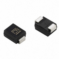


 工商网监
湘ICP备2023018690号
工商网监
湘ICP备2023018690号
