SMCJ5.0 THRU SMCJ440CA
SURFACE MOUNT TRANSIENT VOLTAGE SUPPRESSOR
Stand-off Voltage: 5.0-440 Volts
FEATURE
DO-214AB/SMC
For surface mounted applications in order to optimize board space
Low profile package
Built-in strain relief
Glass passivated junction
Low inductance
Excellent clamping capability
1500W peak pulse power capability at 10/1000μs waveform,
repetition rate (duty cycle): 0.01%
Fast response time
Typical IR less than 1μA above 10V
High Temperature soldering: 260℃/10 seconds at terminals
Plastic package has underwriters laboratory flammability 94V-0
0.245(6.22)
0.220(5.59)
0.126 (3.20)
0.114 (2.90)
0.280(7.11)
0.260(6.60)
0.012(0.305)
0.006(0.152)
0.103(2.62)
0.079(2.06)
0.060(1.52)
0.030(0.76)
Peak pulse power: 1500 Watts
MECHANICAL DATA
0.008(0.203)MAX.
Case: JEDEC DO-214AB. Molded plastic over glass passivated junction
Terminal: Solder plated, solderable per MIL-STD-750, Method 2026
Polarity: Color band denotes cathode except bi-directional models
Standard Packaging: 12mm tape (EIA STD RS-481)
0.320(8.13)
0.305(7.75)
Dimensions in inches and (millimeters)
APPLICATIONS
I/O interface
AC/DC power supply
Low frequency signal transmission line (RS232, RS485, etc.)
MAXIMUM RATINGS AND CHARACTERISTICS
Ratings at 25℃ ambient temperature unless otherwise specified.
Peak pulse power dissipation at 10/1000μs waveform
(Note1, Note2, Fig.1)
PPPM
Peak pulse current of at 10/1000μs waveform (Note 1, Fig.3)
IPPM
See Table
Amps
PM(AV)
6.5
Watts
200
Amps
Steady state power dissipation at TA=50℃ (Fig.5)
Peak forward surge current, 8.3ms single half sine-wave
superimposed on rated load, (JEDEC Method) (Note3, Fig.6)
Operating junction and Storage Temperature Range.
IFSM
Minimum 1500
Watts
TJ,TSTG
-65 to +150
℃
Typical thermal resistance junction to lead
RθJL
15
℃/W
Typical thermal resistance junction to ambient
RθJA
75
℃/W
Notes: 1. Non-repetitive current pulse, per Fig.3 and derated above TA=25℃ per Fig.2.
2. Mounted on 5.0mm×5.0mm (0.03mm thick) copper pads to each terminal.
3. 8.3ms single half sine-wave, or equivalent square wave, duty cycle=4 pulses per minutes maximum.
�Electrical Characteristics (TA=25℃
℃)
Part Number
Device
Marking
Code
Reverse
Stand-Off
Voltage
Breakdown
Voltage
@IT
Test
Current
Maximum
Clamping
Voltage
@IPP
Peak
Pulse
Current
Reverse
Leakage
@VRWM
Unidirectional
Bidirectional
UNI
BI
VRWM(V)
VBR(V)
IT(mA)
VC(V)
IPP(A)
IR(μA)
SMCJ5.0A
SMCJ5.0CA
GDE
BDE
5.0
6.40~7.00
10
9.2
163.0
800
SMCJ6.0A
SMCJ6.0CA
GDG
BDG
6.0
6.67~7.37
10
10.3
145.7
800
500
SMCJ6.5A
SMCJ6.5CA
GDK
BDK
6.5
7.22~7.98
10
11.2
134.0
SMCJ7.0A
SMCJ7.0CA
GDM
BDM
7.0
7.78~8.60
10
12.0
125.0
200
SMCJ7.5A
SMCJ7.5CA
GDP
BDP
7.5
8.33~9.21
1
12.9
116.3
100
SMCJ8.0A
SMCJ8.0CA
GDR
BDR
8.0
8.89~9.83
1
13.6
110.3
50
SMCJ8.5A
SMCJ8.5CA
GDT
BDT
8.5
9.44~10.40
1
14.4
104.2
20
SMCJ9.0A
SMCJ9.0CA
GDV
BDV
9.0
10.00~11.10
1
15.4
97.4
10
SMCJ10A
SMCJ10CA
GDX
BDX
10.0
11.10~12.30
1
17.0
88.3
5
SMCJ11A
SMCJ11CA
GDZ
BDZ
11.0
12.20~13.50
1
18.2
82.5
1
SMCJ12A
SMCJ12CA
GEE
BEE
12.0
13.30~14.70
1
19.9
75.4
1
SMCJ13A
SMCJ13CA
GEG
BEG
13.0
14.40~15.90
1
21.5
69.8
1
SMCJ14A
SMCJ14CA
GEK
BEK
14.0
15.60~17.20
1
23.2
64.7
1
SMCJ15A
SMCJ15CA
GEM
BEM
15.0
16.70~18.50
1
24.4
61.5
1
SMCJ16A
SMCJ16CA
GEP
BEP
16.0
17.80~19.70
1
26.0
57.7
1
SMCJ17A
SMCJ17CA
GER
BER
17.0
18.90~20.90
1
27.6
54.4
1
SMCJ18A
SMCJ18CA
GET
BET
18.0
20.00~22.10
1
29.2
51.4
1
SMCJ20A
SMCJ20CA
GEV
BEV
20.0
22.20~24.50
1
32.4
46.3
1
SMCJ22A
SMCJ22CA
GEX
BEX
22.0
24.40~26.90
1
35.5
42.3
1
SMCJ24A
SMCJ24CA
GEZ
BEZ
24.0
26.70~29.50
1
38.9
38.6
1
SMCJ26A
SMCJ26CA
GFE
BFE
26.0
28.90~31.90
1
42.1
35.7
1
SMCJ28A
SMCJ28CA
GFG
BFG
28.0
31.10~34.40
1
45.4
33.1
1
SMCJ30A
SMCJ30CA
GFK
BFK
30.0
33.30~36.80
1
48.4
31.0
1
SMCJ33A
SMCJ33CA
GFM
BFM
33.0
36.70~40.60
1
53.3
28.2
1
SMCJ36A
SMCJ36CA
GFP
BFP
36.0
40.00~44.20
1
58.1
25.9
1
SMCJ40A
SMCJ40CA
GFR
BFR
40.0
44.40~49.10
1
64.5
23.3
1
SMCJ43A
SMCJ43CA
GFT
BFT
43.0
47.80~52.80
1
69.4
21.7
1
SMCJ45A
SMCJ45CA
GFV
BFV
45.0
50.00~55.30
1
72.7
20.6
1
SMCJ48A
SMCJ48CA
GFX
BFX
48.0
53.30~58.90
1
77.4
19.4
1
SMCJ51A
SMCJ51CA
GFZ
BFZ
51.0
56.70~62.70
1
82.4
18.2
1
SMCJ54A
SMCJ54CA
GGE
BGE
54.0
60.00~66.30
1
87.1
17.3
1
SMCJ58A
SMCJ58CA
GGG
BGG
58.0
64.40~71.20
1
93.6
16.1
1
SMCJ60A
SMCJ60CA
GGK
BGK
60.0
66.70~73.70
1
96.8
15.5
1
SMCJ64A
SMCJ64CA
GGM
BGM
64.0
71.10~78.60
1
103.0
14.6
1
SMCJ70A
SMCJ70CA
GGP
BGP
70.0
77.80~86.00
1
113.0
13.3
1
SMCJ75A
SMCJ75CA
GGR
BGR
75.0
83.30~92.10
1
121.0
12.4
1
SMCJ78A
SMCJ78CA
GGT
BGT
78.0
86.70~95.80
1
126.0
11.9
1
SMCJ85A
SMCJ85CA
GGV
BGV
85.0
94.40~104.00
1
137.0
11.0
1
SMCJ90A
SMCJ90CA
GGX
BGX
90.0
100.00~111.00
1
146.0
10.3
1
SMCJ100A
SMCJ100CA
GGZ
BGZ
100.0
111.00~123.00
1
162.0
9.3
1
SMCJ110A
SMCJ110CA
GHE
BHE
110.0
122.00~135.00
1
177.0
8.5
1
SMCJ120A
SMCJ120CA
GHG
BHG
120.0
133.00~147.00
1
193.0
7.8
1
�Electrical Characteristics (TA=25℃
℃)
Part Number
Device
Marking
Code
Reverse
Stand-Off
Voltage
Breakdown
Voltage
@IT
Test
Current
Maximum
Clamping
Voltage
@IPP
Peak
Pulse
Current
Reverse
Leakage
@VRWM
Unidirectional
Bidirectional
UNI
BI
VRWM(V)
VBR(V)
IT(mA)
VC(V)
IPP(A)
IR(μA)
SMCJ130A
SMCJ130CA
GHK
BHK
130.0
144.00~159.00
1
209.0
7.2
1
SMCJ150A
SMCJ150CA
GHM
BHM
150.0
167.00~185.00
1
243.0
6.2
1
SMCJ160A
SMCJ160CA
GHP
BHP
160.0
178.00~197.00
1
259.0
5.8
1
SMCJ170A
SMCJ170CA
GHR
BHR
170.0
189.00~209.00
1
275.0
5.5
1
SMCJ180A
SMCJ180CA
GHT
BHT
180.0
201.00~222.00
1
292.0
5.1
1
SMCJ190A
SMCJ190CA
GHU
BHU
190.0
211.00~233.00
1
308.0
4.8
1
1
SMCJ200A
SMCJ200CA
GHV
BHV
200.0
224.00~247.00
1
324.0
4.6
SMCJ210A
SMCJ210CA
GHW
BHW
210.0
237.00~263.00
1
340.0
4.4
1
SMCJ220A
SMCJ220CA
GHX
BHX
220.0
246.00~272.00
1
356.0
4.2
1
SMCJ250A
SMCJ250CA
GHZ
BHZ
250.0
279.00~309.00
1
405.0
3.7
1
SMCJ300A
SMCJ300CA
GJE
BJE
300.0
335.00~371.00
1
486.0
3.1
1
SMCJ350A
SMCJ350CA
GJG
BJG
350.0
391.00~432.00
1
567.0
2.6
1
SMCJ400A
SMCJ400CA
GJK
BJK
400.0
447.00~494.00
1
648.0
2.3
1
SMCJ440A
SMCJ440CA
GJM
BJM
440.0
492.00~543.00
1
713.0
2.1
1
Notes: For bidirectional type having VRWM of 10V and less, the IR limit is double.
Figure 1. Peak Pulse Power Rating Curve
Figure 2. Pulse Derating Curve
PPPM - Peak Pulse Power (kW)
100
80
60
40
20
0
0
25
50
75
100
125
TA-Ambient Temperature (℃)
IPPM - Peak Pulse Current, %IRSM
Figure 3. Pulse Waveform
Figure 4. Typical Junction Capacitance
150
175
�Figure 6. Maximum Non-Repetitive Forward
Surge Current Uni-Directional Only
PM(AV), Steady State Power Dissipation (W)
Figure 5. Steady State Power Dissipation Derating
Curve
Reflow Soldering
Recommended Conditions
Profile Feature
Pb-Free Assembly
Average ramp-up rate (TL to TP)
3℃/second max.
Preheat
-Temperature Min (TS min)
-Temperature Max (TS max)
-Time (min to max) (tS)
150℃
200℃
60-180 seconds
TS max to TL
-Ramp-up Rate
3℃/second max.
Time maintained above:
-Temperature (TL)
-Time (tL)
217℃
60-150 seconds
Peak Temperature (TP)
Time within 5℃ of actual Peak Temperature (tP)
Ramp-down Rate
Time 25℃ to Peak Temperature
260℃
20-40 seconds
6℃/second max.
8 minutes max.
�Marking Code
MDD
BDE
MDD
GDE
Logo
Logo
Packaging
Tape
7” Reel
Symbol
Dimension (mm)
W
16.00±0.20
P0
4.00±0.10
P1
8.00±0.10
P2
2.00±0.10
D0
Φ1.5±0.10
D1
Φ1.5±0.10
E
1.75±0.10
F
7.50±0.10
A0
6.27±0.10
B0
8.30±0.10
K0
3.15±0.15
T
0.30±0.05
D2
Φ178.0±2.0
D3
Φ50.0Min.
D4
Φ13.0±0.5
W1
20.0±2.0
Quantity: 500PCS
13” Reel
D5
Φ330.0±2.0
D6
Φ13.5±0.5
H
2.5±1.0
W2
20.0±2.0
Quantity: 3000PCS
�
很抱歉,暂时无法提供与“SMCJ12CA”相匹配的价格&库存,您可以联系我们找货
免费人工找货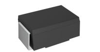


 工商网监
湘ICP备2023018690号
工商网监
湘ICP备2023018690号

