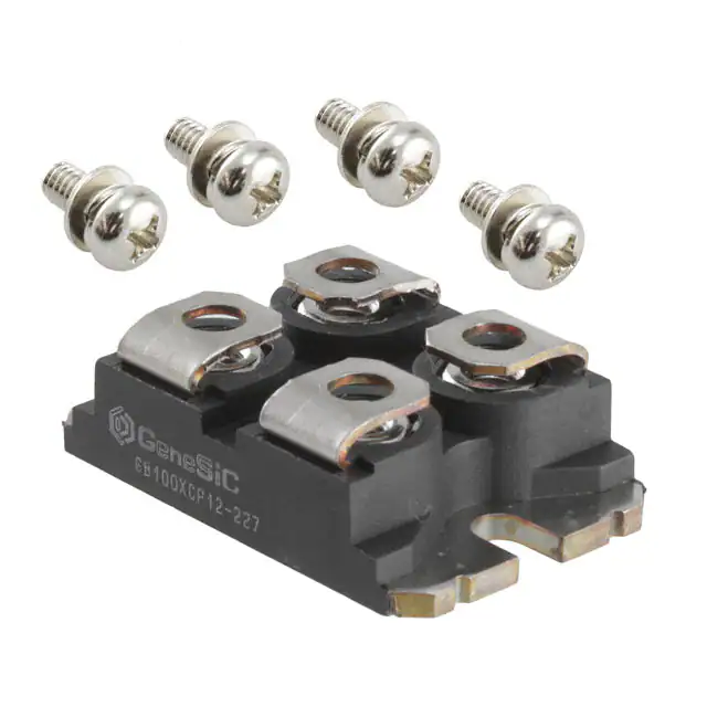
GB100XCP12-227
IGBT/SiC Diode Co-pack
VCES
=
ICM
=
VCE(SAT) =
Features
1200 V
100 A
1.9 V
Package
Optimal Punch Through (OPT) technology
SiC freewheeling diode
Positive temperature coefficient for easy paralleling
Extremely fast switching speeds
Temperature independent switching behavior of SiC rectifier
Best RBSOA/SCSOA capability in the industry
High junction temperature
Industry standard packaging
RoHS Compliant
2
3
3
2
1
1
3
SOT 227
Advantages
Applications
Industry's highest switching speeds
High temperature operation
Improved circuit efficiency
Low switching losses
Solar Inverters
Aerospace Actuators
Server Power Supplies
Resonant Inverters > 100 kHz
Inductive Heating
Electronic Welders
Maximum Ratings at Tj = 175 °C, unless otherwise specified
Parameter
Symbol
Conditions
Values
Unit
VCES
IC
ICM
VGES
TC 130 °C
Limited by Tvjmax
1200
100
200
± 20
V
A
A
V
IGBT Short Circuit SOA
tpsc
VCC = 900 V, V CEM 1200 V
VGE 15 V, Tvj 125 ºC
10
s
Operating Temperature
Storage Temperature
Isolation Voltage
Tvj
Tstg
VISOL
ISOL < 1 mA, 50/60 Hz, t = 1 s
IF
IFM
TC 130 ºC
TC = 25 ºC, tP = 10 s
IF,SM
RthJC
RthJC
IGBT
Collector-Emitter Voltage
DC-Collector Current
Peak Collector Current
Gate Emitter Peak Voltage
-40 to +175
-40 to +175
3000
°C
°C
V
tP = 10 ms, half sine, TC = 25 ºC
100
tbd
tbd
A
A
A
IGBT
SiC Diode
0.08
0.53
°C/W
°C/W
Free-wheeling Silicon Carbide diode
DC-Forward Current
Non Repetitive Peak Forward Current
Surge Non Repetitive Forward Current
Thermal Characteristics
Thermal resistance, junction - case
Thermal resistance, junction - case
Mechanical Properties
Mounting Torque
Terminal Connection Torque
Weight
Case Color
Dimensions
Feb 2012
min.
Md
Values
typ.
1.5
1.3
1.5
29
Black
38 x 25.4 x 12
http://www.genesicsemi.com/index.php/sic-products/copack
max.
Nm
Nm
g
mm
Pg1 of 6
�GB100XCP12-227
Electrical Characteristics at Tj = 175 °C, unless otherwise specified
Parameter
Symbol
Conditions
VGE(th)
ICES,25
ICES,175
IGES
VCE(TO)
RCE,25
RCE,175
VGE = VCE, IC = 4 mA, Tj = 25 ºC
VGE = 0 V, VCE = VCES, Tj = 25 ºC
VGE = 0 V, VCE = VCES, Tj = 175 ºC
VCE = 0 V, VGE = 20 V, Tj = 175 ºC
Tj= 25ºC
VGE = 15 V, Tj = 25 ºC
VGE = 15 V, Tj = 175 ºC
IC = 100 A, VGE = 15 V,
Tj = 25 ºC (175 ºC)
min.
Values
typ.
max.
Unit
IGBT
Gate Threshold Voltage
Collector-Emitter Leakage Current
Gate-Leakage Current
Collector-Emitter Threshold Voltage
Collector-Emitter Slope Resistance
Collector-Emitter Saturation Voltage
VCE(SAT)
Input Capacitance
Output Capacitance
Reverse Transfer Capacitance
Internal Gate Resistance
Cies
Coes
Cres
RGint
Gate Charge
QG
Module Lead Resistance
Rmod
Reverse Bias Safe Operating Area
RBSOA
Short Circuit Current
Short Circuit Duration
Rise Time
Fall Time
Turn On Delay Time
Turn Off Delay Time
Turn-On Energy Loss Per Pulse
Turn-Off Energy Loss Per Pulse
Rise Time
Fall Time
Turn On Delay Time
Turn Off Delay Time
Turn-On Energy Loss Per Pulse
Turn-Off Energy Loss Per Pulse
Isc
tsc
tr
tf
td(on)
td(off)
Eon
Eoff
tr
tf
td(on)
td(off)
Eon
Eoff
5
6.2
0.10
3.15
-400
VGE = 0 V, VCE = 25 V,
f = 1 MHz, Tj = 150 ºC
VCC= 750 V, IC = 100 A,
VGE= -8..15 V, Tj= 25 ºC (125 °C)
Tc= 25 ºC (175 ºC)
Tj=175 ºC, Rg=56 , VCC=1200 V,
VGE=15 V
Tj = 175 ºC, Rg = 56 , VCC = 900 V,
VGE = ±15 V
VCC= 800 V, IC = 100 A,
Rgon = Rgoff = 10 ,
VGE(on)= 15 V, VGE(off)= -8 V,
LS = 0.8 µH, Tj= 25 ºC
VCC= 800 V, IC = 100 A,
Rgon = Rgoff = 10 ,
VGE(on)= 15 V, VGE(off)= -8 V,
LS = 0.8 µH, Tj= 175 ºC
7
1
400
1.1
7.9
11.4
V
mA
mA
nA
V
m
m
1.9 (2.2)
V
8.55
1.39
0.25
2
nF
nF
nF
900 (900)
nC
tbd
m
150
A
470
10
254
153
244
488
14.2
15.7
211
172
240
636
11.1
21.8
A
s
ns
ns
ns
ns
mJ
mJ
ns
ns
ns
ns
mJ
mJ
Free-wheeling Silicon Carbide Diode
Forward Voltage
Threshold Voltage at Diode
Peak Reverse Recovery Current
Reverse Recovery Time
Rise Time
Fall Time
Turn-On Energy Loss Per Pulse
Turn-Off Energy Loss Per Pulse
Reverse Recovery Charge
Rise Time
Fall Time
Turn-On Energy Loss Per Pulse
Turn-Off Energy Loss Per Pulse
Reverse Recovery Charge
Feb 2012
VF
VD(TO)
Irrm
trr
tr
tf
Eon
Eoff
Qrr
tr
tf
Eon
Eoff
Qrr
IF = 100 A, VGE = 0 V,
Tj = 25 ºC (175 ºC )
Tj = 25 ºC
IF = 100 A, VGE = 0 V, VR = 800 V,
-dI F/dt = 625 A/µs, Tj = 175 ºC
VCC= 800 V, IC = 100 A,
Rgon = Rgoff = 10 ,
VGE(on)= 15 V, VGE(off)= -8 V,
LS = 0.8 µH, Tj= 25 ºC
VCC= 800 V, IC = 100 A,
Rgon = Rgoff = 10 ,
VGE(on)= 15 V, VGE(off)= -8 V,
LS = 0.8 µH, Tj= 175 ºC
http://www.genesicsemi.com/index.php/sic-products/copack
2.08 (3.5)
V
0.8
10
100
148
336
218
113
730
178
268
23
334
480
V
A
ns
ns
ns
J
J
nC
ns
ns
J
J
nC
Pg2 of 6
�GB100XCP12-227
Figure 1: Typical Output Characteristics at 25 °C
Figure 2: Typical Output Characteristics at 175 °C
Figure 3: Typical Transfer Characteristics
Figure 4: Typical Blocking Characteristics
Figure 5: Typical FWD Forward Characteristics
Figure 6: Typical Turn On Gate Charge
Feb 2012
http://www.genesicsemi.com/index.php/sic-products/copack
Pg3 of 6
�GB100XCP12-227
Figure 7: Typical Hard-Switched IGBT Turn On
Waveforms
Figure 8: Typical Hard-Switched IGBT Turn Off
Waveforms
Figure 9: Typical Hard-Switched Free-wheeling SiC Diode
Turn Off Waveforms
Figure 10: Typical Hard-Switched Free-wheeling SiC Diode
Turn On Waveforms
Figure 11: Typical Module Energy Losses and Switching
Times at IGBT Turn On vs. Temperature
Figure 12: Typical Module Energy Losses and Switching
Times at IGBT Turn Off vs. Temperature
Feb 2012
http://www.genesicsemi.com/index.php/sic-products/copack
Pg4 of 6
�GB100XCP12-227
Figure 13: Typical Module Energy Losses and Switching
Times at IGBT Turn On vs. Current
Figure 14: Typical Module Energy Losses and Switching
Times at IGBT Turn Off vs. Current
Figure 15: Typical Hard-Switched Reverse Recovery
Charge vs. Temperature
Figure 16: Typical C-V Characteristics
Feb 2012
http://www.genesicsemi.com/index.php/sic-products/copack
Pg5 of 6
�GB100XCP12-227
Package Dimensions:
SOT-227
PACKAGE OUTLINE
NOTE
1. CONTROLLED DIMENSION IS INCH. DIMENSION IN BRACKET IS MILLIMETER.
2. DIMENSIONS DO NOT INCLUDE END FLASH, MOLD FLASH, MATERIAL PROTRUSIONS
Revision History
Date
Revision
Comments
Supersedes
2013/02/08
2012/07/30
2011/01/06
2
1
0
Updated Electrical Characteristics
Second generation release
Initial release
GA100XCP12-227
Published by
GeneSiC Semiconductor, Inc.
43670 Trade Center Place Suite 155
Dulles, VA 20166
GeneSiC Semiconductor, Inc. reserves right to make changes to the product specifications and data in this document without notice.
GeneSiC disclaims all and any warranty and liability arising out of use or application of any product. No license, express or implied to any
intellectual property rights is granted by this document.
Unless otherwise expressly indicated, GeneSiC products are not designed, tested or authorized for use in life-saving, medical, aircraft
navigation, communication, air traffic control and weapons systems, nor in applications where their failure may result in death, personal
injury and/or property damage.
Feb 2012
http://www.genesicsemi.com/index.php/sic-products/copack
Pg6 of 6
�


 工商网监
湘ICP备2023018690号
工商网监
湘ICP备2023018690号
